Table of Contents
Advertisement
Quick Links
INSTRUCTIONS AND ILLUSTRATED PARTS MANUAL
INSTRUCCIONES Y CATALOGO DE PARTES Y PIEZAS
81500B2
81500BA2
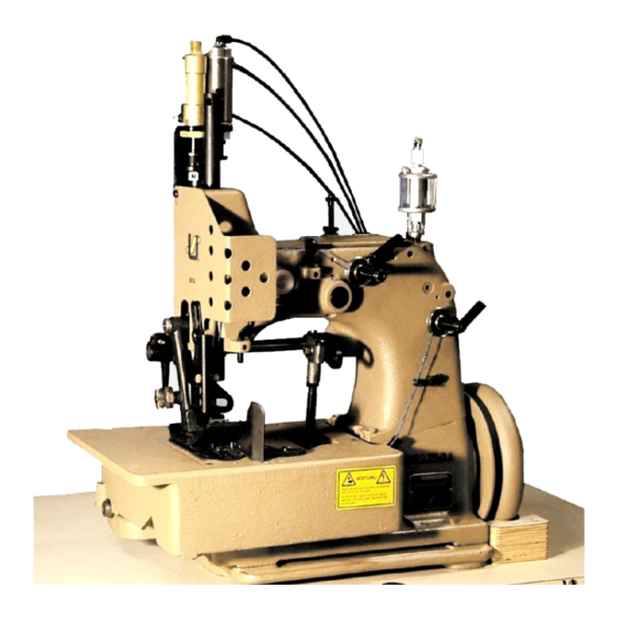
MIRAKLES SINGLE NEEDLE, SINGLE, TWO OR THREE
THREAD OVERSEAMING MACHINES
MIRAKLES, MAQUINA OVERLOCK, DE UNA AGUJA, UNO,
DOS O TRES HILOS
MANUAL NO. / CATALOGO NR. G234
FOR STYLES / PARA ESTILOS
81500A, B, B1H, B2, BA, BA1H, BA2, C, E
Advertisement
Table of Contents

Related Manuals for UnionSpecial 81500B2


Summary of Contents for UnionSpecial 81500B2
- Page 1 INSTRUCTIONS AND ILLUSTRATED PARTS MANUAL INSTRUCCIONES Y CATALOGO DE PARTES Y PIEZAS 81500B2 81500BA2 MIRAKLES SINGLE NEEDLE, SINGLE, TWO OR THREE THREAD OVERSEAMING MACHINES MIRAKLES, MAQUINA OVERLOCK, DE UNA AGUJA, UNO, DOS O TRES HILOS MANUAL NO. / CATALOGO NR. G234...
- Page 2 MANUAL NO. G234 CATALOGO Nº G234 INSTRUCTIONS AND ILLUSTRATED PARTS LIST INSTRUCCIONES Y LISTA DE PARTES FOR 81500 SERIES MACHINES ILUSTRADAS MODELOS SERIE 81500 Fitfth Edition Copyright 2002 Quinta Edición © 2002 Union Special GmbH Union Special GmbH Rights Reserved in All Derechos Reservados Countries en todos los paises del mundo...
-
Page 3: Table Of Contents
TABLE OF CONTENTS INDICE PAGE / PAGINA SAFETY RULES 4 - 5 REGLAS DE SEGURIDAD IDENTIFICATION OF MACHINES IDENTIFICACION DE LAS MAQUINAS APPLICATION OF THIS INSTRUCTION MANUAL APLICACION DE ESTE MANUAL DE INSTRUCCIONES 6 - 7 STYLES OF MACHINES ESTILOS DE MAQUINAS 8 –... -
Page 4: Reglas De Seguridad
SAFETY RULES REGLAS DE SEGURIDAD Before putting the machines described in this manual Antes de poner en marcha las máquinas descritas en into service, carefully read the instructions. The starting este manual, hay que leer cuidadosamente las ins- of each machine is only permitted after taking notice of trucciones. -
Page 5: Identification Of Machines
Maintenance, repair and conversion work (see item 8) Mantenimiento, reparaciones y trabajos de conversión (véase No. 8) solamente pueden ser efectuados por must be done only by trained technicians or s p e c i a l técnicos entrenados o personal especializado bajo skilled personnel under condsideration of the instructions. -
Page 6: Styles Of Machines
STYLES OF MACHINES ESTILOS DE MAQUINAS: „MIRAKLES“ single needle, single two and three thread „MIRAKLES“ máquina overlock de una aguja, uno, dos o tres overseamers with 71 mm (2 51/64 in.) needle throw. Ma- hilos, con un recorrido de la barra de aguja de 71 mm. Lubrica- nual lubrication. - Page 7 Guides for filler cord from the top and / or from below desde arriba y/o desde abajo de la aguja izquierda. for sealing the needle punctures of the left needle. 81500B2: Igual a la 81500B1H, pero sin ningún cortador de cadeneta. 81500B2: Same as 81300B1H, but without any thread chain cutter.
-
Page 8: Installation Instalacion
INSTALLATION INSTALACION... - Page 9 INSTALACION (Continuación) INSTALLATION (continued) Desempaque la máquina y los accesorios. Unpack the sewing machine and the accessories. Monte la placa de base (A, Fig. 1) con los 4 tornillos, Mount the base plate (A, Fig. 1) with four screws, nuts tuercas y arandelas (B) en los huecos previstos en la and washers (B) in the provided holes on the table board.
-
Page 11: Installation
INSTALACION (Continuación) INSTALLATION (continued) 11. Hook the lifter chain to the lifter lever of the sewing 11. Enganche la cadena a la palanca levantadora de la machine and to the small treadle on the sewing table. máquina de coser y al pequeño pedal en la mesa de la máquina de coser. - Page 12 LUBRICATING LUBRICACION Turn off main power switch before Antes de lubricar, apague el interruptor lubricating! When using clutch motors with principal. Con un motor de embrague or without actuation lock wait until motor sin freno espere hasta que el motor se has completely stopped.
-
Page 13: Lubricating
LUBRICACION (Continuación) LUBRICATING (continued) INSTRUCCIONES DE OPERACION PREPARING FOR OPERATING Antes de poner en marcha una nueva máquina por la primera Before operating a new machine for the first time, the sight vez, hay que fijar y ajustar el engrasador cuentagotas. Lubrique feed oiler has to be adjusted. -
Page 14: Threading Diagram
THREADING DIAGRAM DIAGRAMA DE ENHEBRADO CAUTION! Turn off main power switch before PRECAUCION! Apague el motor principal antes de threading! When using clutch motors with enhebrar!. Cuando utilice motor con clu- or without actuation lock wait until the tch debe esperar hasta que el mismo se motor has completely stopped! detenga totalmente!. -
Page 15: Threading Diagram
THREADING DIAGRAM DIAGRAMA DE ENHEBRADO CAUTION! Turn off main power switch before PRECAUCION! Apague el motor principal antes de threading! When using clutch motors with enhebrar!. Cuando utilice motor con clu- or without actuation lock wait until the tch debe esperar hasta que el mismo se motor has completely stopped! detenga totalmente!. -
Page 16: Operating Instructions
OPERATING INSTRUCTIONS INSTRUCCIONES DE OPERACION THREADING DIAGRAMA DE ENHEBRADO CAUTION! Turn off main power switch before PRECAUCION! Apague el motor principal antes de threading! When using clutch motors enhebrar!. Cuando utilice motor con clu- with or without actuation lock wait until tch debe esperar hasta que el mismo se the motor has stopped! detenga totalmente!. - Page 17 ALIMENTACION DEL HILO DE LA AGUJA NEEDLE THREAD TAKE-UP Generalmente el rodillo del alimentador del hilo de la aguja Basically the needle thread take-up roller (B, Figs. 5 and (B, Figs. 5 y 5A), que está situado en la parte delantera 5A), located left on the upper bed casting under the face izquierda del brazo debajo de la tapa frontal, debería estar cover, is set as low as possible.
- Page 18 Ajuste la guía tope (A, Figs. 6 y 6A) tan cerca como sea Set the edge guide (A, Figs. 6 and 6 A) laterally as close posible al pie prensatelas, pero sin tocarlo. Cuando suelte los as possible to the presser foot, without contacting it. When dos tornillos (B) la guía tope (A) podrá...
-
Page 19: Maintenance
MANTENIMIENTO MAINTENANCE PRECAUCION! Antes de efectuar cualquier trabajo de CAUTION! Turn off main power switch before doing mantenimiento, apague el interruptor maintenance works! When using clutch principal de la máquina. Con un motor motors with or without actuation lock wait de embrague sin freno, espere hasta que until the motor has stopped! el motor se detenga completamente! -
Page 20: Instruction For Mechanics
INSTRUCTIONS FOR MECHANICS INSTRUCCIONES PARA MECANICOS Preste atención a las REGLAS DE SEGURI- Observe the SAFETY RULES when ma- DAD mientras realiza ajustes! king adjustments! Antes de realizar ajustes en la máquina, quite la tapa frontal y Before adjusting the machine remove the face cover and el protector de dedos, el diente alimentador superior, el pie the finger guard left on the machine head, the upper feed prensatelas, la plancha de tela con la plancha articulada y la... - Page 22 AJUSTE DE LA ALTURA DE LA BARRA DE AGUJA SETTING THE HEIGHT OF THE NEEDLE BAR Gire el volante en dirección de operación hasta que la pun- Rotate handwheel in operating direction until the point of ta del looper inferior (A, Fig. 9) o la punta del spreader infe- lower looper (A, Fig.
- Page 23 Fig. 10 Fig. 11 Fig. 11 A Fig. 11 B Fig. 11 C Fig. 12...
- Page 24 Rotate handwheel in operating direction until the upper Gire el volante en dirección de operación hasta que el spreader superior esté en su posición extrema inferior. El spreader is in its extreme right lower end position. The upper spreader superior no debe tocar ninguna parte de la máqui- spreader should not contact any machine parts during its na durante esta operación.
- Page 26 In the extreme left upper end position of upper looper (A, En la posición izquierda superior extrema del looper supe- Fig. 11 B), the distance between the left edge of looper eye rior (A, Fig. 11 B), la distancia entre el costado izquierdo del and the center of needle (N) should be 6 mm (15/64 in.) ojo del looper y el centro de la aguja (N) debería ser de 6 If an adjustment is necessary, loosen nuts (L and R, Fig.
- Page 27 SETTING THE LOWER FEED DOG AJUSTE DEL DIENTE ALIMENTADOR INFERIOR The lower feed dog (A, Fig. 15) should center laterally in the El diente alimentador inferior (A, Fig. 15) debe estar centrado slots of throat plate (B). If an adjustment is necessary loosen lateralmente en las ranuras de la plancha de aguja (B).
- Page 29 Para ajustar el diente alimentador superior con respecto a los For setting the upper feed dog with respect to the slot ends extremos de las ranuras en el pie prensatelas y los espacios in the presser foot and the tooth spaces of the lower feed entre los dientes del diente alimentador inferior, hay que sol- dog, loosen screw (D, Fig.
- Page 30 The presser foot lift is limited with the upper stop collar (D, La elevación del pie prensatelas se limita con el anillo de ajuste (D, Fig. 23) en la parte superior de la barra derecha Fig. 23) on the right presser bar. When the needle is in its del pie prensa tela.
- Page 31 AJUSTE DE LOS RELES DE TIEMPO EN LA CAJA DE SETTING THE TIME RELAYS IN THE SWITCH BOX CONTROL DEL CORTADOR CALIENTE DE CADENE- OF HOT THREAD CHAIN CUTTER Styles 81500B1H, BA1H Estilos 81500B1H, BA1H The switch box includes two time relays marked K2T La caja de control incluye dos relés de tiempo marcados and K4T.
-
Page 32: Ordering Wear And Spare Parts
PEDIDO DE PIEZAS DE REPUESTOS ORDERING WEAR AND SPARE PARTS Este catálogo fue diseñado para facilitar los pedidos de los The following section of this manual simplifies ordering repuestos. Los dibujos de grupos específicos del mecanismo wear and spare parts. Exploded views of various sections demuestran la posición de las piezas en la máquina de coser. -
Page 33: Views And Description Of Parts
VIEWS AND DESCRIPTION OF PARTS VISTAS Y DESCRIPCIONES DE LAS PARTES Y PIEZAS... -
Page 35: Bocinas Y Partes De Lubricacion
BUSHING, SIGHT FEED OILER, OILERS BOCINAS Y PARTES DE LUBRICACION Amt. Req. Ref. No. Part No. Description Descripción Cant.Req. Parte No. Ref. No. 80862 Presser Bar Bushing Bocina de la barra del pie prensatelas 81373A Needle Bar Bushing Bocina de la barra de aguja 80293A Oil Distributor Distribuidor de aceite... -
Page 37: Cloth Plate, Base Plate, Guards And Miscellaneous Covers Tapa Y Base De La Maquina, Guardas Y Otras Tapas
CLOTH PLATE, BASE PLATE, GUARDS AND MISCELLANEOUS COVERS TAPA Y BASE DE LA MAQUINA, GUARDAS Y OTRAS TAPAS Ref. No. Part No. Amt. Req. Description Descripción Ref. No. Parte No. Cant.Req. 80673CB Needle Bar Guard Protector de la barra de aguja 80888 Arm Cover Cubierta del brazo... -
Page 39: Thread Tensions And Thread Guide Parts Tensiones De Los Hilos Y Partes Del Guia Hilos
THREAD TENSIONS AND THREAD GUIDE PARTS TENSIONES DE LOS HILOS Y PARTES DEL GUIA HILOS Amt. Req. Part No. Ref. No. Description Descripción Cant.Req. Parte No. Ref. No. HS106 Tension Post for 81500A, B, BA Poste de la tensión para 81500A, B, BA 81500C 81500C 81500E... -
Page 41: Tensiones De Los Hilos Y Partes Del Guia Hilos
THREAD TENSIONS AND THREAD GUIDE PARTS TENSIONES DE LOS HILOS Y PARTES DEL GUIA HILOS Amt. Req. Ref. No. Part No. Description Descripción Cant.Req. Parte No. Ref. No. Ref. Nos. 1 - 32 see page 39 Refs. Nos. 1 - 32, ver página 39 81256A Thread Sleeve for looper thread Manguito para el hilo del looper... -
Page 43: Needle Bar, Needle Lever, Crankshaft, Handwheel
NEEDLE BAR, NEEDLE LEVER, CRANK SHAFT, HANDWHEEL BARRAS DE AGUJA, LEVANTADOR AGUJA, EJE PRINCIPAL, VOLANTE Description Ref. No. Part No. Amt. Req. Descripción Ref. No. Parte No. Cant.Req. 81317 Needle Bar Barra de la aguja Sleeve Manguito 80620H Collar for 81500A Anillo de metal para 81500A 81566 22536... -
Page 45: Looper Drive Mechanism Mecanismo De Operacion Del Looper
LOOPER DRIVE MECHANISM MECANISMO DE OPERACION DEL LOOPER Amt. Req. Ref. No. Part No. Description Descripción Cant.Req. Parte No. Ref. No. G29442L Upper Spreader / Looper Drive Conj. Excéntrica de accionamiento del looper y Eccentric Assembly spreader superior G29442LA Lower Looper Drive Eccentric Assy. Conj. -
Page 47: Upper And Lower Feed Drive Mechanism Mecanismos Del Transporte Superior E Inferior
UPPER AND LOWER FEED DRIVE MECHANISM MECANISMOS DEL TRANSPORTE SUPERIOR E INFERIOR Amt. Req. Ref. No. Part No. Description Descripción Cant.Req. Parte No. Ref. No. 80740 Drive Shaf t Eje impulsor 80791 Drive Lever Palanca del impulsor BP108 Hex. Head Cap Screw Tornillo con cabeza hexagonal 51147 Collar... -
Page 49: Presser Bars, Presser Bar Springs And Presser Foot Lifter Lever
PRESSER BARS, PRESSER BAR SPRINGS AND PRESSER FOOT LIFTER LEVER BARRAS Y MUELLES DEL PIE PRENSATELAS Y LEVANTADOR DEL PIE PRENSATELAS Amt. Req. Ref. No. Part No. Description Descripción Cant.Req. Ref. No. Parte No. 80648 Lifter Lever Palanca levantadora Shoulder Screw for lifter lever Tornillo insertable para palanca levantadora 80649 Spring... -
Page 51: Prensatela
A10455-813E Piezas del sistema electroneumático para feed pressure and lifter for presión y levantamiento del transporte supe- 81500B2, BA2 rior y pie prensatelas para 81500B2, BA2 Electro-Pneumatic Parts Kit for upper 1-22, A10455H813E Piezas del sistema electroneumático para feed pressure, lifter and hot thread 24-35 presión y levantamiento del transporte supe-... -
Page 53: Control For Electro-Pneumatic Hot Thread Chain Cutter For 81500B1H, Ba1H Control Para El Sistema Electro Neumatico Cortador Caliente De Cadeneta Para 81500B1H, Ba1H
CONTROL FOR ELECTRO-PNEUMATIC HOT THREAD CHAIN CUTTER FOR 81500B1H, BA1H CONTROL PARA EL SISTEMA ELECTRO NEUMATICO CORTADOR CALIENTE DE CADENETA PARA 81500B1H, BA1H Amt. Req. Ref. No. Part No. Description Descripción Cant.Req. Ref. No. Parte No. Control para cortador caliente de cadeneta 99712HAE Control for Hot Thread Chain Cutter PA Tube 6 x 4;... -
Page 55: Control Para El Sistema Electro Neumatico Cortador Caliente De Cadeneta Para 81500B1H, Ba1H
CONTROL FOR ELECTRO-PNEUMATIC HOT THREAD CHAIN CUTTER 81500B1H, BA1H CONTROL PARA EL SISTEMA ELECTRO NEUMATICO CORTADOR CALIENTE DE CADENETA PARA 81500B1H, BA1H Amt. Req. Ref. No. Part No. Description Descripción Cant.Req. Ref. No. Parte No. Control Box of hot thread chain cutter Caja de control para cortador caliente de 999-315B cadeneta 999-315B... -
Page 57: Electro-Pneumatic Hot Thread Chain Cutter For 81500B1H, Ba1H Sistema Electro Neumatico Cortador Caliente De Cadeneta Para 81500B1H, Ba1H
ELECTRO-PNEUMATIC HOT THREAD CHAIN CUTTER FOR 81500B1H, BA1H SISTEMA ELECTRONEUMATICO CORTADOR CALIENTE DE CADENETA PARA 81500B1H, BA1H Amt. Req. Ref. No. Part No. Description Descripción Cant.Req. Ref. No. Parte No. El.-Pneum.Hot Thread Chain Cutter Cortador caliente electroneumático 99712H813 Hot Cutter for thread chain with Cortador caliente de cadeneta con caja 999-315B control box... -
Page 59: Sewing Parts; Styles 81500A, B, B1H, B2, Ba, Ba1H, Ba2 And 81500C Piezas De Formacion De Costura, Modelos 81500A, B, B1H, B2, Ba, Bah1, Ba2 Y 81500C
SEWING PARTS, STYLES 81500A, B, B1H, B2, BA , BA1H, BA2 AND 81500C PIEZAS DE FORMACION DE COSTURA, ESTILOS 81500A, B, B1H, B2, BA, BA1H, BA2 Y 81500C Amt. Req. Ref. No. Part No. Description Descripción Cant. Req. Ref. No. Parte No. -
Page 61: Sewing Parts, Style 81500E
SEWING PARTS, STYLE 81500E PIEZAS DE FORMACION DE COSTURA, ESTILO 81500E Amt. Req. Ref. No. Part No. Description Descripción Cant.Req. Ref. No. Parte No. Diente alimentador, superior 81326 Feed Dog, upper Tornillo 136A Screw Pie prensatelas 81530E Presser Foot Tornillo 22596B Screw Lengüeta del prensatelas, marcada "WL-19"... -
Page 63: Accessories Accesorios
ACCESSORIES ACCESORIOS Amt. Req. Ref. No. Part No. Description Descripción Cant.Req. Ref. No. Parte No. Thread Stand, 1 Cone for 81500E Porta conos, 1 hilo para 81500E 93065B1 Thread Stand, 2 Cones Porta conos, 2 hilos 93065B2 Thread Stand, 3 Cones Porta conos, 3 hilos 93065B3 Base... - Page 65 ACCESSORIES ACCESORIOS Ref. No. Part No. Descripción Amt. Req. Description Ref. No. Parte No. Cant.Req. 93065D2 Thread Stand, 2 Cones Porta conos, 2 hilos Thread Stand, 3 Cones Porta conos, 3 hilos 93065D3 Thread Stand, 4 Cones 93065D4 Porta conos, 4 hilos 93065D5 Thread Stand, 5 Cones Porta conos, 5 hilos...
-
Page 66: Numerical Index Of Parts Indice Numerico De Partes
NUMERICAL INDEX OF PARTS INDICE NUMERICO DE PARTES Part No. Page Part No. Page Part No. Page Part No. Page Parte No. Pág. Parte No. Pág. Parte No. Pág. Parte No. Pág. 1021U ... 65 22894H ... 43 80630C ... 43, 47 80888 ... - Page 67 NUMERICAL INDEX OF PARTS INDICE NUMERICO DE PARTES Part No. Page Part No. Page Part No. Page Part No. Page Parte No. Pág. Parte No. Pág. Parte No. Pág. Parte No. Pág. G29099Q ... 47 81511 ... 59 93A ... 39, 47 99712H813 ...
Need help?
Do you have a question about the 81500B2 and is the answer not in the manual?
Questions and answers