
Subscribe to Our Youtube Channel
Related Manuals for UnionSpecial G230A-GR


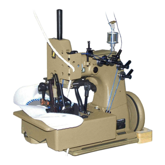
Summary of Contents for UnionSpecial G230A-GR
- Page 1 INSTRUCTIONS AND ILLUSTRATED PARTS MANUAL BETRIEBSANLEITUNG UND ILLUSTRIERTES TEILEVERZEICHNIS MANUAL NO. / KATALOG NR. G230A-GR FOR STYLES / FÜR TYPEN 81300A, AJ, A1H, A2 81300B, B1H, B2 03/01/10...
- Page 2 MANUAL NO. G230A-GR KATALOG NR. G230A-GR INSTRUCTIONS AND ILLUSTRATED PARTS LIST FOR BETRIEBSANLEITUNG UND ILLUSTRIERTES 81300 SERIES MACHINES TEILEVERZEICHNIS FÜR MASCHINENKLASSE 81300 First Edition Copyright 2007 Erste Auflage © 2007 Weltweit beanspruchte Union Special GmbH Union Special GmbH Rights Reserved in All...
-
Page 3: Table Of Contents
Page TABLE OF CONTENTS Seite INHALTSVERZEICHNIS SAFETY RULES 4 - 5 SICHERHEITSHINWEISE IDENTIFICATION OF MACHINES BEZEICHNUNG DER MASCHINEN APPLICATION OF THIS INSTRUCTION MANUAL BENÜTZUNG DIESER BETRIEBSANLEITUNG ORDERING WEAR AND SPARE PARTS BESTELLEN VON VERSCHLEISS- UND ERSATZTEILEN STYLES OF MACHINES MASCHINENTYPEN INSTALLATION 8 - 9 AUFSTELLUNG... -
Page 4: Safety Rules
SAFETY RULES SICHERHEITSHINWEISE Before putting the machines described in this manual Lesen Sie vor Inbetriebnahme der in diesem Katalog into service, carefully read the instructions. beschriebenen Maschinen die Betriebsanleitung starting of each machine is only permitted after sorgfältig. Jede Maschine darf erst nach Kenntnis- taking notice of the instructions and by qualified nahme der Betriebsanleitung und nur durch operators. - Page 5 Maintenance, repair and conversion work (see Wartungs-, Reparatur- und Umbauarbeiten (siehe item 8) must be done only by trained technicians Punkt 8) dürfen nur von Fachkräften oder ent- or special skilled personnel under condsideration sprechend unterwiesenen Personen unter Beach- of the instructions. tung der Betriebsanleitung durchgeführt werden.
-
Page 6: Identification Of Machines
IDENTIFICATION OF MACHINES BEZEICHNUNG DER MASCHINEN Each UNION SPECIAL 81300 series machine is Jede UNION SPECIAL 81300 Maschine hat eine in das identified by a style number, which is stamped on Typenschild eingeprägte Typennummer, das rechts the style plate affixed to the right front of machine. vorne am Gehäuse befestigt ist. -
Page 7: Styles Of Machines
STYLES OF MACHINES MASCHINENTYPEN 81300A: Combined ANTAEUS / HERAKLES two needle 81300A: Kombinierte ANTAEUS / HERAKLES Zweinadel-Vier- four thread safety stitch machine. Lower and upper faden-Sicherheitsnahtmaschine. Unter- und Obertransport. feed. Adjusted for polypropylene sewing threads. Justiert für Polypropylen-Nähfäden Manual lubrication. Manuelle Schmierung. -
Page 8: Installation Aufstellung
INSTALLATION AUFSTELLUNG... - Page 9 INSTALLATION (continued) AUFSTELLUNG (Fortsetzung) Unpack the sewing machine and the accessories. Packen Sie die Nähmaschine und das Zubehör aus. Mount the base plate (A) with four screws, nuts and Montieren Sie die Grundplatte (A) mit vier Schrauben, washers (B) in the provided holes on the table board. Muttern und Scheiben (B) in den dafür vorgesehenen Bohrungen auf der Nähtischplatte.
-
Page 10: Lubricating
LUBRICATING ÖLEN Turn off main power switch before lubricating! CAUTION! Schalten Sie vor dem Ölen den Haupt- ACHTUNG! When using clutch motors with or without schalter aus! Beim Gebrauch von Kupp- actuation lock wait until motor has com- lungsmotoren mit oder ohne Betätigungs- pletely stopped. -
Page 11: Needles
LUBRICATING (continued) ÖLEN (Fortsetzung) PREPARING FOR OPERATION VORBEREITEN ZUR INBETRIEBNAHME Before operating a new machine for the first time, the Bevor eine neue Maschine zum ersten Mal in Betrieb sight feed oiler has to be adjusted. All lubricating genommen wird, muß der Tropföler eingestellt werden. points, indicated on the oiling diagram (Fig. -
Page 12: Threading Diagram
THREADING DIAGRAM EINFÄDELANLEITUNG CAUTION! Turn off main power switch before ACHTUNG! Schalten Sie vor dem Einfädeln den Haupt- threading! When using clutch motors schalter aus! Warten Sie bei Kupplungsmo- with or without actuation lock wait until toren mit oder ohne Betätigungssperre den the motor has completely stopped! Stillstand des Motors ab! Fig. -
Page 13: Operating Instructions
OPERATING INSTRUCTIONS BEDIENUNGSANLEITUNG THREADING EINFÄDELN 81300 series are threaded as shown in Fig. 2. Die Maschinen 81300 werden, wie in Fig. 2 gezeigt, ein- gefädelt. For threading the needle turn handwheel in operating Drehen Sie zum Einfädeln der Nadel das Handrad in direction until the needle is in the upmost position. -
Page 14: Instructions For Mechanics
INDSTRUCTIONS FOR MECHANICS MECHANIKERANLEITUNG HINT: The right needle forms along with the left lower HINWEIS: Die rechte Nadel bildet zusammen mit dem Untergreifer links hinten, dem rechten oberen Blindgreifer looper at the rear, the right upper spreader with thread hook and the thread retainer the overedge stitch type mit Fadenhaken und dem Fadenholer den Überwend- 502 (HERAKLES). - Page 15 SETTING THE RIGHT UPPER SPREADER FOR THE OVEREDGE EINSTELLUNG DES RECHTEN OBEREN BLINDGREIFERS FÜR STITCH DEN ÜBERWENDLICHSTICH Before inserting a new spreader (F, Fig. 6) remove Bevor Sie einen neuen Blindgreifer (F, Fig. 6) einsetzen, thread hook (J). This facilitates the visual check of the entfernen Sie den Fadenhaken (J).
- Page 16 SETTING THE RIGHT UPPER SPREADER FOR THE OVEREDGE EINSTELLUNG DES RECHTEN OBEREN BLINDGREIFERS FÜR STITCH (continued) DEN ÜBERWENDLICHSTICH (Fortsetzung) Rotate handwheel in operating direction. On the up- Drehen Sie dasHandrad in Nährichtung. Bei der Bewegung ward travel of spreader (F, Fig. 9) the tip of its lower des Blindgreifers (F, Fig.
- Page 17 SETTING THE THREAD RETAINER FOR THE OVEREDGE STITCH EINSTELLUNG DES FADENHOLERS FÜR DEN ÜBERWEND- (continued) LICHSTICH (Fortsetzung) After loosening screw (C, Fig. 11) the thread retainer Nach Lösen der Schraube (C, Fig. 11) kann der Fadenholer (B) can be moved to the left or right. Retighten screw (B) nach links oder rechts verschoben werden.
- Page 18 SETTING THE CROSS LOOPER FOR DOUBLE LOCKED STITCH EINSTELLUNG DES QUERGREIFERS FÜR DOPPELKETTENSTICH (continued) (Fortsetzung) After loosening the two screws (E, Fig. 15) the 0.3 mm Nach Lösen der beiden Schrauben (E, Fig. 15) kann der 0,3 (.012") distance to the left needle is adjustable. Re- mm Abstand zur linken Nadel eingestellt werden.
- Page 19 SETTING THE LOWER FEED DOG EINSTELLUNG DES UNTEREN TRANS- PORTEURS The lower feed dog (A, Fig. 17) should center laterally in the slots Der untere Transporteur (A, Fig. 17) of throat plate (B). muß in den Schlitzen der Stichplatte (B) If an adjustment is necessary seitlich vermittelt sein.
- Page 20 SETTING THE UPPER FEED DOG (continued) EINSTELLUNG DES OBEREN TRANSPORTEURS (Fortsetzung) For setting the small gap between the feed dogs Zum Einstellen des Luftspalts zwischen den Transporteuren loosen nut (F, Fig. 22). Turning in screw (G) in- lösen Sie die Mutter (F, Fig. 22). Eindrehen der Schraube creases the gap, turning it out decreases the gap.
- Page 21 PRESSER FOOT PRESSURE (contiued) DRÜCKERFUSSDRUCK (Fortsetzung) By relocating the collars (C, Fig. 25) which serve as a Durch Verstellen der als Blattfederauflage dienenden Stellringe leaf spring rest on the left and right presser bar, the (C, Fig. 25) auf der linken und rechten Drückerfußstange kann pressure can be changed.
- Page 22 NEEDLE THREAD TAKE-UP AND THREAD TENSIONS NADELFADENABZUG UND FADENSPANNUNGEN Basically the needle thread take-up roller (B, Fig. 2), Standardmäßig wird die Nadelfadenabzugs-Rollenfüh- located left on the upper bed casting under the face rung (B, Fig. 2) links am Gehäuseoberteil unter dem cover, is set as low as possible.
-
Page 23: Views And Description Of Parts
VIEWS AND DESCRIPTION OF PARTS DARSTELLUNGEN UND TEILEBESCHREIBUNGEN... -
Page 25: Bushings, Sight Feed Oiler, Spring Valve Oiler
BUSHING, SIGHT FEED OILER, SPRING VALVE OILER BUCHSEN, TROPFÖLER, KUGELÖLER Ref. No. Part No. Description Beschreibung Amt. Req. Pos. Nr. Teil Nr. Anzahl 80862 Presser Bar Bushing Buchse für Drückerfußstange 81373A Needle Bar Bushing Buchse für Nadelstange GR-80293A Oil Distributor Ölverteiler 22894K Spot Screw, headless... -
Page 27: Cloth Plate, Base Plate, Guards And Miscellaneous Covers
CLOTH PLATE, BASE PLATE, GUARDS AND MISCELLANEOUS COVERS STOFFPLATTE, GRUNDPLATTE, SCHUTZTEILE UND VERSCHIEDENE ABDECKUNGEN Ref. No. Part No. Description Beschreibung Amt. Req. Pos. Nr. Teil Nr. Anzahl 80673CB Needle Bar Guard Nadelstangenschutz 80888 Arm Cover Armdeckel 80764 T-Screw Knebelschraube 35733B Knurled Nut Rändelmutter 81387... - Page 28 Loctite 262 (CE66)
-
Page 29: Thread Tensions And Thread Guide Parts Fadenspannungen Und Fadenführungsteile
THREAD TENSIONS AND THREAD GUIDE PARTS FADENSPANNUNGEN UND FADENFÜHRUNGSTEILE Ref. No. Part No. Description Beschreibung Amt. Req. Pos. Nr. Teil Nr. Anzahl HS106 Tension Post Spannungsbolzen 81292A Tension Post Spannungsbolzen 99623A Spacer Distanzbuchse 80669B Tension Post Ferrule Hülse für Spannungsbolzen 80676A Tension Disc Spannungsscheibe... - Page 30 Loctite 262 (CE66) Loctite 262 (CE66)
-
Page 31: Needle Bar, Needle Lever, Crank Shaft, Handwheel
NEEDLE BAR, NEEDLE LEVER, CRANK SHAFT, HANDWHEEL NADELSTANGE, NADELHEBEL, KURBELWELLE, HANDRAD Ref. No. Part No. Description Beschreibung Amt. Req. Pos. Nr. Teil Nr. Anzahl 81317 Needle Bar Nadelstange 80620H Sleeve Spannhülse 81356B Needle Stop Plate Nadelanschlagplättchen Countersunk Screw Senkschraube 81356A Needle Holder Nadelhalter Set Screw for left needle... -
Page 33: Looper Drive Mechanism Greiferantriebsmechanismus
LOOPER DRIVE MECHANISM GREIFERANTRIEBSMECHANISMUS Ref. No. Part No. Description Beschreibung Amt. Req. Pos. Nr. Teil Nr. Anzahl 81364 Drive Fork for cross looper Antriebsgabel für Quergreifer Screw Schraube 81364A Guide Plate Führungsplättchen Screw Schraube 81370 Oil Felt Ölfilz 81366 Drive Eccentric for cross looper Antriebsexzenter für Quergreifer Spot Screw, headless Gewindestift mit Spitze... - Page 35 LOOPER DRIVE MECHANISM GREIFERANTRIEBSMECHANISMUS Ref. No. Part No. Description Beschreibung Amt. Req. Pos. Nr. Teil Nr. Anzahl 1 - 70 See preceding page Siehe vorhergehende Seite Mutter 35741A Connecting Rod Verbindungsstange Nut, left hand thread Mutter, Linksgewinde 81357 Ball Joint Assembly Kugelgelenk, komplett 81345 Ball Stud...
-
Page 37: Lower And Upper Feed Drive Mechanism Unter- Und Obertransport-Antriebsmechanismus
LOWER AND UPPER FEED DRIVE MECHANISM UNTER- UND OBERTRANSPORT-ANTRIEBSMECHANISMUS Ref. No. Part No. Description Beschreibung Amt. Req. Pos. Nr. Teil Nr. Anzahl 80740 Drive Shaft Antriebswelle 80791 Drive Lever Antriebshebel BP108 Hex. Head Cap Screw Sechskantschraube 51147 Collar Stellring Set Screw Gewindestift 80790 Rocker Lever... -
Page 39: Presser Bars, Leaf Springs And Presser Foot Lifter Lever For 81300A, Aj, A1, B
PRESSER BARS, LEAF SPRINGS AND PRESSER FOOT LIFTER LEVER F0R 81300A, AJ.A1, B DRÜCKERFUSSSTANGEN, BLATTFEDERN UND DRÜCKERFUSSLIFTERHEBEL FÜR 81300A, AJ, A1, B Ref. No. Part No. Description Beschreibung Amt. Req. Pos. Nr. Teil Nr. Anzahl 80648 Lifter Lever Lifterhebel Shoulder Screw for lifter lever Ansatzschraube für Lifterhebel 80649 Spring... -
Page 41: Elektropneumatik-Teilesatz Für Obertransportdruck Und -Liftung Für 81300A1H, A2, B1H, B2
ELECTRO-PNEUMATIC PARTS KIT FOR UPPER FEED PRESSURE AND LIFTER FOR 81300A1H, A2, B1H, B2 WITH ELECTRONIC DRIVE ELEKTROPNEUMATIK-TEILESATZ FÜR OBERTRANSPORTDRUCK UND -LIFTUNG FÜR 81300A1H, A2, B1H, B2 MIT ELEKTRONIK-ANTRIEB Ref. No. Part No. Description Beschreibung Amt. Req. Pos. Nr. Teil Nr. Anzahl 1-33,35 A10455-813E... -
Page 43: Control For Electro-Pneumatic Hot Thread Chain Cutter For 81300A1H, B1H
CONTROL FOR ELECTRO-PNEUMATIC HOT THREAD CHAIN CUTTER FOR 81300A1H, B1H STEUERUNG FÜR ELEKTROPNEUMATISCH BETÄTIGTEN FADENKETTEN-HEISSSCHNEIDER FÜR 81300A1H, B1H Ref. No. Part No. Description Beschreibung Amt. Req. Pos. Nr. Teil Nr. Anzahl 99712HAE Control for Hot Thread Chain Cutter Steuerung für Fadenketten-Heißschneider 134001 PA Tube 6 x 4;... - Page 45 CONTROL FOR ELECTRO-PNEUMATIC HOT THREAD CHAIN CUTTER 81300A1H, B1H STEUERUNG FÜR ELEKTROPNEUMATISCH BETÄTIGTEN FADENKETTEN-HEISSSCHNEIDER 81300A1H, B1H Ref. No. Part No. Description Beschreibung Amt. Req. Pos. Nr. Teil Nr. Anzahl Control Box of hot thread chain Steuergerät des Heißschneiders für cutter 999-315B Fadenkette 999-315B 90242TA Control Board...
-
Page 47: Electro-Pneumatic Hot Thread Chain Cutter For 81300A1H, B1H
ELECTRO-PNEUMATIC HOT THREAD CHAIN CUTTER FOR 81300A1H, B1H ELEKTROPNEUMATISCH BETÄTIGTER FADENKETTEN-HEISSSCHNEIDER FÜR 81300A1H, B1H Ref. No. Part No. Description Beschreibung Amt. Req. Pos. Nr. Teil Nr. Anzahl 99712H813 El.-Pneum.Hot Thread Chain Cutter El.-pneum.Fadenketten-Heißschneider 999-315B Hot Cutter for thread chain with Heißschneider für Fadenketten mit control box Steuergerät... -
Page 49: Sewing Parts Nähteile
SEWING PARTS NÄHTEILE Ref. No. Part No. Description Beschreibung Amt. Req. Pos. Nr. Teil Nr. Anzahl Transporteur, oben 81326 Feed Dog, upper 136A Screw Schraube 81320C Presser Foot Assembly Drückerfuß, komplett 81330C Presser Foot Bottom Drückerfußsohle 22596B Screw Schraube 81597A-10 Presser Foot Tongue, marked "WL"... -
Page 51: Accessories Zubehör
ACCESSORIES ZUBEHÖR Ref. No. Part No. Description Beschreibung Amt. Req. Pos. Nr. Teil Nr. Anzahl G21139 Thread Stand Assembly Fadenständer, komplett G21139A Spool Seat Fadenteller G22632F24 Square-head Bolt Vierkantschraube 22509 Square-head Bold Vierkantschraube 21104B11 Stange HA69B Thread Rod Fadenstange 96658 Roll Pin Spannhülse G69R... - Page 53 ACCESSORIES ZUBEHÖR Ref. No. Part No. Description Beschreibung Amt. Req. Pos. Nr. Teil Nr. Anzahl Fadenständer, 2-teilig 93065D2 Thread Stand, 2 Cones 93065D3 Thread Stand, 3 Cones Fadenständer, 3-teilig 93065D4 Thread Stand, 4 Cones Fadenständer, 4-teilig 93065D5 Thread Stand, 5 Cones Fadenständer, 5-teilig 93065DA Thread Stand Base...
-
Page 54: Numerical Index Of Parts
NUMERICAL INDEX OF PARTS NUMERISCHES TEILEVERZEICHNIS Part No. Page Part No. Page Part No. Page Part No. Page Teil Nr. Seite Teil Nr. Seite Teil Nr. Seite Teil Nr. Seite 1021U ... 53 22894H ... 31 80630 ... 31 81086C ... 29 10455E ... - Page 55 NUMERICAL INDEX OF PARTS NUMERISCHES TEILEVERZEICHNIS Part No. Page Part No. Page Part No. Page Part No. Page Teil Nr. Seite Teil Nr. Seite Teil Nr. Seite Teil Nr. Seite 81364 ... 33 95110A ... 41 999-176 ... 43 G5144 ... 49 81364A ...
- Page 56 Möglingen, Germany Huntley, IL 60142 Montreal, Quebec Phone: US: 800-344 9698 Singapore Phone: 847-669 4200 Fax: 847-669 4355 Tokyo, Japan www.unionspecial.com Union Special GmbH European Distribution Center: Raiffeisenstrasse 3 D-71696 Möglingen, Germany Tel.: 49 (0)7141/247-0 Fax: 49 (0)7141/247-100 www.unionspecial.de Other Representatives through- out all parts of the world.
Need help?
Do you have a question about the G230A-GR and is the answer not in the manual?
Questions and answers