Sign In
Upload
Manuals
Brands
Omron Manuals
Other
V720S-BC5D4A
Omron V720S-BC5D4A Manuals
Manuals and User Guides for Omron V720S-BC5D4A. We have
1
Omron V720S-BC5D4A manual available for free PDF download: User Manual
Omron V720S-BC5D4A User Manual (149 pages)
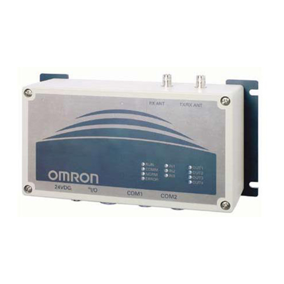
V720-series Electromagnetic Inductive RFID System
Brand:
Omron
| Category:
Other
| Size: 2.15 MB
Table of Contents
Features
4
Table of Contents
9
Section 1
13
Features and System Configuration
13
Features
14
System Configuration
15
Example of 1-To-1 System Configuration
15
Example of 1-To-N System Configuration
16
Section 2
17
Specifications and Performance
17
Reader/Writer (V720S-BC5D4A)
18
Nomenclature
18
Names of Connector Terminals
19
Specifications
20
General Specifications
20
Performance Specifications
20
Reader/Writer Communications Specifications
21
I/O Specifications
22
Host Communications Specifications
23
Dimensions
24
Cable (Sold Separately)
25
General Specifications
25
Dimensions
25
Memory Map of Tag
27
I.CODE SLI Chip
27
I.code1Chip
30
Section 3
32
Functions
32
Operating Mode
33
Chip Operating Mode
33
Online Mode /Offline Mode
33
Communication Mode
34
Single Access
34
FIFO Access
34
Communication Modes
34
Multiple Access
35
Selective Access
35
Fast Read Access: I.CODE1 Mode Only
36
Memory Check Function I.CODE1 Mode Only
37
Usage
37
Lock Function
38
Discriminating Access to Tag Function
39
External I/O Function
40
External Input
40
External Output
40
EAS Function
41
Duplicate Communication Protecting Function
42
Duplicate Communication Protecting Function [Ver1.20 or Higher]
42
Section 4
43
From Start-Up to Operation
43
Operation of Reader/Writer
44
Offline Mode
44
Online Mode
45
Trial Operation
46
Reader/Writer Setting
47
Host Communications Setting (COM Port Setting)
47
Chip Operating Mode Setting
48
Command Processing Procedure Setting
49
Antenna and Tag Communications Setting
50
Offline Mode Setting
51
Initialization of Settings
51
Fixing of Settings
51
Installation Environment
52
Installation
52
Mounting Method
53
Mounting Dimensional Drawing
53
Wiring Method
54
Power Supply and Grounding Wires
54
Host Communications Cabling
55
RS-232C Interface Cabling
55
Interface Cabling
57
Assembly of Connector
60
Assembly of Host Communications Connector and I/O Connector
60
Assembly of Connector
61
Section 5
62
Control from Host
62
Control by Commands
64
Command-Response Flow
64
ACK/NACK Control
65
Control Procedures for each Communication Mode
66
Single Access
66
Single Trigger Mode
66
Single Auto Mode
66
Single Repeat Mode: ISO Mode
67
Polling Auto Read
68
FIFO Access
69
FIFO Trigger Mode
69
FIFO Auto Mode
70
FIFO Repeat Mode
71
Multiple Access
72
Multiple Trigger Mode
72
Multiple Repeat Mode
74
Selective Access
75
ISO Mode
75
I.CODE1 Mode
77
I.CODE1 Mode
78
Specifying a Tag Code: I.CODE1 Mode
79
Command-Response Format
79
Command Frame Structure
80
Response Frame Structure
80
Command Code List
81
Specifying a Data Code
85
ISO Mode
86
Response Code List
86
I.CODE1 Mode
87
Example BCC Calculation
88
Communication Commands
89
Read (RD)
89
Write (WT)
90
Read (RD)-Tag Detection: I.CODE1 Mode Only
92
Read (RD)-UID Select/Specified Tag
93
Write (WT)-UID Select/Specified Tag
94
Read (RD)-Fast Read Access: I.CODE1 Mode Only
95
Polling Single Auto Read (PR)
96
Polling Single Auto Write (PW)
97
Polling Check (PC)
98
Polling End (PE)
99
Memory Check (MC): I.CODE1 Mode Only
100
Memory Calculation (MK): I.CODE1 Mode Only
100
System Command
101
System Read (SR): ISO Mode Only
101
System Write (SW): ISO Mode Only
102
System Lock (SL): ISO Mode Only
103
Read (RD)-SNR Read: I.CODE1 Mode Only
104
EAS Setting (ES): I.CODE1 Mode Only
105
Quietbit Setting (QB): I.CODE1 Mode Only
105
Lock Setting (LK): ISO Mode
106
Lock Setting Read (LR): ISO Mode Only
107
Lock Setting (LK): I.CODE1 Mode
108
EAS Check (EA)
109
Reader/Writer Control Commands
110
Stop (ST)
110
Reset (XZ)
110
Ack(Ak)
110
Nack(Nk)
110
I/O Control Command (CC)
111
Test (TS)
111
Version (VS)
112
Setting Command
113
Reader/Writer AFI Enable/Disable Changeover (AE): ISO Mode Only
113
Reader/Writer AFI Value Setting (AF): ISO Mode Only
113
Reader/Writer Family Code Setting (FC): I.CODE1 Mode
114
Reader/Writer Application ID Setting (AI): I.CODE1 Mode
114
UID/SNR Addition Setting (SN)
115
Node Number Setting(NN)
116
Communications Port Setting(CP)
117
Communications Type Setting (CT)
119
Tag Communications Mode Setting(CM)
119
Antenna Changeover(AC)
120
Terminal Resistance Setting (TM)
120
Offline Mode Setting (FL)
121
Set Value Initialization (IS)
122
Set Value Writing (EW)
122
Chip Operating Mode Switch (TY)
123
Duplicate Communication Protecting Function Setting (MX) [Ver1.20 and Higher]
124
I/O Automatic Changeover Setting (CA) [Ver1.20 and Higher]
125
Other Commands
126
Command Undefined Response
126
Command Connection: I.CODE1 Mode Only
127
Section 6
129
Startup and Full Operation
129
Error Types and Diagnostic Functions
130
Errors and Remedies
131
Maintenance and Inspection
132
Troubleshooting
133
Check Flowchart
133
Check Items for each Response Code
138
Section 7
139
Reference Data
139
Turn Around Time and Communication Time
141
ISO Mode - Communication Time of I.CODE SLI Chip
142
Turn Around Time (TAT) Calculation Method
143
Calculating the Speed of the Tag
144
Section 8
145
Appendix
145
Appendix 1 Accessories
146
Appendix 2 JIS8 Code Table (ASCII Code Table)
147
Advertisement
Advertisement
Related Products
Omron V720S-BC5D4A-US
Omron V720S-HMU01
Omron V720 Series
Omron V750-BA50C04-US
Omron V700-D23P41
Omron V700-L21
Omron V700-HMD11
Omron V700-H02
Omron V700-CD1D
Omron V700-HMD11-1
Omron Categories
Blood Pressure Monitor
Controller
Accessories
Switch
Inverter
More Omron Manuals
Login
Sign In
OR
Sign in with Facebook
Sign in with Google
Upload manual
Upload from disk
Upload from URL