Table of Contents
Advertisement
Quick Links
Advertisement
Table of Contents

Related Manuals for IEI Technology WAFER-ULT-i1


Summary of Contents for IEI Technology WAFER-ULT-i1
- Page 1 WAFER-ULT/ULT2-i1 3.5" SBC MODEL: WAFER-ULT/ULT2-i1 3.5” SBC with Intel® 4 Generation Mobile Core™ i7/i5/i3 or Celeron® ULT SoC, Dual PCIe GbE, VGA, LVDS, iDP, USB 3.0, SATA 6Gb/s, PCIe Mini, iRIS-1010, HD Audio and RoHS User Manual Page i Rev. 1.11 – July 28, 2016...
- Page 2 WAFER-ULT/ULT2-i1 3.5" SBC Revision Date Version Changes July 28, 2016 1.11 Added Figure 3-30: LAN Connector August 31, 2015 1.10 Updated for R11 version July 9, 2014 1.00 Initial release Page ii...
- Page 3 WAFER-ULT/ULT2-i1 3.5" SBC Copyright COPYRIGHT NOTICE The information in this document is subject to change without prior notice in order to improve reliability, design and function and does not represent a commitment on the part of the manufacturer. In no event will the manufacturer be liable for direct, indirect, special, incidental, or consequential damages arising out of the use or inability to use the product or documentation, even if advised of the possibility of such damages.
- Page 4 WAFER-ULT/ULT2-i1 3.5" SBC Manual Conventions WARNING Warnings appear where overlooked details may cause damage to the equipment or result in personal injury. Warnings should be taken seriously. CAUTION Cautionary messages should be heeded to help reduce the chance of losing data or damaging the product. NOTE These messages inform the reader of essential but non-critical information.
-
Page 5: Table Of Contents
WAFER-ULT/ULT2-i1 3.5" SBC Table of Contents 1 INTRODUCTION......................1 1.1 I ......................2 NTRODUCTION 1.2 B ........................2 ENEFITS 1.3 M ....................3 ODEL ARIATIONS 1.4 F ........................3 EATURES 1.5 C ......................4 ONNECTORS 1.6 D ....................... 5 IMENSIONS 1.7 D ........................ - Page 6 WAFER-ULT/ULT2-i1 3.5" SBC 3.2.9 Internal DisplayPort Connector ..............27 3.2.10 IPMI LED Connector..................28 3.2.11 iRIS Module Slot..................... 28 3.2.12 Keyboard and Mouse Connector ..............29 3.2.13 LAN LED Connectors ..................31 3.2.14 LVDS Backlight Control Connector............... 31 3.2.15 LVDS Connector .................... 32 3.2.16 PCIe Mini Card Slot ..................
- Page 7 WAFER-ULT/ULT2-i1 3.5" SBC 4.7.3 Clear CMOS Button..................60 4.7.4 LVDS Panel Type Selection................61 4.7.5 LVDS Voltage Selection..................62 4.8 C .................... 63 HASSIS NSTALLATION 4.8.1 Heat Sink Enclosure..................63 4.8.2 Motherboard Installation................. 64 4.9 I ............65 NTERNAL ERIPHERAL EVICE ONNECTIONS 4.9.1 AT/ATX Power Connection ................
- Page 8 WAFER-ULT/ULT2-i1 3.5" SBC 5.3.9 Intel(R) Rapid Start Technology............... 94 5.3.10 USB Configuration..................95 5.3.11 iEi Feature...................... 96 5.4 C ........................97 HIPSET 5.4.1 System Agent (SA) Configuration ..............97 5.4.1.1 Graphics Configuration................98 5.4.1.2 Memory Configuration ................101 5.4.2 PCH-IO Configuration .................. 101 5.4.2.1 PCI Express Configuration ..............
- Page 9 WAFER-ULT/ULT2-i1 3.5" SBC E WATCHDOG TIMER....................144 F HAZARDOUS MATERIALS DISCLOSURE............147 Page ix...
- Page 10 WAFER-ULT/ULT2-i1 3.5" SBC List of Figures Figure 1-1: WAFER-ULT/ULT2-i1....................2 Figure 1-2: Connectors ........................4 Figure 1-3: WAFER-ULT/ULT2-i1 Dimensions (mm) ..............6 Figure 1-4: Data Flow Diagram......................7 Figure 3-1: Peripheral Interface Connectors ................17 Figure 3-2: Power Connector Location ..................20 Figure 3-3: 5 V SATA Power Connector Locations ..............21 Figure 3-4: Audio Connector Location ..................22 Figure 3-5: Battery Connector Location..................23 Figure 3-6: Buzzer Connector Location ..................24...
- Page 11 WAFER-ULT/ULT2-i1 3.5" SBC Figure 3-27: System Fan Connector Location................44 Figure 3-28: USB 2.0 Connector Location .................45 Figure 3-29: External Interface Connectors................45 Figure 3-30: LAN Connector......................46 Figure 3-31: Serial Port ........................47 Figure 3-32: VGA Connector .......................48 Figure 4-1: SO-DIMM Installation ....................52 Figure 4-2: Removing the Retention Screw for the iRIS-1010 Module........53 Figure 4-3: Inserting the iRIS-1010 Module into the Slot at an Angle ........53 Figure 4-4: Securing the iRIS-1010 Module ................54...
- Page 12 WAFER-ULT/ULT2-i1 3.5" SBC Figure 6-5: Chipset Driver Installation Finish Screen............116 Figure 6-6: Graphics Driver Welcome Screen ................ 117 Figure 6-7: Graphics Driver License Agreement..............118 Figure 6-8: Graphics Driver Read Me File ................118 Figure 6-9: Graphics Driver Setup Operations ............... 119 Figure 6-10: Graphics Driver Installation Finish Screen ............
- Page 13 WAFER-ULT/ULT2-i1 3.5" SBC List of Tables Table 1-1: Model Variations ......................3 Table 1-2: WAFER-ULT/ULT2-i1 Specifications.................10 Table 2-1: Packing List.........................14 Table 2-2: Optional Items......................15 Table 3-1: Peripheral Interface Connectors ................19 Table 3-2: External Peripheral Connectors................19 Table 3-3: Power Connector Pinouts..................20 Table 3-4: 5 V SATA Power Connector Pinouts ................21 Table 3-5: Audio Connector Pinouts ..................22 Table 3-6: Battery Connector Pinouts ..................23 Table 3-7: Buzzer Connector Pinouts..................24...
- Page 14 WAFER-ULT/ULT2-i1 3.5" SBC Table 3-27: System Fan Connector Pinouts ................44 Table 3-28: USB 2.0 Connector Pinouts ..................45 Table 3-29: LAN Pinouts ......................46 Table 3-30: USB 3.0 Port Pinouts....................47 Table 3-31: Serial Port Pinouts....................47 Table 3-32: VGA Connector Pinouts...................48 Table 4-1: DC 5V Jumper Settings ....................59 Table 4-2: DC 5V Jumper Pinouts ....................59 Table 4-3: AT/ATX Power Mode Switch Settings...............60 Table 4-4: LVDS Panel Type Selection ..................61...
- Page 15 WAFER-ULT/ULT2-i1 3.5" SBC BIOS Menus BIOS Menu 1: Main ........................76 BIOS Menu 2: Advanced ......................77 BIOS Menu 3: CPU Configuration ....................78 BIOS Menu 4: ACPI Settings .......................80 BIOS Menu 5: AMT Configuration....................81 BIOS Menu 6: F81866 Super IO Configuration ................82 BIOS Menu 7: Serial Port n Configuration Menu...............82 BIOS Menu 8: iWDD H/W Monitor ....................87 BIOS Menu 9: Smart Fan Mode Configuration ................87...
-
Page 16: Introduction
WAFER-ULT/ULT2-i1 3.5" SBC Chapter Introduction Page 1... -
Page 17: Introduction
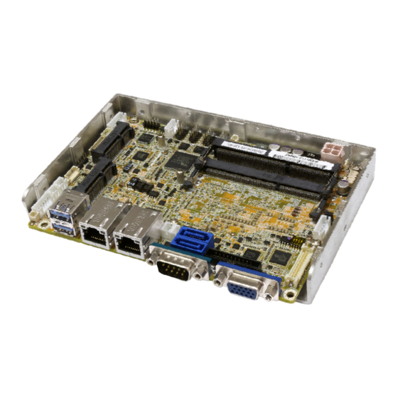
WAFER-ULT/ULT2-i1 3.5" SBC 1.1 Introduction Figure 1-1: WAFER-ULT/ULT2-i1 The WAFER-ULT/ULT2-i1 3.5” SBC is an Intel® 4 generation mobile ULT SoC platform that supports two 1600/1333 MHz dual-channel DDR3L SO-DIMMs up to 16 GB. The WAFER-ULT/ULT2-i1 provides two GbE interfaces through the Intel® I218-LM (with Intel®... -
Page 18: Model Variations
WAFER-ULT2-i1-C-R11 Intel® Celeron® 3765U (1.9 GHz, dual-core, 2 MB cache, TDP=15W) Intel® 4th Generation Mobile ULT On-Board SoC WAFER-ULT-i1-i7-R11 Intel® Core™ i7-4650U (1.7 GHz, dual-core, 4 MB cache, TDP=15W) WAFER-ULT-i1-i5-R11 Intel® Core™ i5-4300U (1.9 GHz, dual-core, 3 MB cache, TDP=15W) WAFER-ULT-i1-i3-R11 Intel®... -
Page 19: Connectors
WAFER-ULT/ULT2-i1 3.5" SBC 1.5 Connectors The connectors on the WAFER-ULT/ULT2-i1 are shown in the figure below. Figure 1-2: Connectors Page 4... -
Page 20: Dimensions
WAFER-ULT/ULT2-i1 3.5" SBC 1.6 Dimensions The main dimensions of the WAFER-ULT/ULT2-i1 are shown in the diagram below. Page 5... -
Page 21: Figure 1-3: Wafer-Ult/Ult2-I1 Dimensions (Mm)
WAFER-ULT/ULT2-i1 3.5" SBC Figure 1-3: WAFER-ULT/ULT2-i1 Dimensions (mm) Page 6... -
Page 22: Data Flow
WAFER-ULT/ULT2-i1 3.5" SBC 1.7 Data Flow Figure 1-4 shows the data flow between the system chipset, the CPU and other components installed on the motherboard. Figure 1-4: Data Flow Diagram Page 7... -
Page 23: Technical Specifications
WAFER-ULT/ULT2-i1 3.5" SBC 1.8 Technical Specifications The WAFER-ULT/ULT2-i1 technical specifications are listed below. Specifications/Model WAFER-ULT/ULT2-i1 3.5” Form Factor Intel® 5th generation mobile ULT on-board SoC: Intel® Core™ i7-5650U (2.2 GHz, dual-core, 4 MB cache, TDP=15W) Intel® Core™ i5-5350U (1.8 GHz, dual-core, 3 MB cache, TDP=15W) Intel®... - Page 24 WAFER-ULT/ULT2-i1 3.5" SBC Specifications/Model WAFER-ULT/ULT2-i1 Realtek ALC662 HD Audio codec Audio One audio connector (10-pin header) Super I/O Controller Fintek F81866 Watchdog Timer Software programmable, supports 1~255 sec. system reset UEFI BIOS BIOS Expansion One full-size/half-size PCIe Mini card slot with mSATA support IPMI 2.0 One iRIS-1010 module slot One 2-pin header for IPMI LED...
-
Page 25: Table 1-2: Wafer-Ult/Ult2-I1 Specifications
WAFER-ULT/ULT2-i1 3.5" SBC Specifications/Model WAFER-ULT/ULT2-i1 +12V@2.72A (Intel® Core™ i5-4300U on-board SoC with two 8 GB Power Consumption 1600 MHz DDR3L SO-DIMMs) Operating -10ºC ~ 60ºC Temperature Storage -20ºC ~ 70ºC Temperature Operating Humidity 5% ~ 95% (non-condensing) Dimensions 146 mm x 102 mm Weight (GW/NW) 600 g/250 g Table 1-2: WAFER-ULT/ULT2-i1 Specifications... -
Page 26: Packing List
WAFER-ULT/ULT2-i1 3.5" SBC Chapter Packing List Page 11... -
Page 27: Anti-Static Precautions
WAFER-ULT/ULT2-i1 3.5" SBC 2.1 Anti-static Precautions WARNING! Static electricity can destroy certain electronics. Make sure to follow the ESD precautions to prevent damage to the product, and injury to the user. Make sure to adhere to the following guidelines: Wear an anti-static wristband: Wearing an anti-static wristband can prevent electrostatic discharge. -
Page 28: Packing List
WAFER-ULT/ULT2-i1 3.5" SBC 2.3 Packing List NOTE: If any of the components listed in the checklist below are missing, do not proceed with the installation. Contact the IEI reseller or vendor the WAFER-ULT/ULT2-i1 was purchased from or contact an IEI sales representative directly by sending an email to ales@ieiworld.com. -
Page 29: Optional Items
WAFER-ULT/ULT2-i1 3.5" SBC Quantity Item and Part Number Image One Key Recovery CD Quick installation guide Table 2-1: Packing List 2.4 Optional Items These optional items are available. Item and Part Number Image iRIS-1010 module, IPMI 2.0 adapter card with AST1010 BMC chip (without KVM over IP function) for PCIe Mini socket interface (P/N: iRIS-1010-R10) -
Page 30: Table 2-2: Optional Items
WAFER-ULT/ULT2-i1 3.5" SBC Item and Part Number Image DisplayPort to HDMI converter board for IEI iDP connector (P/N: DP-HDMI-R10) DisplayPort to VGA converter board for IEI iDP connector (P/N: DP-VGA-R10) DisplayPort to DVI-D converter board for IEI iDP connector (P/N: DP-DVI-R10) DisplayPort to DisplayPort converter board for IEI iDP connector (P/N: DP-DP-R10) -
Page 31: Connectors
WAFER-ULT/ULT2-i1 3.5" SBC Chapter Connectors Page 16... -
Page 32: Peripheral Interface Connectors
WAFER-ULT/ULT2-i1 3.5" SBC 3.1 Peripheral Interface Connectors This chapter details all the peripheral interface connectors. 3.1.1 WAFER-ULT/ULT2-i1 Layout The figure below shows all the peripheral interface connectors. Figure 3-1: Peripheral Interface Connectors Page 17... -
Page 33: Peripheral Interface Connectors
WAFER-ULT/ULT2-i1 3.5" SBC 3.1.2 Peripheral Interface Connectors The table below lists all the connectors on the board. Connector Type Label 4-pin Molex power +12V power connector connector SATA_PWR1, 5 V SATA power connectors 2-pin wafer SATA_PWR2 Audio connector 10-pin header AUDIO1 Battery connector 2-pin wafer... -
Page 34: External Interface Panel Connectors
WAFER-ULT/ULT2-i1 3.5" SBC Connector Type Label Serial port, RS-422/485 4-pin wafer COM4 SMBus connector 4-pin wafer 204-pin DDR3L SO-DIMM slots DIMM1, DIMM2 SO-DIMM slot SPI flash connector 6-pin wafer SPI1 System fan connector 4-pin wafer FAN1 USB 2.0 connector 8-pin header USB1 Table 3-1: Peripheral Interface Connectors 3.1.3 External Interface Panel Connectors... -
Page 35: Power Connector
WAFER-ULT/ULT2-i1 3.5" SBC 3.2.1 +12V Power Connector CN Label: 4-pin Molex power connector, p=4.2 mm CN Type: CN Location: See Figure 3-2 CN Pinouts: See Table 3-3 The power connector is connected to an external power supply and supports +12V power input. -
Page 36: Sata Power Connectors
WAFER-ULT/ULT2-i1 3.5" SBC 3.2.2 5 V SATA Power Connectors CN Label: SATA_PWR1, SATA_PWR2 2-pin wafer, p=2 mm CN Type: CN Location: See Figure 3-3 CN Pinouts: See Table 3-4 Use the 5 V SATA power connectors to connect to SATA device power connections. Figure 3-3: 5 V SATA Power Connector Locations Description Table 3-4: 5 V SATA Power Connector Pinouts... -
Page 37: Battery Connector
WAFER-ULT/ULT2-i1 3.5" SBC Figure 3-4: Audio Connector Location Description Description LINE1_R LINEOUT1R AUD_GND AUD_GND LINE1_L LINEOUT1L AUD_GND AUD_GND FMIC1_R FMIC1_L Table 3-5: Audio Connector Pinouts 3.2.4 Battery Connector CAUTION: Risk of explosion if battery is replaced by an incorrect type. Only certified engineers should replace the on-board battery. -
Page 38: Buzzer Connector
WAFER-ULT/ULT2-i1 3.5" SBC This is connected to the system battery. The battery provides power to the system clock to retain the time when power is turned off. Figure 3-5: Battery Connector Location Description VBATT Table 3-6: Battery Connector Pinouts 3.2.5 Buzzer Connector CN Label: 2-pin wafer, p=1.25 mm CN Type:... -
Page 39: Chassis Intrusion Connector
WAFER-ULT/ULT2-i1 3.5" SBC Figure 3-6: Buzzer Connector Location Description +V5S Table 3-7: Buzzer Connector Pinouts 3.2.6 Chassis Intrusion Connector CN Label: CHASSIS1 CN Type: 2-pin header, p=2 mm CN Location: F igure 3-7 CN Pinouts: See Table 3-8 The chassis intrusion connector is for a chassis intrusion detection sensor or switch that detects if a chassis component is removed or replaced. -
Page 40: Digital I/O Connector
WAFER-ULT/ULT2-i1 3.5" SBC Description +3.3VSB CHASSIS OPEN Table 3-8: Chassis Intrusion Connector Pinouts 3.2.7 Digital I/O Connector CN Label: DIO1 CN Type: 10-pin header, p=2 mm CN Location: See Figure 3-8 CN Pinouts: See Table 3-9 The digital I/O connector provides programmable input and output for external devices. The digital I/O provides 4-bit output and 4-bit input. -
Page 41: Ec Debug Connector
WAFER-ULT/ULT2-i1 3.5" SBC Description Description Input 3 Input 2 Input 1 Input 0 Table 3-9: Digital I/O Connector Pinouts 3.2.8 EC Debug Connector CN Label: CN Type: 2-pin header, p=2 mm CN Location: See Figure 3-9 CN Pinouts: See Table 3-10 The chassis intrusion connector is for a chassis intrusion detection sensor or switch that detects if a chassis component is removed or replaced. -
Page 42: Internal Displayport Connector
WAFER-ULT/ULT2-i1 3.5" SBC 3.2.9 Internal DisplayPort Connector CN Label: 20-pin box header, p=2 mm CN Type: CN Location: See Figure 3-10 CN Pinouts: See Table 3-11 The DisplayPort connector supports HDMI, LVDS, VGA, DVI and DisplayPort graphics interfaces with up to 3840x2160 resolution. Figure 3-10: Internal DisplayPort Connector Location Description Description... -
Page 43: Ipmi Led Connector
WAFER-ULT/ULT2-i1 3.5" SBC 3.2.10 IPMI LED Connector CN Label: ID_LED1 2-pin wafer, p=2 mm CN Type: CN Location: See Figure 3-11 CN Pinouts: See Table 3-12 The IPMI LED connector is used to connect to the IPMI LED indicator on the chassis. Figure 3-11: IPMI LED Connector Location Description ID_LED+... -
Page 44: Keyboard And Mouse Connector
WAFER-ULT/ULT2-i1 3.5" SBC Figure 3-12: iRIS Module Slot Location WARNING: The iRIS module slot is designed to install the iRIS-1010 module only. DO NOT install other modules into the iRIS module slot. Doing so may cause damage to the WAFER-ULT/ULT2-i1. 3.2.12 Keyboard and Mouse Connector CN Label: KB_MS1... -
Page 45: Figure 3-13: Keyboard And Mouse Connector Location
WAFER-ULT/ULT2-i1 3.5" SBC Figure 3-13: Keyboard and Mouse Connector Location Description Mouse Data Mouse Clock Keyboard Data Keyboard Clock Table 3-13: Keyboard and Mouse Connector Pinouts Page 30... -
Page 46: Lan Led Connectors
WAFER-ULT/ULT2-i1 3.5" SBC 3.2.13 LAN LED Connectors CN Label: LED_LAN1, LED_LAN2 2-pin header, p=2 mm CN Type: CN Location: See Figure 3-14 CN Pinouts: See Table 3-14 The LAN LED connectors are used to connect to the LAN LED indicators on the chassis to indicate users the link activities of the two LAN ports. -
Page 47: Lvds Connector
WAFER-ULT/ULT2-i1 3.5" SBC The backlight control connector provides the backlight on the LCD display connected to the WAFER-ULT/ULT2-i1 with +12V of power. Figure 3-15: LVDS Backlight Control Connector Location Description LCD_BKLTCTL GROUND +12V GROUND BACKLIGHT ENABLE Table 3-15: LVDS Backlight Control Connector Pinouts 3.2.15 LVDS Connector CN Label: LVDS1... -
Page 48: Figure 3-16: Lvds Connector Location
WAFER-ULT/ULT2-i1 3.5" SBC Figure 3-16: LVDS Connector Location Description Description LVDS_A_TX0-P LVDS_A _TX0-N LVDS_A_TX1-P LVDS_A _TX1-N LVDS_A_TX2-P LVDS_A _TX2-N LVDS_A_TXCLK-P LVDS_A _TXCLK-N LVDS_A_TX3-P LVDS_A _TX3-N LVDS_B _TX0-P LVDS_B _TX0-N LVDS_B _TX1-P LVDS_B _TX1-N LVDS_B _TX2-P LVDS_B _TX2-N LVDS_B _TXCLK-P LVDS_B _TXCLK-N LVDS_B _TX3-P LVDS_B _TX3-N +LCD Vcc... -
Page 49: Pcie Mini Card Slot
WAFER-ULT/ULT2-i1 3.5" SBC 3.2.16 PCIe Mini Card Slot CN Label: M_PCIE2 PCIe Mini card slot CN Type: CN Location: See Figure 3-17 CN Pinouts: See Table 3-17 The PCIe Mini card slot enables a full-size/half-size PCIe Mini card expansion module to be connected to the board. -
Page 50: Power And Hdd Led Connector
WAFER-ULT/ULT2-i1 3.5" SBC Description Description PCIRST# PCIE_RXN VCC3 PCIE_RXP 1.5V SMBCLK PCIE_TXN SMBDATA PCIE_TXP USBD- USBD+ VCC3 VCC3 1.5V M-SATA Detect VCC3 Table 3-17: PCIe Mini Card Slot Pinouts 3.2.17 Power and HDD LED Connector CN Label: CN Type: 6-pin wafer, p=2 mm CN Location: See Figure 3-18 See Table 3-18... -
Page 51: Power Button Connector
WAFER-ULT/ULT2-i1 3.5" SBC Figure 3-18: Power and HDD LED Connector Location Function Description PWRLED Power LED HDD LED -HDLED Table 3-18: Power and HDD LED Connector Pinouts 3.2.18 Power Button Connector CN Label: PWR_BTN1 CN Type: 2-pin wafer, p=2 mm CN Location: See Figure 3-19 CN Pinouts:... -
Page 52: Reset Button Connector
WAFER-ULT/ULT2-i1 3.5" SBC Figure 3-19: Power Button Connector Location Description PWRBTSW# Table 3-19: Power Button Connector Pinouts 3.2.19 Reset Button Connector CN Label: RST_BTN1 CN Type: 2-pin wafer, p=2 mm CN Location: See Figure 3-20 See Table 3-20 CN Pinouts: The reset button connector is connected to a reset switch on the system chassis to enable users to reboot the system when the system is turned on. -
Page 53: Sata 6Gb/S Connectors
WAFER-ULT/ULT2-i1 3.5" SBC Description SYSRST Table 3-20: Reset Button Connector Pinouts 3.2.20 SATA 6Gb/s Connectors CN Label: SATA1, SATA2 CN Type: 7-pin SATA drive connector CN Location: See Figure 3-21 CN Pinouts: See Table 3-21 The SATA drive connectors can be connected to SATA drives and support up to 6Gb/s data transfer rate. -
Page 54: Serial Port Connector, Rs-232
WAFER-ULT/ULT2-i1 3.5" SBC Description Table 3-21: SATA 6Gb/s Drive Connector Pinouts 3.2.21 Serial Port Connector, RS-232 CN Label: COM2, COM3 CN Type: 10-pin header, p=2 mm CN Location: See Figure 3-22 CN Pinouts: See Table 3-22 The 10-pin serial port connector provides one RS-232 serial communications channel. The COM serial port connector can be connected to an external RS-232 serial port device. -
Page 55: Serial Port Connector, Rs-422/485
WAFER-ULT/ULT2-i1 3.5" SBC Description Description DATA TERMINAL READY (DTR) RING INDICATOR (RI) Table 3-22: RS-232 Serial Port Connector Pinouts 3.2.22 Serial Port Connector, RS-422/485 CN Label: COM4 CN Type: 4-pin wafer, p=2 mm CN Location: See Figure 3-23 CN Pinouts: See Table 3-23 This connector provides RS-422 or RS-485 communications. -
Page 56: Smbus Connector
WAFER-ULT/ULT2-i1 3.5" SBC Use the optional RS-422/485 cable to connect to a serial device. The pinouts of the DB-9 connector are listed below. RS-422 Pinouts RS-485 Pinouts Table 3-24: DB-9 RS-422/485 Pinouts 3.2.23 SMBus Connector CN Label: CN Type: 4-pin wafer, p=1.25 mm CN Location: See Figure 3-24 CN Pinouts:... -
Page 57: So-Dimm Slots
WAFER-ULT/ULT2-i1 3.5" SBC Description SMB_CLK Table 3-25: SMBus Connector Pinouts 3.2.24 SO-DIMM Slots CN Label: DIMM1, DIMM2 CN Type: 204-pin DDR3L SO-DIMM slot CN Location: See Figure 3-25 The SO-DIMM slots are for installing the SO-DIMMs on the system. Figure 3-25: SO-DIMM Slot Locations Page 42... -
Page 58: Spi Flash Connector
WAFER-ULT/ULT2-i1 3.5" SBC 3.2.25 SPI Flash Connector CN Label: SPI1 6-pin wafer, p=1.25 mm CN Type: CN Location: See Figure 3-26 CN Pinouts: See Table 3-26 The SPI flash connector is used to flash the SPI ROM. Figure 3-26: SPI Flash Connector Location Description SPI_VCC SPI_2N_CS#... -
Page 59: Usb 2.0 Connector
WAFER-ULT/ULT2-i1 3.5" SBC The fan connector attaches to a system cooling fan. Figure 3-27: System Fan Connector Location Description +12V FANIO Table 3-27: System Fan Connector Pinouts 3.2.27 USB 2.0 Connector CN Label: USB1 CN Type: 8-pin header, p=2 mm CN Location: See Figure 3-28 CN Pinouts:... -
Page 60: External Interface Connectors
WAFER-ULT/ULT2-i1 3.5" SBC Figure 3-28: USB 2.0 Connector Location Description Description USB_VCC DATA- DATA+ DATA+ DATA- USB_VCC Table 3-28: USB 2.0 Connector Pinouts 3.3 External Interface Connectors The figure below shows the external peripheral interface connector (EPIC) panel. The EPIC panel consists of the following: Figure 3-29: External Interface Connectors Page 45... -
Page 61: Ethernet Connectors
WAFER-ULT/ULT2-i1 3.5" SBC 3.3.1 Ethernet Connectors CN Label: LAN1, LAN2 RJ-45 CN Type: CN Location: See Figure 3-29 CN Pinouts: See Table 3-29 Each LAN connector connects to a local network. Figure 3-30: LAN Connector Description Description LAN_MDI0+ LAN_MDI2+ LAN_MDI0- LAN_MDI2- LAN_MDI1+ LAN_MDI3+... -
Page 62: Serial Port Connector (Com1)
WAFER-ULT/ULT2-i1 3.5" SBC Description Description Table 3-30: USB 3.0 Port Pinouts 3.3.3 Serial Port Connector (COM1) CN Label: COM1 CN Type: DB-9 CN Location: See Figure 3-29 See Table 3-31 CN Pinouts: The serial port connects to an RS-232 serial communications device. Description Description DATA CARRIER DETECT (DCD) -
Page 63: Vga Connector
WAFER-ULT/ULT2-i1 3.5" SBC 3.3.4 VGA Connector CN Label: VGA1 15-pin female CN Type: CN Location: See Figure 3-29 CN Pinouts: See Figure 3-32 and Table 3-32 The VGA connector connects to a monitor that accepts a standard VGA input. Description Description GREEN BLUE... -
Page 64: Installation
WAFER-ULT/ULT2-i1 3.5" SBC Chapter Installation Page 49... -
Page 65: Anti-Static Precautions
WAFER-ULT/ULT2-i1 3.5" SBC 4.1 Anti-static Precautions WARNING: Failure to take ESD precautions during the installation of the WAFER-ULT/ULT2-i1 may result in permanent damage to the WAFER-ULT/ULT2-i1 and severe injury to the user. Electrostatic discharge (ESD) can cause serious damage to electronic components, including the WAFER-ULT/ULT2-i1. - Page 66 WAFER-ULT/ULT2-i1 3.5" SBC WARNING: The installation instructions described in this manual should be carefully followed in order to prevent damage to the components and injury to the user. Before and during the installation please DO the following: Read the user manual: The user manual provides a complete description of the WAFER-ULT/ULT2-i1 installation instructions and configuration options.
-
Page 67: So-Dimm Installation
WAFER-ULT/ULT2-i1 3.5" SBC 4.3 SO-DIMM Installation To install a SO-DIMM, please follow the steps below and refer to Figure 4-1. Figure 4-1: SO-DIMM Installation Step 1: Locate the SO-DIMM socket. Place the board on an anti-static mat. Step 2: Align the SO-DIMM with the socket. Align the notch on the memory with the notch on the memory socket. -
Page 68: Figure 4-2: Removing The Retention Screw For The Iris-1010 Module
WAFER-ULT/ULT2-i1 3.5" SBC Figure 4-2: Removing the Retention Screw for the iRIS-1010 Module Step 3: Insert into the slot at an angle. Line up the notch on the module with the notch on the slot. Slide the iRIS-1010 module into the slot at an angle of about 20º (Figure 4-3). -
Page 69: Full-Size Pcie Mini Card Installation
WAFER-ULT/ULT2-i1 3.5" SBC Step 4: Secure the iRIS-1010 module. Secure the iRIS-1010 module with the retention screw previously removed (Figure 4-4). Figure 4-4: Securing the iRIS-1010 Module NOTE: After installing the iRIS-1010 module, use LAN2 port to establish a network connection. Please refer to Section 4.11 for IPMI setup procedures. -
Page 70: Figure 4-5: Removing The Retention Screw
WAFER-ULT/ULT2-i1 3.5" SBC Figure 4-5: Removing the Retention Screw Step 3: Insert into the socket at an angle. Line up the notch on the card with the notch on the slot. Slide the PCIe Mini card into the socket at an angle of about 20º (Figure 4-6). -
Page 71: Half-Size Pcie Mini Card Installation
WAFER-ULT/ULT2-i1 3.5" SBC Figure 4-7: Securing the Full-size PCIe Mini Card 4.6 Half-size PCIe Mini Card Installation The PCIe Mini card slot allows installation of either a full-size or half-size PCIe Mini card. To install a half-size PCIe Mini card, please follow the steps below. Step 1: Locate the PCIe Mini card slot. -
Page 72: Figure 4-8: Removing The Standoff
WAFER-ULT/ULT2-i1 3.5" SBC Figure 4-8: Removing the Standoff Step 4: Install the standoff to the screw hole for the half-size PCIe Mini card. Install the previously removed standoff to the screw hole for the half-size PCIe Mini card (Figure 4-9). Figure 4-9: Installing the Standoff Step 5: Insert into the socket at an angle. -
Page 73: System Configuration
WAFER-ULT/ULT2-i1 3.5" SBC Figure 4-10: Inserting the Half-size PCIe Mini Card into the Slot at an Angle Step 6: Secure the half-size PCIe Mini card. Secure the half-size PCIe Mini card with the retention screw previously removed (Figure 4-11). Step 0: Figure 4-11: Securing the Half-size PCIe Mini Card 4.7 System Configuration The system configuration is controlled by buttons, jumpers and switches. -
Page 74: Dc 5V Jumper For Lvds Backlight Dimming
WAFER-ULT/ULT2-i1 3.5" SBC 4.7.1 DC 5V Jumper for LVDS Backlight Dimming Jumper Label: LVDSBL_DC5V1 2-pin header, p=2 mm Jumper Type: Jumper Settings: See Table 4-1 Jumper Location: See Figure 4-12 The DC 5V jumper can be used to lock the LVDS backlight dimming voltage level at DC 5V. -
Page 75: At/Atx Power Mode Selection
WAFER-ULT/ULT2-i1 3.5" SBC 4.7.2 AT/ATX Power Mode Selection The AT and ATX power mode selection is made through the AT/ATX power mode switch which is shown in Figure 4-13. Figure 4-13: AT/ATX Power Mode Switch Location Setting Description ATX power mode (default) AT power mode Table 4-3: AT/ATX Power Mode Switch Settings 4.7.3 Clear CMOS Button... -
Page 76: Lvds Panel Type Selection
WAFER-ULT/ULT2-i1 3.5" SBC 4.7.4 LVDS Panel Type Selection Jumper Label: Jumper Type: DIP switch Jumper Settings: See Table 4-4 See Figure 4-15 Jumper Location: Selects the resolution of the LCD panel connected to the LVDS connector. * ON=0, OFF=1 SW1 (4-3-2-1) EDID Resolution Color Depth Channel... -
Page 77: Lvds Voltage Selection
WAFER-ULT/ULT2-i1 3.5" SBC 4.7.5 LVDS Voltage Selection WARNING: Permanent damage to the screen and WAFER-ULT/ULT2-i1 may occur if the wrong voltage is selected with this jumper. Please refer to the user guide that came with the monitor to select the correct voltage. Jumper Label: 3-pin header, p=2 mm Jumper Type:... -
Page 78: Chassis Installation
WAFER-ULT/ULT2-i1 3.5" SBC 4.8 Chassis Installation 4.8.1 Heat Sink Enclosure WARNING: Never run the WAFER-ULT/ULT2-i1 without the heat sink secured to the board. The heat sink ensures the system remains cool and does not need addition heat sinks to cool the system. WARNING: When running... -
Page 79: Motherboard Installation
WAFER-ULT/ULT2-i1 3.5" SBC 4.8.2 Motherboard Installation Each side of the heat sink enclosure has several screw holes allowing the WAFER-ULT/ULT2-i1 to be mounted into a chassis (please refer to Figure 1-3 for the detailed dimensions). The user can design or select a chassis that has screw holes matching up with the holes on the heat sink enclosure for installing the WAFER-ULT/ULT2-i1. -
Page 80: Internal Peripheral Device Connections
WAFER-ULT/ULT2-i1 3.5" SBC 4.9 Internal Peripheral Device Connections This section outlines the installation of peripheral devices to the on-board connectors. 4.9.1 AT/ATX Power Connection Follow the instructions below to connect the WAFER-ULT/ULT2-i1 to an AT or ATX power supply. WARNING: Disconnect the power supply power cord from its AC power source to prevent a sudden power surge to the WAFER-ULT/ULT2-i1. -
Page 81: Audio Kit Installation
WAFER-ULT/ULT2-i1 3.5" SBC Step 3: Connect Power Cable to Power Supply. Connect one of the 4-pin (1x4) Molex type power cable connectors to an AT/ATX power supply. See Figure 4-20. Figure 4-20: Connect Power Cable to Power Supply 4.9.2 Audio Kit Installation The Audio Kit that came with the WAFER-ULT/ULT2-i1 connects to the 10-pin audio connector on the WAFER-ULT/ULT2-i1. -
Page 82: Lvds Lcd Installation
WAFER-ULT/ULT2-i1 3.5" SBC Figure 4-21: Audio Kit Cable Connection Step 3: Connect the audio devices. Connect speakers to the line-out audio jack. Connect the output of an audio device to the line-in audio jack. Connect a microphone to the mic-in audio jack. 4.9.3 LVDS LCD Installation The WAFER-ULT/ULT2-i1 can be connected to a TFT LCD screen through the LVDS crimp connectors on the board. -
Page 83: Figure 4-22: Lvds Connector
WAFER-ULT/ULT2-i1 3.5" SBC WARNING: The diagram below is merely for illustration. The configuration and connection of the cables from the TFT LCD screen being installed may be different. Please refer to the installation manual that came with the TFT LCD screen. Figure 4-22: LVDS Connector Step 3: Locate the backlight inverter connector. -
Page 84: Sata Drive Connection
WAFER-ULT/ULT2-i1 3.5" SBC Figure 4-23: Backlight Inverter Connection 4.9.4 SATA Drive Connection The WAFER-ULT/ULT2-i1 is shipped with two SATA signal and power cables. To connect the SATA drive to the connectors, please follow the steps below. Step 1: Locate the SATA connector and the SATA power connector. The locations of the connectors are shown in Chapter 3. -
Page 85: Usb Cable Installation
WAFER-ULT/ULT2-i1 3.5" SBC Figure 4-24: SATA Drive Cable Connection Step 3: Connect the cable to the SATA disk. Connect the connector on the other end of the cable to the connector at the back of the SATA drive. See Figure 4-24. Step 4: To remove the SATA cable from the SATA connector, press the clip on the connector at the end of the cable. -
Page 86: Intel ® Amt Setup Procedure
WAFER-ULT/ULT2-i1 3.5" SBC Step 2: Align the connectors. Correctly align pin 1on the cable connector with pin 1 on the WAFER-ULT/ULT2-i1 USB connector. Step 3: Insert the cable connectors. Once the cable connector is properly aligned with the USB connector on the WAFER-ULT/ULT2-i1, connect the cable connector to the on-board connector. -
Page 87: Ipmi Setup Procedure
WAFER-ULT/ULT2-i1 3.5" SBC Step 4: Properly install the Intel® Management Engine Components drivers from the iAMT Driver & Utility directory in the driver CD. See Section 6.8. Step 5: Configure the Intel® Management Engine BIOS extension (MEBx). To get into the Intel®... -
Page 88: Bios
WAFER-ULT/ULT2-i1 3.5" SBC Chapter BIOS Page 73... -
Page 89: Introduction
WAFER-ULT/ULT2-i1 3.5" SBC 5.1 Introduction The BIOS is programmed onto the BIOS chip. The BIOS setup program allows changes to certain system settings. This chapter outlines the options that can be changed. NOTE: Some of the BIOS options may vary throughout the life cycle of the product and are subject to change without prior notice. -
Page 90: Getting Help
WAFER-ULT/ULT2-i1 3.5" SBC Function Page Up Move to the previous page Page Dn Move to the next page Main Menu – Quit and not save changes into CMOS Status Page Setup Menu and Option Page Setup Menu -- Exit current page and return to Main Menu General help, only for Status Page Setup Menu and Option Page Setup Menu Load previous values... -
Page 91: Main
WAFER-ULT/ULT2-i1 3.5" SBC 5.2 Main The Main BIOS menu (BIOS Menu 1) appears when the BIOS Setup program is entered. The Main menu gives an overview of the basic system information. Aptio Setup Utility – Copyright (C) 2015 American Megatrends, Inc. Main Advanced Chipset... -
Page 92: Advanced
WAFER-ULT/ULT2-i1 3.5" SBC The Main menu has two user configurable fields: System Date [xx/xx/xx] Use the System Date option to set the system date. Manually enter the day, month and year. System Time [xx:xx:xx] Use the System Time option to set the system time. Manually enter the hours, minutes and seconds. -
Page 93: Cpu Configuration
WAFER-ULT/ULT2-i1 3.5" SBC 5.3.1 CPU Configuration Use the CPU Configuration menu (BIOS Menu 3) to view detailed CPU specifications. Aptio Setup Utility – Copyright (C) 2015 American Megatrends, Inc. Advanced CPU Configuration Enabled for Windows XP and Linux (OS optimized Intel(R) Core(TM) i5-5350U CPU @ 1.80GHz for Hyper-Threading CPU Signature... - Page 94 WAFER-ULT/ULT2-i1 3.5" SBC Enable all cores in the processor package. EFAULT Enable one core in the processor package. Intel Virtualization Technology [Disabled] Use the Intel Virtualization Technology option to enable or disable virtualization on the system. When combined with third party software, Intel® Virtualization technology allows several OSs to run on the same system at the same time.
-
Page 95: Acpi Settings
WAFER-ULT/ULT2-i1 3.5" SBC 5.3.2 ACPI Settings The ACPI Settings menu (BIOS Menu 4) configures the Advanced Configuration and Power Interface (ACPI) options. Aptio Setup Utility – Copyright (C) 2015 American Megatrends, Inc. Advanced ACPI Settings Select the highest ACPI sleep state the system ACPI Sleep State [S1 (CPU Stop Clock)] will enter when the... -
Page 96: Amt Configuration
WAFER-ULT/ULT2-i1 3.5" SBC 5.3.3 AMT Configuration The AMT Configuration menu (BIOS Menu 5) allows the Intel® AMT options to be configured. Aptio Setup Utility – Copyright (C) 2015 American Megatrends, Inc. Advanced Intel AMT [Enabled] Enable/Disable Intel (R) Un-Configure ME [Disabled] Active Management Technology BIOS... -
Page 97: F81866 Super Io Configuration
WAFER-ULT/ULT2-i1 3.5" SBC 5.3.4 F81866 Super IO Configuration Use the F81866 Super IO Configuration menu (BIOS Menu 6) to set or change the configurations for the serial ports. Aptio Setup Utility – Copyright (C) 2015 American Megatrends, Inc. Advanced F81866 Super IO Configuration Set Parameters of Serial Port 1 (COMA) F81866 Super IO Chip... - Page 98 WAFER-ULT/ULT2-i1 3.5" SBC 5.3.4.1.1 Serial Port 1 Configuration Serial Port [Enabled] Use the Serial Port option to enable or disable the serial port. Disabled Disable the serial port Enabled Enable the serial port EFAULT Change Settings [Auto] Use the Change Settings option to change the serial port IO port address and interrupt address.
- Page 99 WAFER-ULT/ULT2-i1 3.5" SBC 5.3.4.1.2 Serial Port 2 Configuration Serial Port [Enabled] Use the Serial Port option to enable or disable the serial port. Disabled Disable the serial port Enable the serial port Enabled EFAULT Change Settings [Auto] Use the Change Settings option to change the serial port IO port address and interrupt address.
- Page 100 WAFER-ULT/ULT2-i1 3.5" SBC 5.3.4.1.3 Serial Port 3 Configuration Serial Port [Enabled] Use the Serial Port option to enable or disable the serial port. Disabled Disable the serial port Enable the serial port Enabled EFAULT Change Settings [Auto] Use the Change Settings option to change the serial port IO port address and interrupt address.
- Page 101 WAFER-ULT/ULT2-i1 3.5" SBC 5.3.4.1.4 Serial Port 4 Configuration Serial Port [Enabled] Use the Serial Port option to enable or disable the serial port. Disabled Disable the serial port Enable the serial port Enabled EFAULT Change Settings [Auto] Use the Change Settings option to change the serial port IO port address and interrupt address.
-
Page 102: Iwdd H/W Monitor
WAFER-ULT/ULT2-i1 3.5" SBC 5.3.5 iWDD H/W Monitor The iWDD H/W Monitor menu (BIOS Menu 8) contains the fan configuration submenu and displays the system temperatures and voltages. Aptio Setup Utility – Copyright (C) 2015 American Megatrends, Inc. Advanced PC Health Status Smart Fan Mode Select CPU temperature : +45C... -
Page 103: Rtc Wake Settings
WAFER-ULT/ULT2-i1 3.5" SBC CPU_FAN1 Smart Fan Control [Auto Mode] Use the CPU_FAN1 Smart Fan Control option to configure the system fan. The fan spins at the speed set in Manual PWM Manual Mode Setting settings. The fan adjusts its speed using Auto PWM Mode Auto Mode EFAULT settings. -
Page 104: Bios Menu 10: Rtc Wake Settings
WAFER-ULT/ULT2-i1 3.5" SBC Aptio Setup Utility – Copyright (C) 2015 American Megatrends, Inc. Advanced Wake system with Fixed Time [Disabled] Enable or disable System wake on alarm event. When enabled, System will wake on the date::hr::min::sec specified ---------------------- : Select Screen ↑... -
Page 105: Serial Port Console Redirection
WAFER-ULT/ULT2-i1 3.5" SBC 5.3.7 Serial Port Console Redirection The Serial Port Console Redirection menu (BIOS Menu 11) allows the console redirection options to be configured. Console redirection allows users to maintain a system remotely by re-directing keyboard input and text output through the serial port. Aptio Setup Utility –... - Page 106 WAFER-ULT/ULT2-i1 3.5" SBC NOTE: The following options are available in the Console Redirection Settings submenu when the Console Redirection option is enabled. Terminal Type [ANSI] Use the Terminal Type option to specify the remote terminal type. VT100 The target terminal type is VT100 VT100+ The target terminal type is VT100+ VT-UTF8...
- Page 107 WAFER-ULT/ULT2-i1 3.5" SBC Parity [None] Use the Parity option to specify the parity bit that can be sent with the data bits for detecting the transmission errors. None No parity bit is sent with the data bits. EFAULT Even The parity bit is 0 if the number of ones in the data bits is even.
-
Page 108: Sata Configuration
WAFER-ULT/ULT2-i1 3.5" SBC 5.3.8 SATA Configuration Use the SATA Configuration menu (BIOS Menu 12) to change and/or set the configuration of the SATA devices installed in the system. Aptio Setup Utility – Copyright (C) 2015 American Megatrends, Inc. Advanced SATA Controller(s) [Enabled] SATA Mode Selection [AHCI]... -
Page 109: Intel(R) Rapid Start Technology
WAFER-ULT/ULT2-i1 3.5" SBC 5.3.9 Intel(R) Rapid Start Technology Use the Intel(R) Rapid Start Technology (BIOS Menu 13) menu to configure Intel® Rapid Start Technology support. Aptio Setup Utility – Copyright (C) 2015 American Megatrends, Inc. Advanced Intel(R) Rapid Start Technology [Disabled] Enable or disable Intel(R) Rapid Start... -
Page 110: Usb Configuration
WAFER-ULT/ULT2-i1 3.5" SBC 5.3.10 USB Configuration Use the USB Configuration menu (BIOS Menu 14) to read USB configuration information and configure the USB settings. Aptio Setup Utility – Copyright (C) 2015 American Megatrends, Inc. Advanced USB Configuration Enables Legacy USB support. -
Page 111: Iei Feature
WAFER-ULT/ULT2-i1 3.5" SBC Enabled Legacy USB support enabled EFAULT Legacy USB support disabled Disabled Auto Legacy USB support disabled if no USB devices are connected 5.3.11 iEi Feature Use the iEi Feature menu (BIOS Menu 15) to configure One Key Recovery function. Aptio Setup Utility –... -
Page 112: Chipset
WAFER-ULT/ULT2-i1 3.5" SBC 5.4 Chipset Use the Chipset menu (BIOS Menu 16) to access the PCH-IO and System Agent (SA) configuration menus. Aptio Setup Utility – Copyright (C) 2015 American Megatrends, Inc. Main Advanced Chipset Security Boot Save & Exit Server Mgmt >... -
Page 113: Graphics Configuration
WAFER-ULT/ULT2-i1 3.5" SBC VT-d [Enabled] Use the VT-d option to enable or disable VT-d support. Disables VT-d support. Disabled Enabled Enables VT-d support. EFAULT 5.4.1.1 Graphics Configuration Use the Graphics Configuration (BIOS Menu 18) menu to configure the video device connected to the system. -
Page 114: Bios Menu 19: Lcd Control
WAFER-ULT/ULT2-i1 3.5" SBC DVMT Pre-Allocated [256M] Use the DVMT Pre-Allocated option to set the amount of system memory allocated to the integrated graphics processor when the system boots. The system memory allocated can then only be used as graphics memory, and is no longer available to applications or the operating system. - Page 115 WAFER-ULT/ULT2-i1 3.5" SBC Primary IGFX Boot Display [VBIOS Default] Use the Primary IGFX Boot Display option to select the display device used by the system when it boots. Configuration options are listed below. VBIOS Default EFAULT LVDS Backlight Control Type [LED(PWM)] Use the Backlight Control Type BIOS option to select the LCD backlight control type.
-
Page 116: Memory Configuration
WAFER-ULT/ULT2-i1 3.5" SBC 5.4.1.2 Memory Configuration Use the Memory Configuration submenu (BIOS Menu 20) to view memory information. Aptio Setup Utility – Copyright (C) 2015 American Megatrends, Inc. Chipset Memory Information Total Memory 4096 MB (DDR3) DIMM1 4096 MB (DDR3) --------------------- DIMM2 Not Present... -
Page 117: Pci Express Configuration
WAFER-ULT/ULT2-i1 3.5" SBC Restore AC Power Loss [Last State] Use the Restore AC Power Loss BIOS option to specify what state the system returns to if there is a sudden loss of power to the system. Power Off The system remains turned off Power On The system turns on The system returns to its previous state. -
Page 118: Bios Menu 23: M_Pcie2 Configuration Menu
WAFER-ULT/ULT2-i1 3.5" SBC 5.4.2.1.1 M_PCIE2 Use the M_PCIE2 menu (BIOS Menu 23) to configure the M_PCIE2 slot settings. Aptio Setup Utility – Copyright (C) 2015 American Megatrends, Inc. Chipset PCIe Speed [Auto] Select PCI Express port Detect Non-Compliance Device [Disabled] speed. -
Page 119: Pch Azalia Configuration
WAFER-ULT/ULT2-i1 3.5" SBC 5.4.2.2 PCH Azalia Configuration Use the PCH Azalia Configuration menu (BIOS Menu 24) to configure the PCH Azalia settings. Aptio Setup Utility – Copyright (C) 2015 American Megatrends, Inc. Chipset PCH Azalia Configuration Control Detection of the Azalia device. -
Page 120: Security
WAFER-ULT/ULT2-i1 3.5" SBC 5.5 Security Use the Security menu (BIOS Menu 25) to set system and user passwords. Aptio Setup Utility – Copyright (C) 2015 American Megatrends, Inc. Main Advanced Chipset Security Boot Save & Exit Server Mgmt Password Description Set Administrator Password If ONLY the Administrator’s password is set,... -
Page 121: Boot
WAFER-ULT/ULT2-i1 3.5" SBC 5.6 Boot Use the Boot menu (BIOS Menu 26) to configure system boot options. Aptio Setup Utility – Copyright (C) 2015 American Megatrends, Inc. Main Advanced Chipset Security Boot Save & Exit Server Mgmt Boot Configuration Select the keyboard Bootup NumLock State [On] NumLock state... - Page 122 WAFER-ULT/ULT2-i1 3.5" SBC Quiet Boot [Enabled] Use the Quiet Boot BIOS option to select the screen display when the system boots. Normal POST messages displayed Disabled Enabled OEM Logo displayed instead of POST messages EFAULT UEFI Boot [Disabled] Use the UEFI Boot option to enable or disable to boot from the UEFI devices. Enabled Boot from UEFI devices is enabled.
-
Page 123: Save & Exit
WAFER-ULT/ULT2-i1 3.5" SBC 5.7 Save & Exit Use the Save & Exit menu (BIOS Menu 27) to load default BIOS values, optimal failsafe values and to save configuration changes. Aptio Setup Utility – Copyright (C) 2015 American Megatrends, Inc. Main Advanced Chipset Security... -
Page 124: Server Mgmt
WAFER-ULT/ULT2-i1 3.5" SBC 5.8 Server Mgmt Use the Server Mgmt menu (BIOS Menu 28) to configure system event log and BMC network parameters. Aptio Setup Utility – Copyright (C) 2015 American Megatrends, Inc. Main Advanced Chipset Security Boot Save & Exit Server Mgmt BMC Self Test Status FAILED... - Page 125 WAFER-ULT/ULT2-i1 3.5" SBC SEL Components [Enabled] Use the SEL Components option to enable or disable all features of System Event Log during boot. Disabled System Event Log features disabled. System Event Log features enabled. Enabled EFAULT Erase SEL [No] Use the Erase SEL option to select an option for erasing SEL (system event log). Do not erase SEL EFAULT Yes,...
-
Page 126: Bmc Network Configuration
WAFER-ULT/ULT2-i1 3.5" SBC 5.8.2 BMC Network Configuration Use the BMC Network Configuration menu (BIOS Menu 30) to configure BMC network parameters. Aptio Setup Utility – Copyright (C) 2015 American Megatrends, Inc. Server Mgmt BMC network configuration Select to configure LAN channel parameters Lan channel 1 statically or... -
Page 127: Software Drivers
WAFER-ULT/ULT2-i1 3.5" SBC Chapter Software Drivers Page 112... -
Page 128: Available Software Drivers
WAFER-ULT/ULT2-i1 3.5" SBC 6.1 Available Software Drivers NOTE: The content of the CD may vary throughout the life cycle of the product and is subject to change without prior notice. Visit the IEI website or contact technical support for the latest updates. The following drivers can be installed on the system: Chipset Graphics... -
Page 129: Chipset Driver Installation
WAFER-ULT/ULT2-i1 3.5" SBC Step 4: A new screen with a list of available drivers appears. Step 5: Install all of the necessary drivers in this menu. Step 0: 6.3 Chipset Driver Installation To install the chipset driver, please do the following. Step 1: Access the driver list. -
Page 130: Figure 6-2: Chipset Driver License Agreement
WAFER-ULT/ULT2-i1 3.5" SBC Figure 6-2: Chipset Driver License Agreement Step 9: The Read Me file in Figure 6-3 appears. Step 10: Click Next to continue. Figure 6-3: Chipset Driver Read Me File Step 11: Setup Operations are performed as shown in Figure 6-4. Step 12: Once the Setup Operations are complete, click Next to continue. -
Page 131: Figure 6-4: Chipset Driver Setup Operations
WAFER-ULT/ULT2-i1 3.5" SBC Figure 6-4: Chipset Driver Setup Operations Step 13: The Finish screen in Figure 6-5 appears. Step 14: Select “Yes, I want to restart this computer now” and click Finish. Step 0: Figure 6-5: Chipset Driver Installation Finish Screen Page 116... -
Page 132: Graphics Driver Installation
WAFER-ULT/ULT2-i1 3.5" SBC 6.4 Graphics Driver Installation To install the Graphics driver, please do the following. Step 1: Access the driver list. (See Section 6.1) Step 2: Click Graphics and select the folder which corresponds to the operating system. Step 3: Locate the setup file and double click on it. -
Page 133: Figure 6-7: Graphics Driver License Agreement
WAFER-ULT/ULT2-i1 3.5" SBC Figure 6-7: Graphics Driver License Agreement Step 8: The Read Me file in Figure 6-8 appears. Click Next to continue. Figure 6-8: Graphics Driver Read Me File Step 9: Setup Operations are performed as shown in Figure 6-9. Step 10: Once the Setup Operations are complete, click Next to continue. -
Page 134: Figure 6-9: Graphics Driver Setup Operations
WAFER-ULT/ULT2-i1 3.5" SBC Figure 6-9: Graphics Driver Setup Operations Step 11: The Finish screen in Figure 6-10 appears. Step 12: Select “Yes, I want to restart this computer now” and click Finish. Step 0: Figure 6-10: Graphics Driver Installation Finish Screen Page 119... -
Page 135: Lan Driver Installation
WAFER-ULT/ULT2-i1 3.5" SBC 6.5 LAN Driver Installation To install the LAN driver, please do the following. Step 1: Access the driver list. (See Section 6.1) Step 2: Click LAN. Step 3: Select the folder with the driver of correspondent LAN controller. Step 4: Locate the Autorun file and double click on it. -
Page 136: Figure 6-12: Lan Driver Welcome Screen
WAFER-ULT/ULT2-i1 3.5" SBC Figure 6-12: LAN Driver Welcome Screen Step 8: Click Next to continue. Step 9: The License Agreement in Figure 6-13 appears. Step 10: Accept the agreement by selecting “I accept the terms in the license agreement”. Step 11: Click Next to continue. -
Page 137: Figure 6-14: Lan Driver Setup Options
WAFER-ULT/ULT2-i1 3.5" SBC Step 12: The Setup Options screen in Figure 6-14 appears. Step 13: Select program features to install. Step 14: Click Next to continue. Figure 6-14: LAN Driver Setup Options Step 15: The Ready to Install the Program screen in Figure 6-15 appears. Step 16: Click Install to proceed with the installation. -
Page 138: Figure 6-15: Lan Driver Installation
WAFER-ULT/ULT2-i1 3.5" SBC Figure 6-15: LAN Driver Installation Step 17: The program begins to install. Step 18: When the driver installation is complete, the screen in Figure 6-16 appears. Step 19: Click Finish to exit. Step 0: Figure 6-16: LAN Driver Installation Complete Page 123... -
Page 139: Audio Driver Installation
WAFER-ULT/ULT2-i1 3.5" SBC 6.6 Audio Driver Installation To install the audio driver, please do the following. Step 1: Access the driver list. (See Section 6.1) Step 2: Click Audio and select the folder which corresponds to the operating system. Step 3: Double click the setup file. -
Page 140: Figure 6-18: Audio Driver Software Configuration
WAFER-ULT/ULT2-i1 3.5" SBC Figure 6-18: Audio Driver Software Configuration Step 8: After the driver installation process is complete, a confirmation screen appears (Figure 6-19). Figure 6-19: Restart the Computer Step 9: The confirmation screen offers the option of restarting the computer now or later. For the settings to take effect, the computer must be restarted. -
Page 141: Usb 3.0 Driver Installation
WAFER-ULT/ULT2-i1 3.5" SBC 6.7 USB 3.0 Driver Installation WARNING: Do not run this driver’s installer (Setup.exe) from a USB storage device (ie. external USB hard drive or USB thumb drive). For proper installation, please copy driver files to a local hard drive folder and run from there. -
Page 142: Figure 6-21: Usb 3.0 Driver License Agreement
WAFER-ULT/ULT2-i1 3.5" SBC Step 7: Read the License Agreement. Step 8: Click Yes to continue. Figure 6-21: USB 3.0 Driver License Agreement Step 9: The Read Me file in Figure 6-22 appears. Step 10: Click Next to continue. Figure 6-22: USB 3.0 Driver Read Me File Page 127... -
Page 143: Figure 6-23: Usb 3.0 Driver Setup Operations
WAFER-ULT/ULT2-i1 3.5" SBC Step 11: Setup Operations are performed as shown in Figure 6-23. Step 12: Once the Setup Operations are complete, click Next to continue. Figure 6-23: USB 3.0 Driver Setup Operations Step 13: The Finish screen in Figure 6-24 appears. Step 14: Select “Yes, I want to restart this computer now”... -
Page 144: Intel® Amt Driver Installation
WAFER-ULT/ULT2-i1 3.5" SBC 6.8 Intel® AMT Driver Installation The package of the Intel® ME components includes Intel® Management Engine Interface (Intel® ME Interface) Intel® Dynamic Application Loader Intel® Identity Protection Technology (Intel® IPT) Serial Over LAN (SOL) driver Intel® Management and Security Status Application Local Manageability Service (LMS) To install these Intel®... -
Page 145: Figure 6-26: Intel® Me Driver License Agreement
WAFER-ULT/ULT2-i1 3.5" SBC Step 6: The license agreement in Figure 6-26 appears. Step 7: Read the License Agreement. Step 8: Click Yes to continue. Figure 6-26: Intel® ME Driver License Agreement Step 9: Setup Operations are performed as shown in Figure 6-27. Step 10: Once the Setup Operations are complete, click Next to continue. -
Page 146: Figure 6-27: Intel® Me Driver Setup Operations
WAFER-ULT/ULT2-i1 3.5" SBC Figure 6-27: Intel® ME Driver Setup Operations Step 11: The Finish screen in Figure 6-28 appears. Step 12: Select “Yes, I want to restart this computer now” and click Finish. Step 0: Figure 6-28: Intel® ME Driver Installation Finish Screen Page 131... -
Page 147: A Regulatory Compliance
WAFER-ULT/ULT2-i1 3.5" SBC Appendix Regulatory Compliance Page 132... - Page 148 WAFER-ULT/ULT2-i1 3.5" SBC DECLARATION OF CONFORMITY This equipment has been tested and found to comply with specifications for CE marking. If the user modifies and/or installs other devices in the equipment, the CE conformity declaration may no longer apply. FCC WARNING This equipment complies with Part 15 of the FCC Rules.
-
Page 149: Bbios Options
WAFER-ULT/ULT2-i1 3.5" SBC Appendix BIOS Options Page 134... - Page 150 WAFER-ULT/ULT2-i1 3.5" SBC Below is a list of BIOS configuration options in the BIOS chapter. System Date [xx/xx/xx] ......................77 System Time [xx:xx:xx] .......................77 Hyper-threading [Enabled]....................78 Active Processor Cores [All] ....................78 Intel Virtualization Technology [Disabled] ................79 ...
- Page 151 WAFER-ULT/ULT2-i1 3.5" SBC Auto Recovery Function [Disabled]...................96 VT-d [Enabled]........................98 Primary Display [Auto] ......................98 DVMT Pre-Allocated [256M] ....................99 DVMT Total Gfx Mem [MAX]....................99 Primary IGFX Boot Display [VBIOS Default] ..............100 Backlight Control Type [LED(PWM)]................100 ...
-
Page 152: C Terminology
WAFER-ULT/ULT2-i1 3.5" SBC Appendix Terminology Page 137... - Page 153 WAFER-ULT/ULT2-i1 3.5" SBC AC ’97 Audio Codec 97 (AC’97) refers to a codec standard developed by Intel® in 1997. ACPI Advanced Configuration and Power Interface (ACPI) is an OS-directed configuration, power management, and thermal management interface. AHCI Advanced Host Controller Interface (AHCI) is a SATA Host controller register-level interface.
- Page 154 WAFER-ULT/ULT2-i1 3.5" SBC DIMM Dual Inline Memory Modules are a type of RAM that offer a 64-bit data bus and have separate electrical contacts on each side of the module. The digital inputs and digital outputs are general control signals that control the on/off circuit of external devices or TTL devices.
- Page 155 WAFER-ULT/ULT2-i1 3.5" SBC LVDS Low-voltage differential signaling (LVDS) is a dual-wire, high-speed differential electrical signaling system commonly used to connect LCD displays to a computer. POST The Power-on Self Test (POST) is the pre-boot actions the system performs when the system is turned-on. Random Access Memory (RAM) is volatile memory that loses data when power is lost.
-
Page 156: D Digital I/O Interface
WAFER-ULT/ULT2-i1 3.5" SBC Appendix Digital I/O Interface Page 141... -
Page 157: Introduction
WAFER-ULT/ULT2-i1 3.5" SBC D.1 Introduction The DIO connector on the WAFER-ULT/ULT2-i1 is interfaced to GPIO ports on the Super I/O chipset. The DIO has both 4-bit digital inputs and 4-bit digital outputs. The digital inputs and digital outputs are generally control signals that control the on/off circuit of external devices or TTL devices. -
Page 158: Assembly Language Sample
WAFER-ULT/ULT2-i1 3.5" SBC D.2 Assembly Language Sample 1 AX, 6F08H ;setting the digital port as input AL low byte = value AH – 6FH Sub-function: AL – 9 :Set the digital port as OUTPUT :Digital I/O input value D.3 Assembly Language Sample 2 AX, 6F09H ;setting the digital port as output BL, 09H... -
Page 159: Watchdog Timer
WAFER-ULT/ULT2-i1 3.5" SBC Appendix Watchdog Timer Page 144... - Page 160 WAFER-ULT/ULT2-i1 3.5" SBC NOTE: The following discussion applies to DOS environment. Contact IEI support or visit the IEI website for specific drivers for other operating systems. The Watchdog Timer is provided to ensure that standalone systems can always recover from catastrophic conditions that cause the CPU to crash. This condition may have occurred by external EMIs or a software bug.
- Page 161 WAFER-ULT/ULT2-i1 3.5" SBC NOTE: When exiting a program it is necessary to disable the Watchdog Timer, otherwise the system resets. EXAMPLE PROGRAM: ; INITIAL TIMER PERIOD COUNTER W_LOOP: AX, 6F02H ;setting the time-out value BL, 30 ;time-out value is 48 seconds ;...
- Page 162 WAFER-ULT/ULT2-i1 3.5" SBC Appendix Hazardous Materials Disclosure Page 147...
- Page 163 WAFER-ULT/ULT2-i1 3.5" SBC The details provided in this appendix are to ensure that the product is compliant with the Peoples Republic of China (China) RoHS standards. The table below acknowledges the presences of small quantities of certain materials in the product, and is applicable to China RoHS only.
- Page 164 WAFER-ULT/ULT2-i1 3.5" SBC 此附件旨在确保本产品符合中国 RoHS 标准。以下表格标示此产品中某有毒物质的含量符 合中国 RoHS 标准规定的限量要求。 本产品上会附有”环境友好使用期限”的标签,此期限是估算这些物质”不会有泄漏或突变”的 年限。本产品可能包含有较短的环境友好使用期限的可替换元件,像是电池或灯管,这些元 件将会单独标示出来。 部件名称 有毒有害物质或元素 铅 汞 镉 六价铬 多溴联苯 多溴二苯 醚 (Pb) (Hg) (Cd) (CR(VI)) (PBB) (PBDE) 壳体 显示 印刷电路板 金属螺帽 电缆组装 风扇组装 电力供应组装 电池 O: 表示该有毒有害物质在该部件所有物质材料中的含量均在 SJ/T11363-2006 (现由 GB/T 26572-2011 取代) 标准规定的限量要求以下。...
Need help?
Do you have a question about the WAFER-ULT-i1 and is the answer not in the manual?
Questions and answers