Table of Contents
Advertisement
Quick Links
Our company network supports you worldwide with offices in Germany, Austria,
Switzerland, Great Britain and the USA. For more information please contact:
FORTEC Elektronik AG
Hauptniederlassung
Lechwiesenstr. 9
86899 Landsberg am Lech
Telefon:
+49 (0) 8191 91172-0
Telefax:
+49 (0) 8191 21770
E-Mail:
sales@fortecag.de
Internet:
www.fortecag.de
FORTEC Elektronik AG
Büro Wien
Nuschinggasse 12
A-1230 Wien
Telefon:
+43 1 8673492-0
Telefax:
+43 1 8673492-26
E-Mail:
office@fortec.at
Internet:
www.fortec.at
The information contained in this document has been carefully researched and is, to the best
of our knowledge, accurate. However, we assume no liability for any product failures or
damages, immediate or consequential, resulting from the use of the information provided
herein. Our products are not intended for use in systems in which failures of product could
result in personal injury. All trademarks mentioned herein are property of their respective
owners. All specifications are subject to change without notice.
Manual
MIO-5290
Advantech
FORTEC Elektronik AG
Büro West
Hohenstaufenring 55
50674 Köln
Telefon:
Telefax:
E-Mail:
Internet:
ALTRAC AG
(Tochter der FORTEC):
Bahnhofstraße 3
CH-5436 Würenlos
Telefon:
Telefax:
E-Mail:
Internet:
+49 (0) 221 272 273-0
+49 (0) 221 272 273-10
west@fortecag.de
www.fortecag.de
+41 (0) 44 7446111
+41 (0) 44 7446161
info@altrac.ch
www.altrac.ch
Advertisement
Table of Contents

Related Manuals for Advantech MIO-5290L


Summary of Contents for Advantech MIO-5290L
- Page 1 Manual MIO-5290 Advantech Our company network supports you worldwide with offices in Germany, Austria, Switzerland, Great Britain and the USA. For more information please contact: FORTEC Elektronik AG FORTEC Elektronik AG Hauptniederlassung Büro West Lechwiesenstr. 9 Hohenstaufenring 55 86899 Landsberg am Lech 50674 Köln...
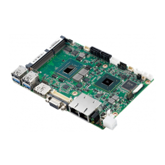
- Page 2 User Manual MIO-5290 ® Intel Core™ i7 / i3, 3.5" MI/O-Compact SBC, DDR3/DDR3L, VGA, HDMI, 48-bit LVDS, 2 x GbE, 2 x Mini PCIe, mSATA, iManager, MIOe...
- Page 3 No part of this manual may be reproduced, copied, translated or transmitted in any form or by any means without the prior written permission of Advantech Co., Ltd. Information provided in this manual is intended to be accurate and reliable. How- ever, Advantech Co., Ltd.
- Page 4 Because of Advantech’s high quality-control standards and rigorous testing, most of our customers never need to use our repair service. If an Advantech product is defec- tive, it will be repaired or replaced at no charge during the warranty period. For out- of-warranty repairs, you will be billed according to the cost of replacement materials, service time and freight.
- Page 5 Discard used batteries according to the manufacturer's instruc- tions. Technical Support and Assistance Visit the Advantech website at http://support.advantech.com where you can find the latest information about the product. Contact your distributor, sales representative, or Advantech's customer service center for technical support if you need additional assistance. Please have the following information ready before you call: –...
- Page 6 1 x COM RS-422/485 Cable 25cm (p/n: 1700019435) 1 x Cooler (MIO-5290U series only) (p/n: 1960057432N001) 1 x Cooler (MIO-5290L series only) (p/n: 1960057431N001) 1 x Startup manual (p/n: 2006529000) 1 x Mini Jumper(10pcs package) (p/n: 9689000002) ...
- Page 7 MIO-5290 User Manual...
-
Page 8: Table Of Contents
Electrical Specifications ..............5 1.2.5 Environmental ................5 Block Diagram................... 6 Board layout: dimensions................7 Figure 1.1 MIO-5290L Mechanical Drawing (Top Side) ....7 Figure 1.2 MIO-5290 Mechanical Drawing (Bottom Side) ... 7 Figure 1.3 MIO-5290U Mechanical Drawing (Coastline) ..... 8 Chapter Installation..........9 Jumpers .................... - Page 9 3.3.5 SATA Configuration ..............23 Figure 3.8 SATA Configuration..........23 3.3.6 AMT Configuration..............24 Figure 3.9 AMT Configuration ........... 24 3.3.7 PCH-FW Configuration ............... 25 Figure 3.10PCH-FW Configuration..........25 3.3.8 Intel® Anti-Theft Technology Configuration........ 26 Figure 3.11Intel® Anti-Theft Technology Configuration ..... 26 3.3.9 Intel®...
- Page 10 Jumper and Connector Tables..............52 Appendix B System Assignments ......75 System I/O Ports ..................76 Table B.1: System I/O Ports ............76 DMA Channel Assignments ..............76 Table B.2: DMA Channel Assignments........76 1st MB Memory Map ................76 Table B.3: 1st MB Memory Map ..........76 Interrupt Assignments ................
- Page 11 MIO-5290 User Manual...
-
Page 12: Chapter 1 General Information
Chapter General Information This chapter gives background information on the MIO-5290. Sections include: Introduction Specifications Block diagram Board layout and dimensions... -
Page 13: Introduction
Introduction Advantech created the stackable architecture MI/O Extension Single Board Com- puter as a SBC design with flexible and multiple I/O support (hence the name MI/O) and united extended interface connector. The new MI/O Extension Single Board Computer: MIO-5290, based on the 3 generation Intel ®... - Page 14 Chipset: Intel® QM77 I/O Controller – Direct Media Interface ∗ Up to 20 Gb/s each direction, full duplex ∗ Transparent to software – Integrated Serial ATA Host Controller ∗ Data transfer rates up to 6.0 Gb/s (600 MB/s) ∗ Integrated AHCI controller –...
-
Page 15: Os Support
– AMI 64-Mbit SPI Flash BIOS 1.2.2 OS support MIO-5290 supports Win 8, Win7, Win XP, WES7 and WES For further information about OS support of MIO-5290, please Advantech website: http://support.advantech.com.tw/ or contact the technical support center. MIO-5290 User Manual... -
Page 16: Mechanical Specifications
1.2.3 Mechanical Specifications Dimensions: 146 x 102 mm (5.7 x 4 inches) Height: Top Side: 37 mm (MIO-5290U series), 47.7 mm (MIO-5290L series); Bottom Side: 9 mm Weight: 0.84 kg (reference weight of total package) 1.2.4 Electrical Specifications ... -
Page 17: Block Diagram
Block Diagram MIO-5290 User Manual... -
Page 18: Board Layout: Dimensions
Board layout: dimensions Figure 1.1 MIO-5290L Mechanical Drawing (Top Side) Figure 1.2 MIO-5290 Mechanical Drawing (Bottom Side) MIO-5290 User Manual... -
Page 19: Figure 1.3 Mio-5290U Mechanical Drawing (Coastline)
Figure 1.3 MIO-5290U Mechanical Drawing (Coastline) MIO-5290 User Manual... -
Page 20: Chapter 2 Installation
Chapter Installation This chapter explains the setup procedures of the MIO-5290 hard- ware, including instructions on setting jumpers and connecting peripherals, switches and indica- tors. Be sure to read all safety pre- cautions before you begin the installation procedure. -
Page 21: Jumpers
Jumpers The MIO-5290 has a number of jumpers that allow you to configure your system to suit your application. The table below lists the functions of the various jumpers. Table 2.1: Jumpers Clear CMOS Auto Power On Setting LCD Power DDR3L Select COM2 Setting Connectors... -
Page 22: Locating Connectors & Block Diagram
Locating connectors & block diagram Figure 2.1 MIO-5290L Connector Locations (Top Side) Figure 2.2 MIO-5290 Connector Locations (Bottom Side) MIO-5290 User Manual... -
Page 23: Setting Jumpers
CN19 USB2.0 port GbE1 GbE2 CN23 Power LED CN20 CN22 CN21 USB3.0 port CN15 HDD LED Figure 2.3 MIO-5290U Connector Locations (Coastline) Setting Jumpers You may configure your card to match the needs of your application by setting jump- ers. A jumper is a metal bridge used to close an electric circuit. It consists of two metal pins and a small metal clip (often protected by a plastic cover) that slides over the pins to connect them. -
Page 24: Clear Cmos (J1)
2.4.1 Clear CMOS (J1) Table 2.3: Clear CMOS (JP1) Setting Function (1-2)* Normal (default) (2-3) Clear CMOS 2.4.2 Auto Power On Setting (J2) Table 2.4: Auto Power On Setting (J2) Setting Function Power Button for Power On (1-2)* Auto Power On (default) 2.4.3 LCD Power (J3) Table 2.5: LCD Power (J3) -
Page 25: Lvds Panel Power Select (J4)
2.4.4 LVDS Panel Power Select (J4) Table 2.6: LVDS Panel Power Select (J4) Setting Function (Open)* 1.5V for Std. DDR3 (default) Close 1.35V for DDR3L 2.4.5 COM2 Setting (J5) Table 2.7: COM2 Setting (J5) Setting Function (1-2)* RS232 (default) (3-4) RS485 (5-6) RS422... -
Page 26: Chapter 3 Ami Bios Setup
Chapter AMI BIOS Setup... -
Page 27: Figure 3.1 Setup Program Initial Screen
AMIBIOS has been integrated into many motherboards for over a decade. With the AMIBIOS Setup program, you can modify BIOS settings and control the various sys- tem features. This chapter describes the basic navigation of the MIO-5290 BIOS setup screens. Figure 3.1 Setup program initial screen AMI’s BIOS ROM has a built-in Setup program that allows users to modify the basic system configuration. -
Page 28: Entering Setup
Entering Setup Turn on the computer and then press <F2> or <DEL> to enter Setup menu. Main Setup When you first enter the BIOS Setup Utility, you will encounter the Main setup screen. You can always return to the Main setup screen by selecting the Main tab. There are two Main Setup options. -
Page 29: Advanced Bios Features Setup
Advanced BIOS Features Setup Select the Advanced tab from the MIO-5290 setup screen to enter the Advanced BIOS Setup screen. You can select any of the items in the left frame of the screen, such as CPU Configuration, to go to the sub menu for that item. You can display an Advanced BIOS Setup option by highlighting it using the <Arrow>... -
Page 30: Advantech Bios Update V1.3
3.3.1 Advantech BIOS Update V1.3 Figure 3.4 Advanced BIOS Update screen Advantech BIOS Update V1.3 This item allows users to update BIOS flash rom. MIO-5290 User Manual... -
Page 31: Acpi Settings
3.3.2 ACPI Settings Figure 3.5 ACPI Setting Enable ACPI Auto Configuration This item allows users to enable or disable BIOS ACPI auto configuration. Enable Hibernation This item allows users to enable or disable hibernation. ACPI Sleep State This item allows users to set the ACPI sleep state. Lock Legacy Resources This item allows users to lock legacy devices' resources. -
Page 32: Tpm Configuration
3.3.3 TPM Configuration Figure 3.6 TPM Configuration TPM Support Disable/Enable TPM if available. MIO-5290 User Manual... -
Page 33: Cpu Configuration
3.3.4 CPU Configuration Figure 3.7 CPU Configuration Setting Hyper Threading Technology This item allows users to enable or disable Intel? Hyper Threading technology. Active Processor Cores This item allows users to set how many processor cores should be active. Limit CPUID Maximum This item allows users to limit the maximum value of CPUID. -
Page 34: Sata Configuration
3.3.5 SATA Configuration Figure 3.8 SATA Configuration SATA Controller(s) This item allows users to enable or disable the SATA controller(s). SATA Mode Selection This item allows users to select mode of SATA controller(s). MIO-5290 User Manual... -
Page 35: Amt Configuration
3.3.6 AMT Configuration Figure 3.9 AMT Configuration Intel AMT This item allows users to enable or disable Intel AMT BIOS extension. BIOS Hotkey Pressed This item allows users to enable or disable BIOS hotkey press. MEBx Selection Screen This item allows users to enable or disable MEBx selection screen. Hide Un-Configuration ME Confirmation This item allows users to hide un-configure ME without password confirmation prompt. -
Page 36: Pch-Fw Configuration
PET Progress This item allows users to enable or disable PET events progress to receive PET events or not. AMT CIRA Timeout OEM defined timeout for MPS connection to be established. WatchDog This item allows users to enable or disable WatchDog Timer. OS Timer Set OS watchdog timer. -
Page 37: Intel® Anti-Theft Technology Configuration
3.3.8 Intel® Anti-Theft Technology Configuration Figure 3.11 Intel® Anti-Theft Technology Configuration Intel® Anti-Theft Technology This item allows users to enable or disable Intel® Anti-Theft Technology function. Intel® Anti-Theft Technology Rec This item allows users to set number of times recovery. MIO-5290 User Manual... -
Page 38: Intel® Rapid Start Technology
3.3.9 Intel® Rapid Start Technology Figure 3.12 Intel® Rapid Technology Intel® Rapid Start Technology This item allows users to enable or disable Rapid Start Technology, if supported. MIO-5290 User Manual... -
Page 39: Intel Txt(Lt) Configuration
3.3.10 Intel TXT(LT) Configuration Figure 3.13 Intel TXT(LT) Configuration Secure Mode Extensions (SMX) This item allows users to enable or disable SMX. Intel TXT(LT) Support This item allows users to enable or disable Intel TXT. MIO-5290 User Manual... -
Page 40: Usb Configuration
3.3.11 USB Configuration Figure 3.14 USB Configuration Legacy USB Support Enable the support for legacy USB. Auto option disables legacy support if no USB devices are connected. USB3.0 Support This item allows users to enable or disable USB3.0 support. XHCI Hand-Off This is a workaround for the OS without XHCI hand-off support. -
Page 41: Smart Settings
3.3.12 SMART Settings Figure 3.15 SMART Settings SMART Self Test This item allows users to enable or disable SMART Self Test. MIO-5290 User Manual... -
Page 42: Embedded Controller Configuration
3.3.13 Embedded Controller Configuration Figure 3.16 Embedded Controller Configuration EC iManager WatchDog IRQ This item allows users to set the IRQ number of EC watchdog. EC Power Saving Mode This item allows users to set board's power saving mode when off. EC iManager Smart FAN This item allows users to enable or disable EC iManager smart FAN feature. -
Page 43: Super Io Configuration
3.3.14 Super IO Configuration Figure 3.17 Super IO Configuration Serial Port 0 Configuration This item allows users to configure serial port 0. Serial Port 1 Configuration This item allows users to configure serial port 1. MIO-5290 User Manual... -
Page 44: Platform Misc Configuration
3.3.15 Platform Misc Configuration Figure 3.18 Platform Misc Configuration Native PCIE Enable This item allows users to enable or disable native PCIE support feature. MIO-5290 User Manual... -
Page 45: Intel® Smart Connect Technology
3.3.16 Intel® Smart Connect Technology Figure 3.19 Intel® Smart Connect Technology ISCT Configuration This item allows users to enable or disable ISCT Configuration. MIO-5290 User Manual... -
Page 46: Serial Port Console Redirection
3.3.17 Serial Port Console Redirection Figure 3.20 Serial Port Console Redirection Console Redirection This item allows users to enable or disable console redirection for Microsoft Windows Emergency Management Services (EMS). Console Redirection This item allows users to configuration console redirection detail settings. MIO-5290 User Manual... -
Page 47: Cpu Ppm Configuration
3.3.18 CPU PPM Configuration Figure 3.21 CPU PPM Configuration EIST CPU runs at its default speed if disabled; CPU speed is controlled by the operating system if enabled. Turbo Mode This item allows users to enable or disable turbo mode. CPU C3/C6/C7 Report This item allows users to enable or disable CPU C-state support. -
Page 48: Switchable Graphics
3.3.19 Switchable Graphics Figure 3.22 Switchable Graphics SG Mode Select This item allows users to select switchable graphics mode. MIO-5290 User Manual... -
Page 49: Chipset
Chipset Select the Chipset tab from the MIO-5290 setup screen to enter the Chipset BIOS Setup screen. You can display a Chipset BIOS Setup option by highlighting it using the <Arrow> keys. All Plug and Play BIOS Setup options are described in this sec- tion. -
Page 50: System Agent (Sa) Configuration
3.4.1 System Agent (SA) Configuration Figure 3.24 System Agent (SA) Configuration VT-d This item allows users to enable or disable VT-d. DDR Selection This item allows users to select which DDR or DDRL voltage. MIO-5290 User Manual... -
Page 51: Figure 3.25Intel Igfx Configuration
3.4.1.1 Intel IGFX Configuration Figure 3.25 Intel IGFX Configuration Primary Display This item allows users to select Primary Display. Internal Graphics This item allows users to enable or disable IGD. GTT Size This item allows users to select GTT size. Aperture Size This item allows users to select aperture size. -
Page 52: Figure 3.26Lcd Control
LCD Control Figure 3.26 LCD Control Primary IGFX Boot Display Select boot display device at post stage. LCD Panel Type This item allows users to select panel resolution. Panel Scaling This item allows users to enable or disable panel scaling. Active LFP This item allows users to select LFP configuration. -
Page 53: Figure 3.27Nb Pcie Configuration
3.4.1.2 NB PCIe Configuration Figure 3.27 NB PCIe Configuration PEG0 – Gen x Select PEG0 Gen speed. Enable PEG This item allows users to enable or disable PEG always. PEG Sampler Calibrate This item allows users to enable or disable PEG sampler calibrate. Swing Control This item allows users to perform PEG swing control. -
Page 54: Pch-Io Configuration
3.4.2 PCH-IO Configuration Figure 3.28 PCH-IO Configuration PCI Express Configuration This item allows users to configuration PCIE1~PCIE8 root port detail settings. USB Configuration This item allows users to configuration detail of USB functions. PCH Azalia Configuration This item allows users to configuration detail of azalia functions. PCH LAN controller Enables or disables the PCH LAN controller. -
Page 55: Boot Settings
Boot Settings Figure 3.29 Boot Setup Utility Setup Prompt Timeout This item allows users to select the number of seconds to wait for setup activation key. Bootup NumLock State Select the Power-on state for Numlock. Quiet Boot If this option is set to Disabled, the BIOS displays normal POST messages. If Enabled, an OEM Logo is shown instead of POST messages. -
Page 56: Security Setup
Security Setup Figure 3.30 Password Configuration Select Security Setup from the MIO-5290 Setup main BIOS setup menu. All Security Setup options, such as password protection and virus protection are described in this section. To access the sub menu for the following items, select the item and press <Enter>: Change Administrator / User Password: Select this option and press <ENTER>... -
Page 57: Save & Exit
Save & Exit Figure 3.31 Save & Exit 3.7.1 Save Changes and Exit When users have completed system configuration, select this option to save changes, exit BIOS setup menu and reboot the computer if necessary to take effect all system configuration parameters. 3.7.2 Discard Changes and Exit Select this option to quit Setup without making any permanent changes to the system... -
Page 58: Restore Defaults
3.7.6 Restore Defaults The MIO-5290 automatically configures all setup items to optimal settings when users select this option. Optimal Defaults are designed for maximum system perfor- mance, but may not work best for all computer applications. In particular, do not use the Optimal Defaults if the user's computer is experiencing system configuration problems. - Page 59 MIO-5290 User Manual...
-
Page 60: Mioe Installation
Chapter MIOe Installation... -
Page 61: Quick Installation Guide
The MI/O compact form factor SBC is a new-generation SBC design with a variety of mechanical improvements. Here is the quick installation guide for our thermal design and MIOe module installation. Quick Installation Guide: There is a Heatsink / Cooler in the white box inside the package. Carefully remove the release paper from the thermal pad before installation. -
Page 62: Appendix A Pin Assignments
Appendix Pin Assignments This appendix contains informa- tion of a detailed or specialized nature. Sections include: Jumper and Connector Tables... -
Page 63: Jumper And Connector Tables
Jumper and Connector Tables Clear CMOS 1653003101 Part Number HD_3x1P_79_D Footprint PIN HEADER 3*1P 180D(M) 2.0mm DIP SQUARE W/O Pb Description Setting Function (1-2)* Normal (2-3) Clear COMS Auto Power On Setting 1653002101 Part Number HD_2x1P_79_D Footprint PIN HEADER 2*1P 180D(M)SQUARE 2.0mm DIP W/O Pb Description Setting Function... - Page 64 Power Switch 1655302020 Part Number WF_2P_79_BOX_R1_D Footprint WAFER BOX 2P 180D(M) 2.0mm W/Lock Description Pin Name PSIN Reset 1655302020 Part Number WF_2P_79_BOX_R1_D Footprint WAFER BOX 2P 180D(M) 2.0mm W/Lock Description Pin Name RESET# Inverter Power Output Part Number 1655000453 Footprint WHL5V-2M-24W1140 WAFER BOX 2.0mm 5P 180D(M) DIP WO/Pb JIH VEI Description...
- Page 65 SMBus 1655904020 Part Number FPC4V-125M Footprint Wafer SMT 1.25mmS/T type 4P 180D(M) 85205-04001 Description Pin Name SMB_DAT SMB_CLK RS422/485 1655004032 Part Number WF_5P_49_BOX_85205 Footprint Description Pin Name 422RX- 422RX+ 422/485TX+ 422/485TX- MIO-5290 User Manual...
- Page 66 SATA Power 1655001154 Part Number WF_4P_98_BOX_R1_D Footprint Description Pin Name +12V SATA2 Part Number 1654007578 Footprint SATA_7P_WATF-07DBN6SB1U Description Pin Name MIO-5290 User Manual...
- Page 67 SATA1 Part Number 1654007578 Footprint SATA_7P_WATF-07DBN6SB1U Description Pin Name Audio Part Number 1653004099 Footprint HD_5x2P_79_23N685B-10M10 Description Pin Name LOUTR LINR LOUTL LINL MIC1R MIC1L Matching Cable: 1703100152 MIO-5290 User Manual...
- Page 68 CN12 SODIMMDDR3_204 1651001649 Part Number DDR3_204P_2-2013310-1 Footprint Description Pin Name CN13 Internal USB 1653005260 Part Number HD_5x2P_79_N10 Footprint PIN HEADER 2*5P 180D(M) 2.0mm SMD IDIOT-PROOF Description Pin Name A_D- B_D- A_D+ B_D+ Matching Cable: 1703100260 1703100121 CN14 48 bits LVDS Panel 1653920200 Part Number SPH20X2...
- Page 69 LVDS0_D1- LVDS1_D1- LVDS0_D1+ LVDS1_D1+ LVDS0_D2- LVDS1_D2- LVDS0_D2+ LVDS1_D2+ LVDS0_CLK- LVDS1_CLK- LVDS0_CLK+ LVDS1_CLK+ LVDS0_D3- LVDS1_D3- LVDS0_D3+ LVDS1_D3+ MIO-5290 User Manual...
- Page 70 CN15 LAN1/LAN2 1652003274 Part Number RJ45_28P_RTB-19GB9J1A Footprint PHONE JACK RJ45 28P DIP Gold flash RTB-19GB9J1A Description Pin Name TX+(10/100),BI_DA+(GHz) TX-(10/100),BI_DA-(GHz) RX+(10/100),BI_DB+(GHz) BI_DC+(GHz) BI_DC-(GHz) RX-(10/100),BI_DB-(GHz) BI_DD+(GHz) BI_DD-(GHz) LAN1 LAN2 CN18 12V Power Input 1655404090 Part Number WF_2x2P_165_BOX_RA_D_740SP Footprint Description ATX PWR CONN. 2*2P 180D 4.2mm 24W4310-04S10-01T Pin Name +12V +12V...
- Page 71 CN19 External USB2.0+USB3.0 1654010199 Part Number USB_13P_UEA1112C-UHS6-4F Footprint Description Pin Name SSRX- SSRX+ SSTX- SSTX+ MIO-5290 User Manual...
- Page 72 CN20 External USB2.0+USB3.0 Part Number 1654010199 Footprint USB_13P_UEA1112C-UHS6-4F Description Pin Name SSRX- SSRX+ SSTX- SSTX+ MIO-5290 User Manual...
- Page 73 CN21 HDMI+DISPLAY_21H 1654010203 Part Number HDMICON_21P_845-002-217CRL Footprint Description Pin Name CN22 DC JACK 1652005624 Part Number Footprint PJ_2P_2DC-G213B200 Description Pin Name +VIN MIO-5290 User Manual...
- Page 74 CN23 1654000055 Part Number DBVGA-VF5MS Footprint D-SUB Conn. 15P 90D(F) DIP 070242FR015S200ZU Description Pin Name GREEN BLUE DDAT HSYNC VSYNC DCLK MIO-5290 User Manual...
- Page 75 CN24 COM1/COM2 1653004793 Part Number HD_10x2P_79_23N685B-20M10 Footprint Description Pin Name DCD1# DSR1# RXD1 RTS1# TXD1 CTS1# DTR1# RI1# DCD2# DSR2# RXD2 RTS2# TXD2 CTS2# DTR2# RI2# Matching Cable: 1701200220 MIO-5290 User Manual...
- Page 76 CN25 GPIO 1653004099 Part Number HD_5x2P_79_23N685B-10M10 Footprint Description Pin Name GPIO4 GPIO0 GPIO5 GPIO1 GPIO6 GPIO2 GPIO7 GPIO3 CN26 BIOS Socket Part Number 1651000682 Footprint SOCKET_8P_ACA-SPI-004-K01 Description IC SKT 8P SMD WO/Pb C ACA-SPI-004-K01 Pin Name HOLD# +3.3V MIO-5290 User Manual...
- Page 77 CN27 MIOe 1654006235 Part Number BB_40x2P_32_1625x285_2HOLD Footprint Description Pin Name PCIE_RX0+ PCIE_TX0+ PCIE_RX0- PCIE_TX0- PCIE_RX1+ PCIE_TX1+ PCIE_RX1- PCIE_TX1- PCIE_RX2+ PCIE_TX2+ PCIE_RX2- PCIE_TX2- PCIE_RX3+ PCIE_TX3+ PCIE_RX3- PCIE_TX3- PCIE_CLK+ LOUTL PCIE_CLK- LOUTR AGND SMB_CLK SMB_DAT PCIE_WAKE# RESET# SLP_S3# CLK33M MIO-5290 User Manual...
- Page 78 LPC_AD0 DDP_HPD LPC_AD1 LPC_AD2 DDP_AUX+ LPC_AD3 DDP_AUX- LPC_DRQ#0 LPC_SERIRQ DDP_D0+ LPC_FRAME# DDP_D0- USB0_D+ DDP_D1+ USB0_D- DDP_D1- USB1_D+/USB_SSTX+ DDP_D2+ USB1_D-/USB_SSTX- DDP_D2- USB2_D+/USB_SSRX+ DDP_D3+ USB2_D-/USB_SSRX- DDP_D3- USB_OC# +12VSB +12VSB +5VSB +5VSB +5VSB +5VSB MIO-5290 User Manual...
- Page 79 MIO-5290 User Manual...
- Page 80 CN28 Mini PCIE 1654006715 Part Number MINIPCIE_FULL_HALF_STANDARD Footprint Description Pin Name WAKE# +3.3VSB +1.5V UIM_PWR UIM_DATA REFCLK- UIM_CLK REFCLK+ UIM_RESET UIM_VPP PERST# PERn0 +3.3VSB PERp0 +1.5V SMB_CLK PETn0 SMB_DAT PETp0 USB D- USB D+ +3.3VSB +3.3VSB MIO-5290 User Manual...
- Page 81 +1.5V +3.3VSB MIO-5290 User Manual...
- Page 82 CN29 Mini PCIE 1654006715 Part Number MINIPCIE_FULL_HALF_STANDARD Footprint Description Pin Name WAKE# +3.3VSB +1.5V UIM_PWR UIM_DATA REFCLK- UIM_CLK REFCLK+ UIM_RESET UIM_VPP PERST# PERn0 +3.3VSB PERp0 +1.5V SMB_CLK PETn0 SMB_DAT PETp0 USB D- USB D+ +3.3VSB +3.3VSB MIO-5290 User Manual...
- Page 83 +1.5V +3.3VSB MIO-5290 User Manual...
- Page 84 FAN1 CPU FAN 1655003010 Part Number WHP3VA Footprint Description Pin Name +V12 FANTACH FAN2 System FAN 1655003010 Part Number WHP3VA Footprint Description Pin Name +V12 MIO-5290 User Manual...
- Page 85 MIO-5290 User Manual...
-
Page 86: Appendix B System Assignments
Appendix System Assignments This appendix contains informa- tion of a detailed nature. Sections include: System I/O Ports DMA Channel Assignments 1st MB Memory Map Interrupt Assignments... -
Page 87: System I/O Ports
System I/O Ports Table B.1: System I/O Ports Addr. Range (Hex) Device 00-1F DMA Controller 20-2D Interrupt Controller 50-52 Timer/Counter 60-6F 8042 (keyboard controller) 70-7F Real-time clock, non-maskable interrupt (NMI) mask 80-9F DMA page register A0-BF 0A0-0BF C0-DF DMA controller 200-20F Motherboard resources 299-29A... -
Page 88: Interrupt Assignments
Interrupt Assignments Table B.4: Interrupt Assignments Interrupt# Interrupt source Parity error detected IRQ0 System timer IRQ1 Standard 101/102-Key or Microsoft Natural PS/2 Keyboard IRQ2 Interrupt from controller 2 (cascade) IRQ3 Communications Port (COM2) IRQ4 Communications Port (COM1) IRQ5 Available IRQ6 Available IRQ7 EC Watch DOG... - Page 89 MIO-5290 User Manual...
-
Page 90: Appendix C Watchdog Timer Sample Code
Appendix Watchdog Timer Sample Code... -
Page 91: Watchdog Timer Sample Code
Watchdog Timer Sample Code EC_Command_Port = 0x29Ah EC_Data_Port = 0x299h Write EC HW ram = 0x89 Watch dog event flag = 0x57 Watchdog reset delay time = 0x5E Reset event = 0x04 Start WDT function = 0x28 ==================================================== .model small .486p .stack 256 .data... - Page 92 Appendix C Watchdog Timer Sample Code...
- Page 93 No part of this publication may be reproduced in any form or by any means, electronic, photocopying, recording or otherwise, without prior written permis- sion of the publisher. All brand and product names are trademarks or registered trademarks of their respective companies. © Advantech Co., Ltd. 2013...
- Page 94 Our company network supports you worldwide with offices in Germany, Austria, Switzerland, Great Britain and the USA. For more information please contact: FORTEC Elektronik AG FORTEC Elektronik AG Hauptniederlassung Büro West Lechwiesenstr. 9 Hohenstaufenring 55 86899 Landsberg am Lech 50674 Köln Telefon: +49 (0) 8191 91172-0 Telefon:...
Need help?
Do you have a question about the MIO-5290L and is the answer not in the manual?
Questions and answers