Table of Contents
Advertisement
Quick Links
Advertisement
Table of Contents

Related Manuals for Advantech MIO-5377R


Summary of Contents for Advantech MIO-5377R
- Page 2 Manual Advantech MIO-5377R 3.5" SBC 13th Gen. Intel® Core™ Processors Raptor Lake-P The information contained in this document has been carefully researched and is, to the best of our knowledge, accurate. However, we assume no liability for any product failures or damages, immediate or consequential, resulting from the use of the information provided herein.
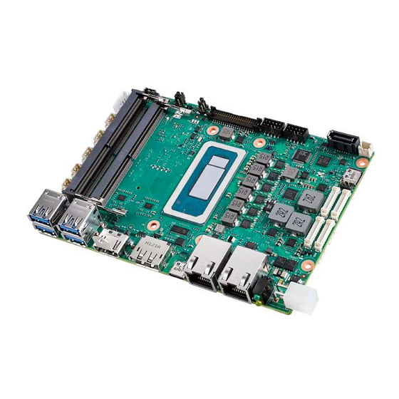
- Page 3 User Manual MIO-5377 ® 13th/12th Gen Intel Core™ P/U Series Processors (i7/i5/i3/ U300E) 3.5" MI/O Compact SBC...
- Page 4 No part of this manual may be reproduced, copied, translated, or transmitted in any form or by any means without the prior written permission of Advantech Co., Ltd. Information provided in this manual is intended to be accurate and reliable. How- ever, Advantech Co., Ltd.
- Page 5 Because of Advantech’s high quality-control standards and rigorous testing, most of our customers never need to use our repair service. If an Advantech product is defec- tive, it will be repaired or replaced at no charge during the warranty period. For out- of-warranty repairs, you will be billed according to the cost of replacement materials, service time and freight.
- Page 6 Class I, Division 2, Groups A, B, C, and D indoor hazards. Technical Support and Assistance Visit the Advantech website at http://support.advantech.com where you can find the latest information about the product. Contact your distributor, sales representative, or Advantech's customer service center for technical support if you need additional assistance.
- Page 7 Packing List Before setting up the system, check that the items listed below are included and in good condition. If any item does not accord with the table, please contact your dealer immediately. 1 x MIO-5377 SBC 1 x SATA Cable 30 cm (P/N: 1700006291) ...
- Page 8 MIO-5377 User Manual...
-
Page 9: Table Of Contents
Contents Chapter General Information ......1 Introduction ....................2 Specifications .................... 2 Block Diagram................... 5 Chapter Mechanical Specifications....7 Introduction ....................8 Board Layout: Dimensions ................ 8 Figure 2.1 MIO-5377 Mechanical Diagram (Top Side) ....8 Figure 2.2 MIO-5377 Mechanical Diagram (Bottom Side) ... 8 Figure 2.3 MIO-5377 Mechanical Diagram (Coastline) .... - Page 10 Entering Setup ..................32 4.1.1 Main Setup.................. 32 4.1.2 Advanced BIOS Features Setup..........33 4.1.3 Chipset Configuration ..............54 4.1.4 Security..................64 4.1.5 Boot .................... 65 4.1.6 Save & Exit ................. 66 Appendix A ............67 System I/O Ports..................68 DMA Channel Assignments ..............
-
Page 11: Chapter 1 General Information
Chapter General Information... -
Page 12: Introduction
MIO-5377 is powered by 13th/12th Gen Intel Core™ P/U series processors and offers Advantech embedded software APIs, such as iManager 3.0, SUSI 4.0, and DeviceOn, which were created by Advantech to monitor and control system opera- tion effectively and remotely. Advantech has also validated MIO-5377 with the embedded OS: Windows 10 LTSC and Ubuntu v22.04 LTS, ready for bundled ship-... - Page 13 Serial Bus 3 x I2C (CN6 is a BOM option for 1 x SMBus by request; First priority is to use CN6; On Windows, CN7 & CN8 are supported by custom BIOS) Audio Realtek ALC888s, Line-in/Line-out/MIC GPIO 8-bit general purpose input output I/O Inverter 12V/5V/3.3V selectable 12V, 1A (4-wire)
- Page 14 External I/O Ethernet 2 x RJ-45 HDMI/DP 1 x HDMI, 1 x DP USB Type-C 1 x USB 3.2 Gen.2 x 1 10Gbps, support DisplayPort 1.4 Alt. Mode USB Type-A 4 x USB 3.2 Gen2. x 1 10Gbps Power status, SATA R/W Power DC-Jack Optional Internal I/O SATA 1 x SATA Gen.3 6.0Gbps...
-
Page 15: Block Diagram
Block Diagram MIO-5377 User Manual... - Page 16 MIO-5377 User Manual...
-
Page 17: Chapter 2 Mechanical Specifications
Chapter Mechanical Specifications... -
Page 18: Introduction
Introduction MI/O is a compact form factor, new-generation SBC designed with a variety of mechanical improvements. This chapter includes board dimensions and assembly instructions for standard thermal solutions. Board Layout: Dimensions 98.70 92.70 88.20 55.65 27.20 23.09 20.50 Figure 2.1 MIO-5377 Mechanical Diagram (Top Side) 98.70 92.70 27.20... - Page 19 16.34 11.20 Figure 2.3 MIO-5377 Mechanical Diagram (Coastline) 33.7 16.34 11.20 Figure 2.4 MIO-5377 Mechanical Diagram (with Heatsink) 16.34 11.20 Figure 2.5 MIO-5377 Mechanical Diagram (with Cooler) 16.19 2.25 10.75 Figure 2.6 MIO-5377 Mechanical Diagram (with Heatspreader) MIO-5377 User Manual...
-
Page 20: Quick Installation Guide
Quick Installation Guide This section introduces the installation of the heatsink which can be found inside a white box inside the package. Please assemble it by following the diagram below. Remember to remove the plastic from the thermal pad before assembly. Remove release paper Figure 2.7 MIO-5377 Cooler Installation Remove release paper... -
Page 21: Chapter 3 Jumpers And Connectors
Chapter Jumpers and Connectors... -
Page 22: Jumpers
Jumpers Table 3.1: Panel Voltage Selection Jumper: VDD1 Jumper Short Panel Voltage +3.3V (Default) +12V Table 3.2: AT Mode /Load BIOS Default: J1 Jumper Short Panel Function AT/ ATX MODE Selection 1-2 open: ATX mode 1-2 short: AT mode* NORMAL_BIOS (Default) 3-4 open: Reserve 3-4 short: Reserve* LOAD_BIOS_Default:... -
Page 23: Connectors
Connectors CN10 DC Power Input Connector (90D) *CN10_1 DC Power Input Connector (180D) *CN11 DC Jack Power & SATA LED LAN1 I219 RJ-45 LAN Ports LAN2 I226 RJ-45 LAN Ports TYPEC1 Type-C Port (USB 3.2 / DP) DisplayPort Connector HDMI1 HDMI Connector USB1 USB 3.2 Connector... -
Page 24: Locating Connectors
Locating Connectors MIO-5377 User Manual... -
Page 25: Setting Jumpers
Setting Jumpers You may configure your card to match the needs of your application by setting jump- ers. A jumper is a metal bridge used to close an electric circuit. It consists of two metal pins and a small metal clip (often protected by a plastic cover) that slides over the pins to connect them. - Page 26 Table 3.5: I2C Internal Connector: CN8 1655904020 Vendor / MPN Aces / 85205-04001 Signal Pin Definition SOC_I2C1_z_DAT SOC_I2C1_z_CLK +V33_I2CCONN1 Table 3.6: I2C Internal Connector: CN7 1655904020 Vendor / MPN Aces / 85205-04001 Signal Pin Definition SOC_I2C0_z_DAT SOC_I2C0_z_CLK +V33_I2CCONN0 Table 3.7: I2C Internal Connector: CN6 1655904020 Vendor / MPN Aces / 85205-04001...
- Page 27 Table 3.8: Panel Inverter Connector: BL1 1653007388-01 Vendor / MPN Pinrex / 721-81-05TWR0 Signal Pin Definition +V12_1_INVERTER_0 LVDS1_z_ENABKL EC_LVDS1_z_PWM +V5_1_INVERTER_0 Table 3.9: Smart FAN Internal Connector: FAN 1653008788-01 Vendor / MPN Aces / 50273-00401-001 Signal Pin Definition +V12 FAN_SPEED FAN_V5_PWM MIO-5377 User Manual...
- Page 28 Table 3.10: LVDS Connector: LVDS1 1653008443-01 Vendor / MPN Hirose / DF13E-40DP-1.25V(52) Signal Pin Definition +V_LCD +V_LCD +V_LCD +V_LCD LVDS1_0_D0- LVDS1_1_D0- LVDS1_0_D0+ LVDS1_1_D0+ LVDS1_0_D1- LVDS1_1_D1- LVDS1_0_D1+ LVDS1_1_D1+ LVDS1_0_D2- LVDS1_1_D2- LVDS1_0_D2+ LVDS1_1_D2+ LVDS1_0_CLK- LVDS1_1_CLK- LVDS1_0_CLK+ LVDS1_1_CLK+ LVDS0_DDCCLK_AUX+ LVDS0_DDCCLK_AUX- LVDS1_0_D3- LVDS1_1_D3- LVDS1_0_D3+ LVDS1_1_D3+ LVDS1_VCON MIO-5377 User Manual...
- Page 29 Table 3.10: LVDS Connector: LVDS1 Table 3.11: USB 2.0 Dual-Port Internal Connector: USB 3 1653008214-01 Vendor / MPN Pinrex / 52C-90-10GBE0 Signal Pin Definition +V5SB_USB_UTC +V5SB_USB_UTC USB8_z_P- USB9_z_P- USB8_z_P+ USB9_z_P+ Table 3.12: Audio Internal Connector: AUDIO1 1653008214-01 Vendor / MPN Pinrex / 52C-90-10GBE0 Signal Pin Definition LOUTR...
- Page 30 Table 3.13: SATA Power Connector: SATA_P1 1653007538-01 Vendor / MPN Pinrex / 721-81-02TW00 Signal Pin Definition +V5SATA0 Table 3.14: COM-Port Internal Connector 1: COM1 1653007728-02 Vendor / MPN Aces / 50273-0107N-002 Signal Pin Definition COM1_RI# COM1_DTR# COM1_CTS# COM1_TXD COM1_RTS# COM1_RXD COM1_DSR# COM1_DCD# MIO-5377 User Manual...
- Page 31 Table 3.15: COM-Port Internal Connector 2: COM2 1653007728-02 Vendor / MPN Aces / 50273-0107N-002 Signal Pin Definition COM2_RI# COM2_DTR# COM2_CTS# COM2_TXD COM2_RTS# COM2_RXD COM2_DSR# COM2_DCD# Table 3.16: COM-Port Internal Connector 3: COM3 1655004032 Vendor / MPN Aces / 85205-05701 Signal Pin Definition COM3_TXD COM3_RTS# COM3_RXD...
- Page 32 Table 3.17: COM Port Internal Connector 4: COM4 1655004032 Vendor / MPN Aces / 85205-05701 Signal Pin Definition COM4_TXD COM4_RTS# COM4_RXD COM4_CTS# Table 3.18: Front Panel Internal Connector: CN4 1653007728-02 Vendor / MPN Aces / 50273-0107N-002 Signal Pin Definition BUZZER- BUZZER+ RDC_CASEOPEN SATA_HDD_LED#...
- Page 33 Table 3.19: GPIO Internal Connector: CN5 1653007728-02 Vendor / MPN Aces / 50273-0107N-002 Signal Pin Definition EC_P1_GPIO7 EC_P1_GPIO2 EC_P1_GPIO6 EC_P1_GPIO1 EC_P1_GPIO5 EC_P1_GPIO0 EC_P1_GPIO4 +V5_P1_GPIO EC_P1_GPIO3 Table 3.20: RTC battery Connector: BAT1 Signal Pin Definition +VBAT_a1 MIO-5377 User Manual...
- Page 34 Table 3.21: M.2 E-Key Connector: M2_1 Signal Pin Definition +V3.3SB_M.2_E USB6_z_P+ +V3.3SB_M.2_E USB6_z_P- MIO-5377 User Manual...
- Page 35 Table 3.21: M.2 E-Key Connector: M2_1 PCIE_M2_z_TX7+ PCIE_M2_z_TX7- PCIE_M2_RX11+ PCIE_M2_RX11- CLK_M2E_z_PCIE+ CLK_M2E_z_PCIE- SUSCLK_z_EKEY PLTRST_BUFFER# PCIE_a_CLKREQ2# BT_DISABLE# PCIE_WAKE# WIFI_DISABLE# +V3.3SB_M.2_E +V3.3SB_M.2_E MIO-5377 User Manual...
- Page 36 Table 3.21: M.2 E-Key Connector: M2_1 Table 3.22: M.2 M-Key Connector: M2_2 Signal Pin Definition +V3.3_M.2 +V3.3_M.2 PCIE4_KEY-M_RX3- PCIE4_KEY-M_RX3+ M.2_PLN# PCIE4_KEY-M_a_TX3- +V3.3_M.2 PCIE4_KEY-M_a_TX3+ +V3.3_M.2 +V3.3_M.2 PCIE4_KEY-M_RX2- +V3.3_M.2 PCIE4_KEY-M_RX2+ MIO-5377 User Manual...
- Page 37 Table 3.22: M.2 M-Key Connector: M2_2 PCIE4_KEY-M_a_TX2- PCIE4_KEY-M_a_TX2+ PCIE4_KEY-M_RX1- PCIE4_KEY-M_RX1+ PCIE4_KEY-M_a_TX1- PCIE4_KEY-M_a_TX1+ PCIE4_KEY-M_RX0- PCIE4_KEY-M_RX0+ PCIE4_KEY-M_a_TX0- PCIE4_KEY-M_a_TX0+ PLTRST_MKEY_BUFFER# CLK2_M2MB_a_PCIE_REQ# CK_100M_a_MKEY_N M.2_PCIE_WAKE# CK_100M_a_MKEY_P PCH_SUSCLK_R_MKEY +V3.3_M.2 +V3.3_M.2 +V3.3_M.2 MIO-5377 User Manual...
- Page 38 Table 3.22: M.2 M-Key Connector: M2_2 Table 3.23: M.2 B-Key Connector: M2_B1 Signal Pin Definition M2B1_CFG3 +V3.3A_M.2_B +V3.3A_M.2_B M2B1_FULL_CARD_OFF# USB_M2B1_P M2B1_W_DISABLE1# USB_M2B1_N M2B1_LED1# M2B1_PCIE_DIS M2B1_CFG0 M2B1_ANT_CFG M2B1_WAKE_ON_WWAN# M2B1_ANT_TUNER M2B1_DPR M2B1_W_DISABLE2# MIO-5377 User Manual...
- Page 39 Table 3.23: M.2 B-Key Connector: M2_B1 M2B1_UIM_RESET M2B1_UIM_CLK M2B1_UIM_DATA M2B1_UIM_PWR M2B1_PCIE_RX- M2B1_PCIE_RX+ M2B1_PCIE_TX- M2B1_PCIE_TX+ M2B1_PERST# M2B1_a_CLKREQ# CLK100M_a_M2B1- M2B1_PCIEWAKE# CLK100M_a_M2B1+ M2B1_a_RESET# M2B1_SUSCLK M2_SATA1B_PEDET +V3.3A_M.2_B +V3.3A_M.2_B MIO-5377 User Manual...
- Page 40 Table 3.23: M.2 B-Key Connector: M2_B1 +V3.3A_M.2_B M2B1_CFG2 MIO-5377 User Manual...
-
Page 41: Chapter 4 Ami Bios Setup
Chapter AMI BIOS Setup... -
Page 42: Entering Setup
BIOS supports your CPU. If there is no number assigned to the patch code, please contact an Advantech application engineer to obtain an up-to-date patch code file. This will ensure that your CPU’s system status is valid. -
Page 43: Advanced Bios Features Setup
The Main BIOS setup screen has two main frames. The left frame displays all the options that can be configured. Grayed-out options cannot be configured; options in blue can. The right frame displays the key legend. Above the key legend is an area reserved for a text message. When an option is selected in the left frame, it is highlighted in white. - Page 44 4.1.2.1 RC ACPI Settings PTID Support Determines if it is Enabled to load the PTID Table. Native PCIE Enable Enable/Disable PCIE Native Control reported in the ACPI Table. Native ASPM Choose if the ASPM feature is to be controlled by the OS or BIOS. BDAT ACPI Table Support ...
- Page 45 This item Enables/Disables ACPI Low Power S0 Idle Capability under the OS. 4.1.2.2 CPU Configuration C6DRAM Enable/Disable moving DRAM contents to PRM memory when the CPU is in C6 state. CPU Flex Ratio Override Enable/Disable CPU Flex Ratio Programming. Hardware Prefetcher ...
- Page 46 Intel Trusted Execution Technology Enables utilization of additional hardware capability provided by Intel® Trusted Execution Technology. Total Memory Encryption Configure Total Memory Encryption (TME) to protect DRAM data from physical attacks. 4.1.2.3 Power & Performance CPU – Power Management Control ...
- Page 47 4.1.2.3.1CPU - Power Management Control Boot performance mode Select the performance state that the BIOS will set before OS handoff. Intel® SpeedStep™ Allows more than two frequency ranges to be supported. Intel® Speed Shift Technology Enable/Disable Intel® Speed Shift Technology support. HDC Control ...
- Page 48 View/Configure Turbo Options Turbo Ratio Limit Option View/Configure Turbo Ratio Limit Options. Energy Efficient P-state Enable/Disable Energy Efficient P-state feature. Package Power Limit MSR Lock Enable/Disable locking of Package Power Limit settings. Energy Efficient Turbo Enable/Disable the Energy Efficient Turbo feature. Config TDP Configurations MIO-5377 User Manual...
- Page 49 Enable Configurable TDP Applies TDP initialization settings based on non-cTDP or cTDP. Configurable TDP Boot Mode Configurable TDP Mode as Nominal/Up/Down/Deactivate TDP selection. Configurable TDP Lock Configurable TDP Mode Lock sets the Lock bit. CTDP BIOS control ...
- Page 50 4.1.2.3.2GT - Power Management Control RC6(Render Standby) Check to Enable render standby support. Maximum GT frequency Maximum GT frequency limited by user. Disable Turbo GT frequency Enable/Disable Turbo GT frequency. 4.1.2.4 PCH-FW Configuration ME State When Disabled ME will put ME into Temporarily Disabled Mode. MIO-5377 User Manual...
- Page 51 Manageability Feature State When Disabled, ME will not be unconfigured on RTC Clear. AMT BIOS Features When Disabled, ME will not be unconfigured on RTC Clear. AMT Configuration Configure Intel® Active Management Technology Parameters. ME Unconfig on RTC Clear ...
- Page 52 Remote Platform Erase configuration menu. 4.1.2.5 ACPI Settings Enable ACPI Auto Configuration Enable or disable BIOS ACPI auto configuration. Enable Hibernation Enables or Disables the system’s ability to Hibernate (OS/S4 Sleep State). This option may be not effective with some OS. ACPI Sleep State ...
- Page 53 4.1.2.6 iManager Configuration CPU Shutdown Temperature Enable/Disable CPU Shutdown Temperature. Power Saving Mode Enable/Disable power saving mode. Backlight Enable Polarity Switch Backlight Enable Polarity for Native or Invert. Backlight Control Mode Switch Backlight Control to PWM or DC mode. Brightness PWM Polarity ...
- Page 54 GPIO Configuration Settings. ACPI Report Method Configuration Select ACPI Reporting Method for EC Devices. 4.1.2.6.1Serial Port 1 Configuration Serial Port Enable or Disable Serial Port (COM). Change Settings Select an optimal setting for Super IO device. COM Port Mode ...
- Page 55 4.1.2.6.2Serial Port 2 Configuration Serial Port Enable or Disable Serial Port (COM). Change Settings Select an optimal setting for Super IO device. COM Port Mode COM Port Mode Select. 4.1.2.6.3Serial Port 3 Configuration Serial Port Enable or Disable Serial Port (COM). Change Settings ...
- Page 56 Select an optimal settings for Super IO device. 4.1.2.6.4Serial Port 4 Configuration Serial Port Enable or Disable Serial Port (COM). Change Settings Select an optimal setting for Super IO device. 4.1.2.6.5Hardware Monitor MIO-5377 User Manual...
- Page 57 4.1.2.6.6Watch Dog Timer Configuration Watch Dog Timer Enable or Disable the Watch Dog Timer Function. 4.1.2.6.7GPIO Configuration GPIO Control Enable Choose to control GPIO by EC or user override during the POST stage. GPIO0/1/2/3/4/5/6/7 Configure GPIO0/1/2/3/4/5/6/7. MIO-5377 User Manual...
- Page 58 4.1.2.6.8ACPI Report Method Configuration ACPI Report Method Control Select ACPI Reporting Method for EC Devices. Active High-Speed COM Port Select to Enable High-Speed COM Port or Standard COM Port. ACPI Report Method for I2C Bus Select ACPI Reporting Method for EC I2C Bus. ACPI Report Method for CAN Bus ...
- Page 59 4.1.2.7 Trusted Computing Security Device Support Enable or disable BIOS support for security device. SHA256 PCR Bank Enable or Disable SHA256 PCR Bank. Pending operation Schedule an operation for the Security Device. Platform Hierarchy Enable or Disable Platform Hierarchy. Storage Hierarchy ...
- Page 60 4.1.2.8 S5 RTC Wake Settings Wake system from S5 Enable or disable System wake on an alarm event. Select FixedTime for the system to wake on the hr:min:sec specified. 4.1.2.9 Serial Port Console Redirection Console Redirection This item allows users to configure console redirection detailed settings. Console Redirection EMS ...
- Page 61 4.1.2.10 Intel TXT Information Intel TXT Information Display Intel TXT information. 4.1.2.11 USB Configuration Legacy USB Support Enables Legacy USB support. The Auto option disables legacy support if no USB devices are connected. The Disabled option will keep USB devices avail- able only for EFI applications.
- Page 62 USB Mass Storage Driver Support Enable/Disable USB Mass Storage Driver Support. USB transfer time-out Time-out value for control, bulk, and interrupt transfers. Device reset time-out A USB mass storage device starts unit command time-out. Device power-up delay ...
- Page 63 4.1.2.13 CSM Configuration CSM Support Enable/Disable CSM Support. GateA20 Active UPON REQUEST - GA20 can be disabled using BIOS services. ALWAYS - do not allow disabling GA20; this option is useful when any RT code is executed above 1MB. INT19 Trap Response ...
-
Page 64: Chipset Configuration
4.1.2.14 NVMe Configuration 4.1.3 Chipset Configuration Select the Chipset tab from the MIO-5377 setup screen to enter the Chipset BIOS setup screen. You can display a Chipset BIOS setup option by highlighting it using the <Arrow> keys. All Plug and Play BIOS Setup options are described in this sec- tion. - Page 65 4.1.3.1 System Agent (SA) Configuration Memory Configuration Memory Configuration Parameters. Graphics Configuration Graphics Configuration Parameters. DMI/OPI Configuration Control various DMI functions. TCSS setup menu TCSS configuration settings. Display setup menu Display configuration settings. Stop Grant Configuration ...
- Page 66 4.1.3.1.1Memory Configuration Memory Test on Warm Boot Enable/Disable Base Memory Test Run on Warm Boot. Max TOLUD Maximum Value of TOLUD. SA GV System Agent Geyserville. Gear Ratio Gear ratio when SAGV is disabled. Memory Scrambler ...
- Page 67 4.1.3.1.2Graphics Configuration Graphics Turbo IMON Current Graphics turbo IMON current values supported. GTT Size Select the GTT Size. Aperture Size Select the Aperture Size. PSMI Support Enable/Disable PSMI. DVMT Pre-Allocated Select DVMT 5.0 Pre-Allocated (Fixed) Graphics Memory size used by the Internal Graphics Device.
- Page 68 4.1.3.1.3DMI/OPI Configuration DMI Gen3 Eq Phase 2 Perform Gen3 Equalization Phase 2. DMI Gen3 Eq Phase 3 Method Select Method for Gen3 Equalization Phase 3. DMI Gen3 ASPM DMI Gen3 ASPM Support. 4.1.3.1.4TCSS Setup Menu TCSS xHCI Support ...
- Page 69 Enable/Disable ITBT PCIE Root. ITBT DMA0 Enable/Disable ITBT DMA0. 4.1.3.1.5Display Setup Menu NXP Non-EDID Support Non-EDID Support. Color Depth & Data Packing Color depth and data packing format for Non-EDID support. Dual LVDS Mode Select LVDS bus to Single bus mode or Dual bus mode. LVDS Panel Type ...
- Page 70 4.1.3.2 PCH-IO Configuration PCI Express Configuration PCI Express configuration settings. SATA Configuration SATA Device options settings. USB Configuration USB configuration settings. Security Configuration Security configuration settings. HD Audio Configuration HD Audio Subsystem configuration settings. PCH LAN Controller ...
- Page 71 4.1.3.2.1PCI Express Configuration DMI Link ASPM Control This item controls Active State Power Management of the DMI Link. PCI Express Root Port 5/12 PCI Express Port 5/12 Settings. 4.1.3.2.2SATA Configuration SATA Controller(s) Enable/Disable SATA Device. SATA Mode Selection ...
- Page 72 Indicates the maximum speed the SATA controller can support. Aggressive LPM Support Enable PCH to aggressively enter link power state. 4.1.3.2.3USB Configuration USB2 PHY Sus Well Power Gating Select ‘Enabled’ to enable SUS Well PG for USB2 PHY. USB Overcurrent ...
- Page 73 4.1.3.2.4Security Configuration RTC Memory Lock Enable will lock bytes 38h-3Fh in the lower/upper 128-byte bank of RTC RAM. BIOS Lock Enable or Disable the PCH BIOS Lock Enable feature. Force unlock on all GPIO pads If Enabled BIOS will force all GPIO pads to be in the unlock state. 4.1.3.2.5HD Audio Configuration HD Audio ...
-
Page 74: Security
4.1.3.2.6Serial IO Configuration I2C0/I2C1 Controller Enable/Disable Serial IO Controller. Serial IO I2C0/I2C1 Settings Configure Serial IO Controller. Serial IO timing parameters Enable additional timing parameters for all Serial IO controllers. 4.1.4 Security Select Security Setup from the MIO-5377 setup main BIOS setup menu. All Security setup options, such as password protection and virus protection are described in this MIO-5377 User Manual... -
Page 75: Boot
section. To access the sub-menu for the following items, select the item and press <Enter>: Change Administrator / User Password Select this option and press <ENTER> to access the sub-menu, and then type in the password. Secure Boot Secure Boot Configuration. -
Page 76: Save & Exit
4.1.6 Save & Exit Save Changes and Exit This item allows you to exit system setup after saving the changes. Discard Changes and Exit This item allows you to exit system setup without saving any changes. Save Changes and Reset ... - Page 77 Appendix...
-
Page 78: System I/O Ports
System I/O Ports Addr. Range (Hex) Device 00h-1Fh DMA Controller 20h-2Dh Interrupt Controller 2Eh–2Fh Motherboard resources 30h-3Dh Interrupt Controller 40h-43h Timer/Counter 4Eh–4Fh Motherboard resources 50h-53h Timer/Counter 60h-6Fh 8042 (keyboard controller)/NMI Controller/Microcontroller 70h-7Fh Real-time Controller 80h-8Fh Debug Port/Reserved 90h-9Fh Debug Port/Reset Generator A0h-ADh Interrupt Controller B0h-B1h... -
Page 79: Dma Channel Assignments
DMA Channel Assignments Channel Function Available Available Available Available Direct memory access controller Available Available Available 1st MB Memory Map Addr. Range (Hex) Device E0000h - FFFFFh System board D0000h - DFFFFh PCI Bus C0000h - CFFFFh System board A0000h - BFFFFh PCI Bus A0000h - BFFFFh Intel®... - Page 80 No part of this publication may be reproduced in any form or by any means, such as electronically, by photocopying, recording, or otherwise, without prior written permission from the publisher. All brand and product names are trademarks or registered trademarks of their respective companies. © Advantech Co., Ltd. 2023...
- Page 81 Our company network supports you worldwide with offices in Germany, Austria, Switzerland, the UK and the USA. For more information please contact: Headquarters Germany FORTEC Elektronik AG Augsburger Str. 2b 82110 Germering Phone: +49 89 894450-0 E-Mail: info@fortecag.de Internet: www.fortecag.de Fortec Group Members Austria Distec GmbH Office Vienna...
Need help?
Do you have a question about the MIO-5377R and is the answer not in the manual?
Questions and answers