Table of Contents
Advertisement
Quick Links
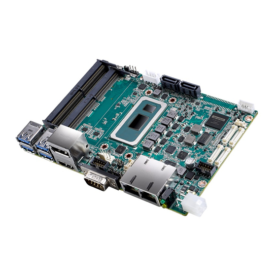
MIO-5373 3.5" MI/O-Compact SBC, 8th Gen. Intel® Core™
U-series (i7/i5/i3/Celeron®), DDR4, eMMC, HDMI, DP, 48-bit
LVDS, 2 GbE, M.2 B-key 2280, DC-in 12-24V, iManager
Startup Manual
Packing List
Before you begin installing your board, please make sure
that the following items have been shipped:
• 1 x MIO-5373 SBC
• 1 x Startup Manual (P/N: 2046537300)
• 1 x SATA Cable 30cm (P/N: 1700006291)
• 1 x SATA Power Cable 35cm (P/N: 1700018785)
• 1 x Audio JACK*3 Cable 20cm (P/N: 1700019584)
• 1 x COM RS-232 Cable 20cm (P/N: 1700030404-01)
• 1 x MIO-5373 Heatsink for 0 ~ 60°C
(P/N: 1960091427N001)
• 1 x Mini Jumper (P/N: 9689000002)
If any of these items are missing or damaged, please con-
tact your distributor or sales representative immediately.
Note1:
For detailed contents of MIO-5373, please refer
to information on the support website: http://sup-
port.advantech.com.tw/
Note2:
Adobe Reader is required to view any PDF file.
Adobe Reader can be downloaded at: http://get.
adobe.com/tw/reader/otherversions/ (Adobe is
the trademark of Adobe Systems Incorporated)
For more information on this and other Advantech
products, please visit our website at:
http://www.advantech.com
http://www.advantech.com/eplatform
For technical support and service, please visit our
support website at:
http://support.advantech.com.tw/
This manual is for MIO-5373.
Part No. 2046537300
Printed in China
Specifications
General
• CPU:
• System Memory: Dual Channel/SODIMM DDR4-2400MT/s, up
• BIOS: AMI EFI 256Mbit
• Watchdog Timer: 65536 level, 0~65535 sec
• TPM 2.0
• iManager 3.0: Yes
• Expansion Interface:
• Battery: Lithium 3V/ 210mAH
• Audio: Supports High Definition Audio (HD), line-in, line-
Display
• Controller: Intel® WHL-U SoC integrated, HDMI display
• Maximum Resolution:
• Multiple Display: Triple simultaneous displays by 48-bit
Ethernet Interface
• Speed: 10/100/1000 Mbps
• Controller: GbE1 - Intel i219, GbE2 - Intel i210-AT
• Connector: RJ45 x2
1st Edition
February 2020
- Intel® Core™ i7-8665UE (Quad-Core, 1.70GHz)
- Intel® Core™ i5-8365UE (Quad-Core, 1.60GHz)
- Intel® Core™ i3-8145UE (Dual-Core, 2.20GHz)
to 32GB
- M.2:
1 x M.2 E-key 2230
1 x M.2 B-key 2280 (SATA or NVMe PCIex2), 3042 LTE
module (support USB2.0 only), optional M-key 2280
NVMe PCIex4.
- MI/O Extension connector: 4 PCIex1, 1 PCIex4, USB2.0,
LPC, SMBus, Line-out, 12V/5V Power supply
out, Mic-in
output ALC-888S for 48-bit LVDS display output
LCD:
- LVDS Dual Channel 48-bit up to 1920 x 1200
- Option eDP1.4 up to 4096x2304@60Hz
HDMI/DP:
- 1 Port HDMI1.4 up to 4096x2160@30/24Hz
- 1 Port DP1.2 up to 4096x2306@60Hz
LVDS/eDP+HDMI+DP
MIO-5373 Startup Manual 1
Advertisement
Table of Contents

Related Manuals for Advantech MIO-5373


Summary of Contents for Advantech MIO-5373
- Page 1 • 1 x Audio JACK*3 Cable 20cm (P/N: 1700019584) • BIOS: AMI EFI 256Mbit • 1 x COM RS-232 Cable 20cm (P/N: 1700030404-01) • Watchdog Timer: 65536 level, 0~65535 sec • 1 x MIO-5373 Heatsink for 0 ~ 60°C • TPM 2.0 (P/N: 1960091427N001) • iManager 3.0: Yes • 1 x Mini Jumper (P/N: 9689000002)
- Page 2 CN30 GPIO/RS232 Connector Panel Voltage Selection CN30A1 MIOe Connector LVDS JEIDA and VESA mode Selection CN31 I2C Bus Connector Clear CMOS CN32 System FAN Connector CN35 CANBus Connector CN36 SMBus Connector CN37 DC input Connector (Adapter) 2 MIO-5373 Startup Manual...
- Page 3 Panel Voltage Setting: J2: RI# 5V/12V selection pin for CN9 +V12 Function Jumper Setting Signal Pin Definition COM(CN9) voltage setting: +V3.3 +V_CH7511B_LCD +V12 COM(CN9) voltage setting: +V12 Panel Voltage Setting: RI# (Default) Signal Pin Definition CN9_RI# COM_RI# CN9_RI# +V12 CN9_RI# MIO-5373 Startup Manual 3...
- Page 4 Discard used batteries ac- cording to manufacturer’s instructions. JEIDA mode Setting: +V3.3 VESA mode Setting: GND (Default) Signal Pin Definition LVDS1_VCON LVDS1_VCC SW1: Clear CMOS Function Jumper Setting Keep COMS Data (Default) Clear CMOS Date Signal Pin Definition RTC_a_RST# RTC_RST# 4 MIO-5373 Startup Manual...
- Page 5 CN24 CN37 CN23 CN32 CN22 CN15 CN11 CN36 CN31 J2 J3 Figure 1: MIO-5373 Connector Locations (Top Side) CN14 CN16 CN17 CN30A1 CN20 Figure 2: MIO-5373 Connector Locations (Bottom Side) Figure 3: MIO-5373 Connector Locations (Coastline) MIO-5373 Startup Manual 5...
- Page 6 Mechanical Drawing Figure 4: MIO-5373 Mechanical Drawing (Top Side) Figure 5: MIO-5373 Mechanical Drawing (Bottom Side) Figure 6: MIO-5373 Mechanical Drawing (Coastline) DESCRIPTION/PART NAME APPROVED 2019/10/3 DRAWER MODEL NAME INTERIOR 2019/10/3 DESIGNER PART APPEARANCE 2019/10/3 CHECKED PART PART NO. P/N ADDED CODE...
- Page 7 Mechanical Drawing (Cont.) Figure 7: MIO-5373 Mechanical Drawing (with Heatsink) Quick Installation Guide 1. There is a Heatsink in the white box, please take it and remove the release paper from the thermal pads. Remove Release Paper 2. There are eight screws, six studs and two nuts inside the white box, please install the heatsink into place as per illustration...
Need help?
Do you have a question about the MIO-5373 and is the answer not in the manual?
Questions and answers