Table of Contents
Advertisement
Quick Links
Advertisement
Table of Contents

Related Manuals for Advantech SOM-3569


Summary of Contents for Advantech SOM-3569
- Page 2 Manual Advantech SOM-3569 QSeven™ Computer-on-Module with Intel® Apollo Lake Atom™ x5-E3930/x5-E3940/x7-E3950, Pentium® N4200 or Celeron®Series SoC N3350 Processor The information contained in this document has been carefully researched and is, to the best of our knowledge, accurate. However, we assume no liability for any product failures or damages, immediate or consequential, resulting from the use of the information provided herein.
- Page 3 User Manual SOM-3569...
- Page 4 No part of this manual may be reproduced, copied, translated or transmitted in any form or by any means without the prior written permission of Advantech Co., Ltd. Information provided in this manual is intended to be accurate and reliable. How- ever, Advantech Co., Ltd.
- Page 5 Class I, Division 2, Groups A, B, C and D indoor hazards. Technical Support and Assistance Visit the Advantech website at http://support.advantech.com where you can find the latest information about the product. Contact your distributor, sales representative, or Advantech's customer service center for technical support if you need additional assistance.
- Page 6 Before setting up the system, check that the items listed below are included and in good condition. If any item does not accord with the table, please contact your dealer immediately. SOM-3569 CPU module 1 x Heatspreader (1960083260N001 or 1960083261N001) SOM-3569 User Manual...
- Page 7 The sound pressure level at the operator's position according to IEC 704-1:1982 is no more than 70 dB (A). DISCLAIMER: This set of instructions is given according to IEC 704-1. Advantech disclaims all responsibility for the accuracy of any statements contained herein.
- Page 8 Don't touch any components on the CPU card or other cards while the PC is on. Disconnect power before making any configuration changes. The sudden rush of power as you connect a jumper or install a card may damage sensitive elec- tronic components. SOM-3569 User Manual...
-
Page 9: Table Of Contents
Power Management..............8 1.3.10 Environment.................. 9 1.3.11 MTBF .................... 9 1.3.12 OS Support (duplicate with SW chapter) ........9 1.3.13 Advantech iManager ..............9 1.3.14 Power Consumption..............10 1.3.15 Performance ................10 1.3.16 Selection Guide w/ P/N ............... 11 1.3.17 Packing list.................. 11 1.3.18 Development Board .............. - Page 10 Figure 3.39Save & Exit............... 57 Chapter S/W Introduction & Installation..59 S/W Introduction ..................60 Driver Installation ..................60 4.2.1 Windows Driver Setup ..............60 4.2.2 Other OS..................60 Advantech iManager ................60 Appendix A Assignment......... 63 SOM-3569 User Manual viii...
- Page 11 SOM-3569 Qseven R2.1 Pin Assignment..........64 Appendix B Watchdog Timer ........67 Programming the Watchdog Timer ............68 Appendix C System Assignments ......69 System I/O Ports ..................70 Interrupt Assignments ................72 1st MB Memory Map ................73 SOM-3569 User Manual...
- Page 12 SOM-3569 User Manual...
-
Page 13: Chapter 1 General Information
Chapter General Information This chapter gives background information on the SOM-3569 CPU Computer on Module Sections include: Introduction Functional Block Diagram Product Specification... -
Page 14: Introduction
Intel 14nm process technology. SOM-3569 non-ECC memory supports LPDDR4 2400MT/s with 1.2V power design, and up to 8GB dual channel. SOM-3569 is able to support 4 PCIex1 with Gen2 tech- nology, as well as PCIe x1, x2, x4 configurations if requested. Most importantly, SOM-3569 adopts a 13.2mm heatsink passive thermal solution and supports CPU... - Page 15 Serial Presence Detect – refers to serial EEPROM on DRAMs that has DRAM Module configuration information Trusted Platform Module – chip to enhance the security features of a computer system UEFI Unified Extensible Firmware Interface Watch Dog Timer SOM-3569 User Manual...
-
Page 16: Functional Block Diagram
BOM Option USB3.0 Port 0 Intel® Atom™/Pentium®/ DPHY1.1 DPHY1.2 Celeron® Series SoC USB3.0 Port 1 MIPI-CSI2 (Optional) SATA Port 0-1 (GEN 3) SPI BUS SPI BIOS SMBus LPC BUS C/CAN bus/COM1/COM2 (TX/RX/CTS/RTX) TPM 2.0 EIO-IS200 WDT/FAN SD 3.0 SOM-3569 User Manual... -
Page 17: Product Specification
SDIO 4-bit for SD/MMC 1 (4-bit) Card SMBus I2C Bus SPI Bus CAN Bus Watchdog Trigger Power Button Power Good Reset Button LID Button Sleep Button Suspend to RAM (S3 mode) Wake Battery Low Alarm Thermal Control FAN Control SOM-3569 User Manual... -
Page 18: Processor System
PCI Express x1: Supports default 4 ports PCIe x1 compliant to PCIe Gen2 (5.0 GT/s) specification, configurable to PCIe x4 or PCIe x2 upon request. Several configurable combinations may need BIOS modifications. Please contact Advantech sales or FAE for more details. -
Page 19: I/O
SD Memory Card Specification v3.01. SD clock frequency at 25, 50, 100, and MHz. Data Rate up to 104 MB/s using 4 parallel data lines (SDR104 mode). 1.3.8.10 SDIO Supports one SDIO 3.0 interface 1.3.8.11 Trusted Execution Engine 3.0 (TXE3.0). SOM-3569 User Manual... -
Page 20: Power Management
Various wake-up events supporting allow user to apply into different scenario. Wake-on-LAN(WOL): Wake to S0 from S3/S4/S5 USB Wake: Wake to S0 from S3 PCIe Device Wake: depends on user inquiry and may need customized BIOS LPC Wake: depends on user inquiry and may need customized BIOS SOM-3569 User Manual... -
Page 21: Environment
1.3.12 OS Support (duplicate with SW chapter) The mission of Advantech Embedded Software Services is to "Enhance quality of life with Advantech platforms and Microsoft Windows embedded technology." We enable Windows Embedded software products on Advantech platforms to more effectively support the embedded computing community. -
Page 22: Power Consumption
3.3 Idle mode: DUT power management off and no running any program. 4. OS: Windows 10 Enterprise 1.3.15 Performance For reference performance or benchmark data that compare with other module, please refer to "Advantech COM Performance & Power Consumption Table". SOM-3569 User Manual... -
Page 23: Selection Guide W/ P/N
Optional Accessory 1.3.20 Pin Description Advantech provides useful checklists for schematic design and layout routing. A schematic checklist will specify details about each pin’s electrical properties and how to connect for different applications. The layout checklist will specify the layout con- strains and recommendations for trace length, impedance, and other necessary infor- mation during design and development. - Page 24 SOM-3569 User Manual...
-
Page 25: Chapter 2 Mechanical Information
Chapter Mechanical Information This chapter gives mechanical information on the SOM-3569 CPU Computer on Module Sections include: Board Information Mechanical Drawing Assembly Drawing... -
Page 26: Board Information
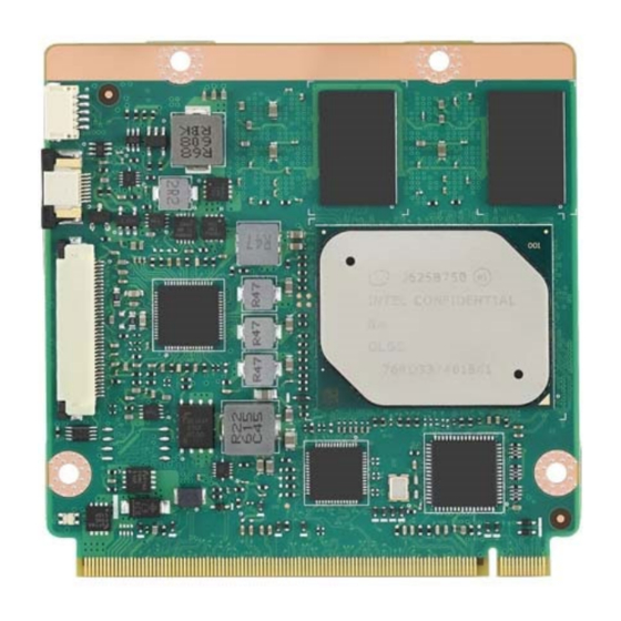
Board Information The figures below indicate the main chips on SOM-3569 Computer-on-Module. Be aware of these positions while designing a carrier board to avoid mechanical and thermal issues for the best thermal dispassion performance. LPDDR4 Onboard IC Intel® Pentium®, Celeron® and MIPI Atom®... -
Page 27: Mechanical Drawing
Mechanical Drawing For more details about 2D/3D models, please look on the Advantech COM support service website http://com.advantech.com. Figure 2.3 Board Mechanical Drawing - Front Figure 2.4 Board Mechanical Drawing - Rear SOM-3569 User Manual... - Page 28 Figure 2.5 Board Mechanical Drawing - Side SOM-3569 User Manual...
-
Page 29: Assembly Drawing
These figures demonstrate the assembly order from the thermal module and COM module to the carrier board. Figure 2.6 Assembly Drawing There are 4 reserved screw holes for SOM-3569 to be pre-assembled with the heat spreader. SOM-3569 User Manual... -
Page 30: Cpu Mechanical Drawing
Carefully consider the CPU and chip height tolerance when designing your thermal solution. Intel® Pentium and Celeron N and J Series Processors Figure 2.7 Main Chip Height and Tolerance Intel® Pentium and Celeron N and J Series Processors Figure 2.8 Main Chip Height and Tolerance SOM-3569 User Manual... -
Page 31: Chapter 3 Ami Bios
Chapter AMI BIOS This chapter gives BIOS setup information for the SOM-3569 CPU computer-on module Sections include: Introduction Entering Setup Hot/Operation Key Exit BIOS Setup Utility... -
Page 32: Introduction
Figure 3.1 Setup program initial screen AMI's BIOS ROM has a built-in Setup program that allows users to modify the basic system configuration. This information is stored in flash ROM so it retains the Setup information when the power is turned off. SOM-3569 User Manual... -
Page 33: Entering Setup
Date using the <Arrow> keys. Enter new values through the keyboard. Press the <Tab> key or the <Arrow> keys to move between fields. The date must be entered in MM/DD/YY format. The time must be entered in HH:MM:SS format. SOM-3569 User Manual... -
Page 34: Advanced Bios Features Setup
Advanced BIOS Features Setup Select the Advanced tab from the SOM-3569 setup screen to enter the Advanced BIOS Setup screen. Users can select any item in the left frame of the screen, such as CPU Configuration, to go to the sub menu for that item. Users can display an Advanced BIOS Setup option by highlighting it using the <Arrow>... -
Page 35: Trusted Computing
Intel(R) Anti-Theft Technology Configuration 3.4.1 Trusted Computing Figure 3.4 Trusted Computing Security Device Support Enables or Disables BIOS support for security device. The OS will not show Security Device. TCG EFI protocol and INT1A interface will not be available. SOM-3569 User Manual... -
Page 36: Acpi Settings
Enables or Disables System ability to Hibernate (OS/S4 Sleep State). This option may be not effective with some OS. ACPI Sleep State Select the highest ACPI sleep state the system will enter when the SUSPEND button is pressed. Lock Legacy Resources Enables or Disables Lock of Legacy Resources SOM-3569 User Manual... -
Page 37: Embedded Controller
Backlight Control Brightness PWM Polarity for Native or Invert Power Saving Mode Select Power Saving Mode Serial Port 1 Configuration Set Parameters of Serial Port 1 (COMA) Serial Port 2 Configuration Set Parameters of Serial Port 2 (COMB) Hardware Monitor Monitor hardware status SOM-3569 User Manual... - Page 38 Serial Port 1 Configuration Figure 3.7 Serial Port 1 Configuration Serial Port Enable or Disable Serial Port (COM) Device Settings Set Parameters of Serial Port 1 (COMA) Change Settings Select an optimal settings for Super IO Device SOM-3569 User Manual...
- Page 39 Serial Port 2 Configuration Figure 3.8 Serial Port 2 Configuration Serial Port Enable or Disable Serial Port (COM) Device Settings Set Parameters of Serial Port 2 (COMB) Change Settings Select an optimal settings for Super IO Device SOM-3569 User Manual...
-
Page 40: Serial Port Console Redirection
3.4.3.3 Hardware Monitor Figure 3.9 Hardware Monitor 3.4.4 Serial Port Console Redirection Figure 3.10 Serial Port console Redirection SOM-3569 User Manual... - Page 41 Console Redirection Console Redirection Enable or Disable. Console Redirection Settings The settings specify how the host computer and the remote computer (which the user is using) will exchange data. Both computers should have the same or compatible settings. SOM-3569 User Manual...
-
Page 42: Cpu Configuration
Active Processor Cores Number of cores to enable in each processor package. Intel Virtualization Technology When enabled, a VMM can utilize the additional hardware capabilities provided by Vanderpool Technology VT-d Enable/Disable CPU VT-d Monitor Mwait Enable/Disable Monitor Mwait. SOM-3569 User Manual... - Page 43 When Hyper-threading is enabled, 2 logical CPUS per core is present. Intel VT-x Technology CPU VMX hardware support for virtual machines. L1 Data Cache L1 Data Cache Size L1 Code Cache L1 Code Cache Size L2 Cache L2 Cache Size L3 Cache L3 Cache Size SOM-3569 User Manual...
- Page 44 Figure 3.13 CPU Power Management EIST Enable/Disable Intel SpeedStep Turbo Mode Turbo Mode. Boot performance mode Select the performance state that the BIOS will set before OS handoff. C-States Enable/Disable C States Power Limit 1 Enable Enable/Disable Power Limit 1 SOM-3569 User Manual...
-
Page 45: Network Stack Configuration
3.4.6 Network Stack Configuration Figure 3.14 Network Stack Configuration Network Stack Enable/Disable UEFI Network Stack SOM-3569 User Manual... -
Page 46: Csm Configuration
Controls the execution of UEFI and Legacy PXE OpROM Storage Controls the execution of UEFI and Legacy Storage OpROM Video Controls the execution of UEFI and Legacy Video OpROM Other PCI devices Determines OpROM execution policy for devices other than Network, Storage, or Video SOM-3569 User Manual... -
Page 47: Nvme Configuration
3.4.8 NVMe Configuration Figure 3.16 NVMe Configuration 3.4.9 SDIO Configuration Figure 3.17 SDIO Configuration SOM-3569 User Manual... -
Page 48: Usb Configuration
'Auto' uses default value: for a Root port it is 100 ms, for a Hub port the delay is taken from Hub descriptor. Device power-up delay in seconds Delay range is 1...40 seconds, in one second increments. SOM-3569 User Manual... -
Page 49: Platform Trust Technology
3.4.11 Platform Trust Technology Figure 3.19 Platform Trust Technology fTPM Enable/Disable fTPM SOM-3569 User Manual... -
Page 50: Security Configuration
3.4.12 Security Configuration Figure 3.20 Security Configuration TXE HMRFPO TXE EOP Message Send EOP Message Before Enter OS SOM-3569 User Manual... -
Page 51: Chipset Setup
Chipset Setup Figure 3.21 Chipset Setup North Bridge North Bridge Parameters South Bridge South Bridge Parameters Uncore Configuration Uncore Configuration South Cluster Configuration South Cluster Configuration SOM-3569 User Manual... -
Page 52: North Bridge
Memory in the slot. Memory Slot2 Memory in the slot. Memory Slot3 Memory in the slot. Above 4GB MMIO BIOS assignment Enable/Disable above 4GB MemoryMappedIO BIOS assignment. This is disabled automatically when Aperture Size is set to 2048MB. SOM-3569 User Manual... -
Page 53: South Bridge
3.5.2 South Bridge Figure 3.23 South Bridge Serial IRQ Mode Configure Serial IRQ Mode. SOM-3569 User Manual... -
Page 54: Uncore Configuration
NXP PTN3460 Support: Enable: Used internal EDID setting; Disable: Get EDID from DDC bus. Color depth and packing format Color depth and packing format Dual LVDS mode Dual LVDS mode LCD Panel Type Select LCD panel used by Internal Graphics Device by selecting the appropriate setup item. SOM-3569 User Manual... -
Page 55: South Cluster Configuration
HD-Audio Configuration Settings PCI Express Configuration PCI Express Configuration Settings SATA Drives Press <Enter> to select the SATA Device Configuration Setup options. SCC Configuration SCC Configuration Settings USB Configuration USB Configuration Settings Miscellaneous Configuration Enable/Disable Misc. Features SOM-3569 User Manual... - Page 56 3.5.4.1 HD-Audio Configuration Figure 3.26 HD-Audio Configuration HD-Audio Support Enable/Disable HD-Audio Support SOM-3569 User Manual...
- Page 57 PCIe root port PCI Express Root Port 3 Control the PCI Express Root Port. AUTO: To disable unused root port automatically for the most optimum power savings. Enable: Enable PCIe root port Disable: Dis- able PCIe root port SOM-3569 User Manual...
- Page 58 Control the PCI Express Root Port. AUTO: To disable unused root port automatically for the most optimum power savings. Enable: Enable PCIe root port Disable: Dis- able PCIe root port ASPM PCI Express Active State Power Management settings PCIe Speed Configure PCIe Speed SOM-3569 User Manual...
- Page 59 Control the PCI Express Root Port. AUTO: To disable unused root port automatically for the most optimum power savings. Enable: Enable PCIe root port Disable: Dis- able PCIe root port ASPM PCI Express Active State Power Management settings PCIe Speed Configure PCIe Speed SOM-3569 User Manual...
- Page 60 Control the PCI Express Root Port. AUTO: To disable unused root port automatically for the most optimum power savings. Enable: Enable PCIe root port Disable: Dis- able PCIe root port ASPM PCI Express Active State Power Management settings PCIe Speed Configure PCIe Speed SOM-3569 User Manual...
- Page 61 Control the PCI Express Root Port. AUTO: To disable unused root port automatically for the most optimum power savings. Enable: Enable PCIe root port Disable: Dis- able PCIe root port ASPM PCI Express Active State Power Management settings PCIe Speed Configure PCIe Speed SOM-3569 User Manual...
- Page 62 Control the PCI Express Root Port. AUTO: To disable unused root port automatically for the most optimum power savings. Enable: Enable PCIe root port Disable: Dis- able PCIe root port ASPM PCI Express Active State Power Management settings PCIe Speed Configure PCIe Speed SOM-3569 User Manual...
- Page 63 2 black internal SATA ports (up to 3Gb/s supported per port). SATA Mode Selection Determines how SATA controller(s) operate. SATA Port 0 Port 0 Enable or Disable SATA Port SATA Port 1 Port 1 Enable or Disable SATA Port SOM-3569 User Manual...
- Page 64 3.5.4.4 SCC Configuration Figure 3.34 SCC Configuration SCC SD Card Support (D27:F0) Enable/Disable SCC SD Card Support SCC eMMC Support (D28:F0) Enable/Disable SCC eMMC Support eMMC Max Speed Select the eMMC max Speed allowed. SOM-3569 User Manual...
- Page 65 Once disabled, XHCI controller would be function disabled, none of the USB devices are detectable and usable during boot and in OS. Do not disable it unless for debug purpose. XDCI Support Enable/Disable XDCI USB HW MODE AFE Comparators Enable/Disable USB HW MODE AFE Comparators SOM-3569 User Manual...
- Page 66 Wake On Lan Enable or Disable the Wake on Lan. BIOS Lock Enable/Disable the SC BIOS Lock Enable feature. Required to be enabled to ensure SMM protection of flash. SOM-3569 User Manual...
-
Page 67: Security Chipset
Security Chipset Figure 3.37 Security Chipset Setup Administrator Password Set Setup Administrator Password User Password Set User Password SOM-3569 User Manual... -
Page 68: Boot Setup
Select the keyboard NumLock state Quiet Boot Enables or disables Quiet Boot option Boot Option Priorities Boot Option #1 Sets the system boot order Fast Boot Enable or Disable FastBoot features. Most probes are skipped to reduce time cost during boot. SOM-3569 User Manual... -
Page 69: Save & Exit
Save the changes done so far as User Defaults. Restore User Defaults Restore the User Defaults to all the setup options. Boot Override Launch EFI Shell from file system device Attempts to Launch EFI Shell application (Shell.efi) from one of the available filesys- tem devices SOM-3569 User Manual... - Page 70 SOM-3569 User Manual...
-
Page 71: Chapter 4 S/W Introduction & Installation
Chapter S/W Introduction & Installation S/W Introduction Driver Installation Advantech iManager... -
Page 72: S/W Introduction
It makes these embedded features easier to integrate, speed up develop- ing schedule, and provide the customer's software continuity while upgrade hard- ware. More detail of how to use the APIs and utilities, please refer to Advantech iManager 2.0 Software API User Manual. - Page 73 SOM-3569 User Manual...
- Page 74 SOM-3569 User Manual...
-
Page 75: Appendix A Pin Assignment
Appendix Pin Assignment This appendix gives you the infor- mation about the hardware pin assignment of the SOM-3569 CPU System on Module Sections include: SOM-3569 Qseven R2.1 Pin Assignment... -
Page 76: Som-3569 Qseven R2.1 Pin Assignment
SOM-3569 Qseven R2.1 Pin Assignment This section gives SOM-3569 pin assignment on Qseven golden finger which compli- ant with Qseven R2.1 pin-out definitions. More details about how to use these pins and get design reference. Please contact to Advantech for design guide, checklist, reference schematic, and other hardware/software supports. - Page 77 LVDS_B_CLK+ eDP0_AUX- / LVDS_A_CLK- LVDS_B_CLK- LVDS_BLT_CTRL LVDS_DID_DAT eDP0_HPD# LVDS_DID_CLK CAN0_TX CAN0_RX DP_LANE3+ USB_SSTX1- DP_LANE3- USB_SSTX1+ DP_LANE1+ DP_AUX+ DP_LANE1- DP_AUX- DP_LANE2+ USB_SSRX1- DP_LANE2- USB_SSRX1+ DP_LANE0+ HDMI_CTRL_DAT DP_LANE0- HDMI_CTRL_CLK HDMI_HPD# DP_HPD# PCIE_CLK_REF+ PCIE_WAKE# PCIE_CLK_REF- PCIE_RST# PCIE3_TX+ PCIE3_RX+ PCIE3_TX- PCIE3_RX- SOM-3569 User Manual...
- Page 78 LPC_AD0 LPC_AD1 LPC_AD2 LPC_AD3 LPC_CLK LPC_FRAME# SERIRQ VCC_RTC SPKR FAN_TACHOIN FAN_PWMOUT SPI_MOSI SPI_CS0# SPI_MISO SPI_CS1# SPI_SCK PULL LOW VCC_5V_SB VCC_5V_SB RDC_COM2_CTS# RDC_COM2_SIN RDC_COM2_SOUT RDC_COM2_RTS# SOM-3569 User Manual...
-
Page 79: Appendix B Watchdog Timer
Appendix Watchdog Timer This appendix gives you the infor- mation about the watchdog timer programming on the SOM-3569 CPU System on Module Sections include: Watchdog Timer Programming... -
Page 80: Programming The Watchdog Timer
** WDT new driver support automatically select available IRQ number from BIOS, and then set to EC. Only Win10 support it. In other OS, it will still use IRQ number from BIOS setting as usual. For details, please refer to iManager & Software API User Manual. SOM-3569 User Manual... -
Page 81: Appendix C System Assignments
Appendix System Assignments This appendix gives you the infor- mation about the system resource allocation on the SOM-3569 CPU System on Module Sections include: System I/O ports DMA Channel Assignments Interrupt Assignments 1st MB Memory Map... -
Page 82: System I/O Ports
PCI Express Root Complex 0x00000020-0x00000021 Programmable interrupt controller 0x00000024-0x00000025 Programmable interrupt controller 0x00000028-0x00000029 Programmable interrupt controller 0x0000002C-0x0000002D Programmable interrupt controller 0x00000030-0x00000031 Programmable interrupt controller 0x00000034-0x00000035 Programmable interrupt controller 0x00000038-0x00000039 Programmable interrupt controller 0x0000003C-0x0000003D Programmable interrupt controller 0x000000A0-0x000000A1 Programmable interrupt controller SOM-3569 User Manual... - Page 83 Programmable interrupt controller 0x0000F000-0x0000F03F Intel(R) HD Graphics Intel(R) Celeron(R)/Pentium(R) Processor PCI 0x0000E000-0x0000EFFF Express Root Port - 5AD7 0x0000F090-0x0000F097 Standard SATA AHCI Controller 0x0000F080-0x0000F083 Standard SATA AHCI Controller 0x0000F060-0x0000F07F Standard SATA AHCI Controller 0x00000040-0x00000043 System timer 0x00000050-0x00000053 System timer SOM-3569 User Manual...
-
Page 84: Interrupt Assignments
IRQ 4294967291 Port - 5ADB Intel(R) Celeron(R)/Pentium(R) Processor PCI Express Root IRQ 4294967292 Port - 5ADA Intel(R) Celeron(R)/Pentium(R) Processor PCI Express Root IRQ 4294967293 Port - 5AD9 Intel(R) Celeron(R)/Pentium(R) Processor PCI Express Root IRQ 4294967294 Port - 5AD8 SOM-3569 User Manual... -
Page 85: 1St Mb Memory Map
ApolloLake SD Card - 5ACA 0x82219000-0x82219FFF ApolloLake SD Card - 5ACA 0x82214000-0x82215FFF Standard SATA AHCI Controller 0x8221E000-0x8221E0FF Standard SATA AHCI Controller 0x8221D000-0x8221D7FF Standard SATA AHCI Controller 0x82120000-0x82123FFF Intel(R) I211 Gigabit Network Connection 0xCF000000-0xCFFFFFFF Intel(R) Imaging Signal Processor 2600 SOM-3569 User Manual... - Page 86 No part of this publication may be reproduced in any form or by any means, electronic, photocopying, recording or otherwise, without prior written permis- sion of the publisher. All brand and product names are trademarks or registered trademarks of their respective companies. © Advantech Co., Ltd. 2018...
- Page 87 Our company network supports you worldwide with offices in Germany, Austria, Switzerland, the UK and the USA. For more information please contact: Headquarters Germany FORTEC Elektronik AG Augsburger Str. 2b 82110 Germering Phone: +49 89 894450-0 E-Mail: info@fortecag.de Internet: www.fortecag.de Fortec Group Members Austria Distec GmbH Office Vienna...
Need help?
Do you have a question about the SOM-3569 and is the answer not in the manual?
Questions and answers