
Subscribe to Our Youtube Channel
Related Manuals for optris optris CX


Summary of Contents for optris optris CX
- Page 1 ® optris ¯¯¯¯¯¯¯¯¯¯¯¯¯¯¯¯¯¯¯¯¯¯¯¯¯¯¯¯¯¯¯¯¯¯¯¯¯¯¯¯¯¯¯¯¯¯¯¯¯¯¯¯¯¯¯¯¯¯¯¯¯¯¯¯¯¯¯¯¯¯¯¯¯¯¯¯¯¯¯¯¯¯¯¯¯¯¯¯¯¯¯¯¯¯¯¯¯¯¯¯¯¯¯¯¯¯¯¯¯ Infrared sensor User’s manual...
- Page 2 Optris GmbH Ferdinand-Buisson-Str. 14 D – 13127 Berlin Germany Tel.: +49 30 500 197-0 Fax: +49 30 500 197-10 E-mail: info@optris.de Internet: www.optris.de...
-
Page 3: Table Of Contents
Mechanical Installation ......................15 Electrical Installation ........................19 Software CompactConnect ......................25 Digital command set ........................29 Basics of infrared thermometry...................... 31 Emissivity ............................33 Definition............................ 33 Determination of unknown emissivities ..................34 Characteristic emissivities ......................35 optris CX – E2014-09-A... - Page 4 Appendix A – Table of emissivities for metals ..................37 Appendix B – Table of emissivities for non-metals ................38 Appendix C – Direct Connection to an RS232 Interface ............... 39 Appendix D – Smart Averaging ....................... 41 Appendix E – CE-Conformity ........................42 optris CX – E2014-09-A...
-
Page 5: General Notes
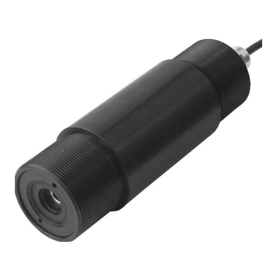
1 General notes 1.1 Intended use The sensors of the optris CX series are non-contact infrared temperature sensors. They calculate the surface temperature based on the emitted infrared energy of objects [► Basics of Infrared Thermometry]. The CX sensors are sensitive optical systems. Use the thread for mechanical installation only. -
Page 6: Warranty
In that case you may ask for a cost estimate beforehand. 1.3 Scope of delivery • optris CX incl. connection cable, mounting nut and user’s manual Read the manual carefully before the initial start-up. The producer reserves the right to change the herein described specifications in case of technical advance of the product. -
Page 7: Maintenance
Never use cleaning compounds which contain solvents (neither for the lens nor for the housing). Blow off loose particles using clean compressed air. The lens surface can be cleaned with a soft, humid tissue moistened with water or a water based glass cleaner. optris CX – E2014-09-A... - Page 8 CX – E2014-09-A...
-
Page 9: Technical Data
• Smart averaging means a dynamic average adaptation at high signal edges [activation via software only]. • If the unit is supplied together with the USB-kit (optional) the output will be set to digital communication (bidirectional). optris CX – E2014-09-A... -
Page 10: General Specifications
Dimensions: Diameter: 42 mm/ Length: 130 mm Weight: 350 g Cable length: Cable diameter: 4.3 mm Vibration: IEC 68-2-6: 3G, 11 – 200 Hz, any axis Shock: IEC 68-2-27: 50G, 11 ms, any axis optris CX – E2014-09-A... -
Page 11: Electrical Specifications
Power supply: 5...28 VDC inverted RS232-Signal, TTL, 9,6 kBaud white Current loop (+) yellow TxD (5 V) green RxD (5 V)/ Open-collector output brown Current loop (-)/ Ground (⊥) black Shield Figure 1: Wiring optris CX optris CX – E2014-09-A... -
Page 12: Measurement Specifications
0.100...1.100 (adjustable via software) Transmissivity: 0.100...1.000 (adjustable via software) Interface (optional): USB programming interface Signal processing: Average, peak hold, valley hold (adjustable via software) Software (optional): CompactConnect at ambient temperature of 23±5 °C; whichever is greater optris CX – E2014-09-A... -
Page 13: Optical Charts
The spot size refers to 90 % of the radiation energy. The distance is always measured from the front edge of the sensor housing. Figure 2: Optical chart optris CX (22:1) optris CX – E2014-09-A... -
Page 14: Cf-Optics And Protective Window
Figure 3: Optical chart optris CX with CF-lens (0.6 mm@ 10 mm) 2.6 CF-optics and protective window The optional CF-lens allows the measurement of small objects. For protection of the sensing head optics a protective window is available. The mechanical dimensions are equal to the CF lens. - Page 15 Figure 4: CF-lens [Order No.: ACCXCF]/ protective window [Order No.: ACCXPW] optris CX – E2014-09-A...
- Page 16 CX – E2014-09-A...
-
Page 17: Installation
Installation 3.1 Mechanical Installation The optris CX is equipped with a 20 UNF-2B thread and can be installed either directly via the sensor thread or with the help of the hex nut (standard) to the mounting bracket available. Figure 5: optris CX - Dimensions... - Page 18 Mounting bracket Figure 6: Mounting angle [Order No.: ACCXFB] and adjustment angle [Order No.: ACCXAB] for optris CX optris CX – E2014-09-A...
- Page 19 The needed amount of air (approx. 2...10 l/ min.) depends on the application and the installation conditions on-site. The lens must be kept clean at all times from dust, smoke, fumes and other contaminants in order to avoid reading errors. These effects can be reduced by using an air purge collar. optris CX – E2014-09-A...
- Page 20 Figure 7: Air purge collar [Order No.: ACCXAP]; Hose connection: 6x8 mm optris CX – E2014-09-A...
-
Page 21: Electrical Installation
Please use a stabilized power supply unit with an output voltage in the range of 5–28 VDC which can supply 100 mA. The residual ripple should be max. 200 mV. • Use shielded cables only. The sensor shield must be grounded. Figure 8: Wiring diagram of the analog device optris CX – E2014-09-A... - Page 22 Digital Communication For digital communication the optional USB programming kit is required. Figure 9: USB-Kit: USB programming adaptor incl. terminal block and software CD [Order No.: ACCSUSBK] optris CX – E2014-09-A...
- Page 23 1. Connect each wire of the USB adapter cable with the same colored wire of the sensor cable by using the terminal block. 2. To switch off a contact press the screw driver into the block as shown in figure 10. Figure 10: Connecting of the sensor cable and USB cable optris CX – E2014-09-A...
- Page 24 The sensor is offering two ways of digital communication: • bidirectional communication (sending and receiving data) • unidirectional communication (burst mode – the sensor is sending data only) Figure 11: Device with digital pin optris CX – E2014-09-A...
- Page 25 Analog + digital The optris CX is able to work in the digital mode and simultaneously as analog device (4-20 mA). In this case the sensor will be powered by the USB interface (5 V). Figure 12: Simultaneous analog and digital application...
- Page 26 Analog + alarm The alarm output (open collector output) can control an external relay. In addition the analog output can be used simultaneously. Figure 13: Analog device with alarm output optris CX – E2014-09-A...
-
Page 27: Software Compactconnect
• USB interface • Hard disc with at least 30 MByte of free space • At least 128 MByte RAM • CD-ROM drive A detailed description is provided in the software manual on the software CD. optris CX – E2014-09-A... - Page 28 The installation wizard will place a launch icon on the desktop and in the start menu: [Start]\Programs\CompactConnect. 3. Connect the optris CX via the USB interface with your the PC. To uninstall the software from your system use the uninstall icon in the start menu.
- Page 29 Main functions: • Graphic display for temperature trends and automatic data logging for analysis and documentation • Complete sensor setup and remote controlling • Adjustment of signal processing functions • Programming of outputs and functional inputs optris CX – E2014-09-A...
- Page 30 CX – E2014-09-A...
-
Page 31: Digital Command Set
Complete burst string Conversion to decimal value 2 synchronisation bytes: AAAA ------ ------ process temp [°C] = (Hex ⇒ Dec(03B8)-1000)/10 = -4,8 2 bytes for each output value (HI LO) 03B8 AAAA 03B8 Figure 15: Digital command set optris CX – E2014-09-A... - Page 32 CX – E2014-09-A...
-
Page 33: Basics Of Infrared Thermometry
Distance to Spot size. The spectral filter selects the wavelength range, which is relevant for the temperature measurement. The detector in cooperation with the processing electronics transforms the emitted infrared radiation into electrical signals. optris CX – E2014-09-A... - Page 34 CX – E2014-09-A...
-
Page 35: Emissivity
(reflective surfaces) carries the risk of inaccurate measuring results by interfering infrared radiation emitted by background objects (flames, heating systems, chamottes). To minimize measuring errors in such cases, the handling should be performed very carefully and the unit should be protected against reflecting radiation sources. optris CX – E2014-09-A... -
Page 36: Determination Of Unknown Emissivities
Afterwards, determine the temperature of a directly adjacent area and modify the emissivity until the measured value corresponds to the temperature of the colored surface. CAUTION: On all three methods the object temperature must be different from ambient temperature. optris CX – E2014-09-A... -
Page 37: Characteristic Emissivities
• temperature • measuring angle • geometry of the surface • thickness of the material • constitution of the surface (polished, oxidized, rough, sandblast) • spectral range of the measurement • transmissivity (e.g. with thin films) optris CX – E2014-09-A... - Page 38 CX – E2014-09-A...
-
Page 39: Appendix A - Table Of Emissivities For Metals
0,7-0,9 Iron non oxidized 0,05-0,2 non oxidized 0,05 rusted 0,5-0,7 Titanium polished 0,05-0,2 oxidized 0,5-0,9 oxidized 0,5-0,6 forged, blunt Wolfram polished 0,03-0,1 Iron, casted non oxidized Zinc polished 0,02 oxidized 0,6-0,95 oxidized Lead polished 0,05-0,1 optris CX – E2014-09-A... -
Page 40: Appendix B - Table Of Emissivities For Non-Metals
0,85 Grit 0,95 Gypsum 0,8-0,95 0,98 Limestone 0,98 Paint non alkaline 0,9-0,95 Paper any color 0,95 Plastic > 50 µm non transparent 0,95 Rubber 0,95 Sand Snow Soil 0,9-0,98 Textiles 0,95 Water 0,93 Wood natural 0,9-0,95 optris CX – E2014-09-A... -
Page 41: Appendix C - Direct Connection To An Rs232 Interface
Appendix C – Direct Connection to an RS232 Interface For a bidirectional RS232 connection of the sensor we recommend the interface circuit from Maxim, e.g. MAX3381E. optris CX – E2014-09-A... - Page 42 Model UART-Voltage (RxD) 3,3 V UART-Voltage (TxD) 2,5 V CX connections: TxD (yellow) an T1IN RxD (green) an R1OUT GND (brown) an GND PC connections: connect T1OUT with RxD (PC) connect R1IN with TxD (PC) optris CX – E2014-09-A...
-
Page 43: Appendix D - Smart Averaging
Therefore those peaks can only be seen with a delay on the signal output. The function Smart Averaging eliminates this disadvantage by passing those fast events without averaging directly through to the signal output. Signal graph with Smart Averaging function Signal graph without Smart Averaging function optris CX – E2014-09-A... -
Page 44: Appendix E - Ce-Conformity
Appendix E – CE-Conformity optris CX – E2014-09-A...
Need help?
Do you have a question about the optris CX and is the answer not in the manual?
Questions and answers