
Related Manuals for SEPTENTRIO AsteRx-U


Summary of Contents for SEPTENTRIO AsteRx-U
- Page 1 AsteRx-U User Manual...
- Page 2 September 08, 2015 Thank you for choosing the AsteRx-U! This user manual provides detailed instructions on how to use AsteRx-U and we recommend that you read it carefully before you start using the device. Please note that this manual provides descriptions of all functionalities of the AsteRx- U product family however, the particular AsteRx-U you purchased may not support functions speci c to certain variants.
-
Page 3: Table Of Contents
RTK ......... . . 32 OW TO CONFIGURE THE 4.1.1 How to con gure the AsteRx-U in RTK rover mode using the UHF radio . . 32 4.1.2 How to con gure the AsteRx-U in RTK rover mode using the cellular modem and NTRIP . - Page 4 LIST OF CONTENTS TERRASTAR OW TO CONFIGURE THE MODE USING ERIPOS ........52 OW TO CONFIGURE THE EADING PPS .
-
Page 5: Introduction
1 Introduction 1.1 User Notices 1.1.1 CE Notice AsteRx-U receivers carry the CE mark and are as such compliant with the 2004/108/EC - EMC Directive and amendments, 2006/95/EC - Low Voltage Directive, both amended by the CE-marking directive 93/68/EC. With regards to EMC, these devices are declared as class B, suitable for residential or business environment. -
Page 6: Support
1.1. USER NOTICES 1.1.4 Support For rst-line support please contact your AsteRx-U dealer. Further information can be found on our website or by contacting Septentrio Technical Support. http://www.septentrio.com support@septentrio.com septentrio_support Europe Septentrio NV Phone: +32 16 300 800 Greenhill Campus... -
Page 7: Asterx-U Overview
GNSS Heading, L-Band positioning and wireless communications within a rugged IP67 housing for the broadest range of applications. Use any smartphone, tablet or computer to operate the AsteRx-U without any special con guration software via the built-in webserver accessible via Wi-Fi, Ethernet or USB connection. - Page 8 • Integrated Bluetooth (2.1 + EDR/4.0) • Integrated Quadband Cellular Modem (EDGE, 2G, 3G, 3.5G) • Integrated Wi-Fi (802.11 b/g/n) • Integrated UHF (406-470 MHz) (AsteRx-U UHF and MARINE variants only) • Connector for separate L-Band antenna (AsteRx-U MARINE variant only)
-
Page 9: Asterx-U Variants
2.2. ASTERX-U VARIANTS 2.2 AsteRx-U variants The AsteRx-U is available in three variants: Variant Main features (Part number) • Integrated cellular modem AsteRx-U • Integrated Wi-Fi modem (410121) • Integrated Bluetooth modem • Integrated cellular modem AsteRx-U UHF • Integrated Wi-Fi modem (410119) •... -
Page 10: Asterx-U Design
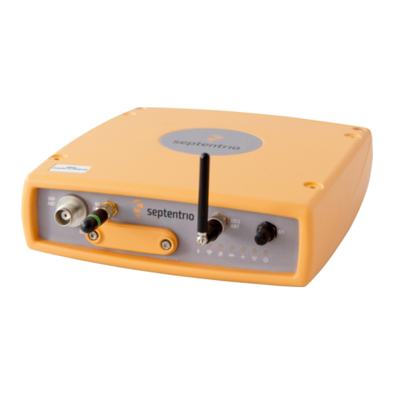
2.3. ASTERX-U DESIGN 2.3 AsteRx-U design 2.3.1 Front panel The front-panel layout of the AsteRx-U with attached Bluetooth/Wi-Fi and Cellular antennas is shown in Figure 2-1. Figure 2-1: AsteRx-U front-panel layout... -
Page 11: Led Description
2.3. ASTERX-U DESIGN 2.3.2 LED description Icon Behaviour Off: Bluetooth disabled On: Bluetooth connected blue Blinking slowly: Not connected but discoverable Off: Wi-Fi disabled On: Access-point mode or client mode Blinking slowly: Establishing a connection in client mode green Blinking quickly: Error, not connected Off: Not logging... -
Page 12: Rear Panel
Figure 2-2: AsteRx-U rear-panel layout 2.3.4 SIM card slot The SIM card can be inserted into the slot in the front panel of the AsteRx-U as shown in Figure 2-3. Important: Only insert or remove the SIM card while the unit is powered down. -
Page 13: Mounting Brackets
Figure 2-4: Mounting brackets tted to AsteRx-U 2.3.6 Internal memory The AsteRx-U has an 8 GB Memory for internal data logging. Data can be logged in SBF or NMEA format and may be retrieved via the logging tab of the web interface. -
Page 14: Shipping Case Contents
2.4. SHIPPING CASE CONTENTS 2.4 Shipping case contents 2.4.1 Supplied as standard The following items with their part numbers are supplied as standard with the AsteRx-U. -
Page 15: Optional Items
2.4. SHIPPING CASE CONTENTS 2.4.2 Optional items The following items with their part numbers can be optionally purchased for use with the AsteRx-U. -
Page 16: Quick Start
There is a power button on the front panel as shown in Figure 3-2 which you may also have to press. If the AsteRx-U loses power while the power button is on, then it will automatically boot up when power is restored. -
Page 17: Connecting An Antenna
3.2. CONNECTING AN ANTENNA 3.2 Connecting an antenna The rear panel of the AsteRx-U has two TNC connectors for GNSS antennas: one for the main antenna and one for an auxiliary antenna for heading applications. The AsteRx-U MARINE has an additional, TNC connector for a dedicated L-Band antenna. To get started, connect an antenna via an antenna cable to the main antenna connector of the AsteRx-U indicated in Figure 3-3. - Page 18 The USB connection on the AsteRx-U functions as network adapter and the DHCP server running on the receiver will always assign the AsteRx-U the IP address 192.168.3.1. To connect to the AsteRx-U, you can then simply open a web browser using the IP address 192.168.3.1 as shown in Figure 3-6.
-
Page 19: Using The Ethernet Cable
By default, the AsteRx-U has a DHCP address ‘http://Asterx-U-xxxxxxx’, where xxxxxxx are the 7 digits of the AsteRx-U serial number. The serial number can be found on a sticker on the corner of the outer casing of the receiver. Figure 3-8 shows a screenshot of an Ethernet connection to a receiver with serial number 3009165 using ‘http://asterx-u-3009165’. -
Page 20: Over Wi-Fi
Wi-Fi signals: the AsteRx-U identi es itself as a wireless access point named ’ A steRx-U-serial number’. The serial number of the AsteRx-U can be found on an identi cation sticker on the receiver housing. Select and connect to the AsteRx-U as shown in Figure 3-9. -
Page 21: How To Configure Sbf And Nmea Output
Step 1: Con gure the serial COM port The COM port of the AsteRx-U should be con gured with the same baud rate and ow control setting of the coupled device. These settings can be con gured via the ‘Communication’ tab as shown in Figure 3-11. - Page 22 3.4. HOW TO CONFIGURE SBF AND NMEA OUTPUT Step 2: Con gure data output NMEA In the ‘NMEA/SBF Out’ tab, clicking on ‘ A dd Stream’ will guide you through the steps needed to con gure NMEA output as shown in Figures 3-12 and 3-13. Figure 3-12: Selecting to output NMEA data on COM3 Figure 3-13: Selecting to output the GGA NMEA message every second...
- Page 23 3.4. HOW TO CONFIGURE SBF AND NMEA OUTPUT By clicking again on ‘ A dd Stream’, a second output stream can be con gured. In the example shown in Figures 3-14 and 3-15 the SBF PVTGeod data blocks will be output over COM1. Figure 3-14: Selecting to output SBF data on COM1 Figure 3-15: Selecting to output the PVTGeod SBF block every second...
- Page 24 3.4. HOW TO CONFIGURE SBF AND NMEA OUTPUT Step 3: Verifying the con guration Having con gured data output and clicked on ‘Ok’ the ‘NMEA/SBF Out’ page will now display a summary of all data output as shown in Figure 3-16. Figure 3-16: Summary of all con gured data output streams Figure 3-17 shows the actual data output.
-
Page 25: Output Over Ethernet
Figure 3-18, port 28785 has been con gured as connection IPS1 in box A. It is advisable to select a higher-range port to avoid those reserved for other purposes such as the webserver and FTP. Also, port 28784 is reserved by default on the AsteRx-U for commands. - Page 26 3.4. HOW TO CONFIGURE SBF AND NMEA OUTPUT Step 2: Con gure output of NMEA messages In the NMEA/SBF Out tab, click on ‘Add Stream’ and follow the sequence of windows to con gure the data you want to output. In the example shown in Figure 3-19, the NMEA GGA message will be output every second.
- Page 27 3.4. HOW TO CONFIGURE SBF AND NMEA OUTPUT Step 3: Con gure Data Link to listen for NMEA output The screenshots in Figure 3-20 show how the Septentrio GUI tool Data Link can be con gured to listen for the AsteRx-U GGA output.
-
Page 28: Output Over Bluetooth
NMEA data to an App called MachineryGuide on a Getac Android device. Step 1: con gure the bluetooth connection on the AsteRx-U On the Overview tab of the Web Interface, the you can make sure that Bluetooth has been enabled. - Page 29 3.4. HOW TO CONFIGURE SBF AND NMEA OUTPUT Step 2: Con gure NMEA messages to output In the ‘NMEA/SBF Out’ tab, click on ‘Add Stream’ as in Figure 3-24. This will guide you through the various steps shown in Figure 3-25 to con gure NMEA output. Select BT01 as the output communication port as shown.
- Page 30 Figures 3-26 and 3-27 show how the MachineryGuide App can be con gured to use NMEA data from the AsteRs-U over bluetooth. Figure 3-26: Select bluetooth for GPS positioning information Figure 3-27: Find and pair the device to the AsteRx-U...
- Page 31 3.4. HOW TO CONFIGURE SBF AND NMEA OUTPUT Step 4: Verifying the con guration When the AsteRx-U has been paired with a device and is sending data, the ‘In/Out’ graphic as shown in Figure 3-28 will indicate this. Figure 3-28: ‘NMEA/SBF out’ tab when AsteRx-U is bluetooth paired to a...
-
Page 32: Common Con Gurations
UHF radio When GMS/GPRS network coverage is either sparse or unreliable, RTK correction data can be transmitted over UHF radio. The AsteRx-U has build-in Satel radio modem that can be used to both receive and transmit data. -
Page 33: How To Configure The Asterx-U For Rtk
Figure 4-2: Con guring the built-in UHF radio After changing the settings on the web interface, they can be be sent to the AsteRx-U by clicking ‘OK’. Each time the con guration is changed, a pop-up in the lower right-hand corner will prompt you to save the new con guration as the boot con guration. - Page 34 4.1. HOW TO CONFIGURE THE ASTERX-U FOR RTK Step 3: Verifying the con guration If the UHF radio of the AsteRx-U has been correctly con gured then you should see in the UHF/DiffCorr eld, the greyed-out connection line now replaced by a ‘live’ green line as in Figure 4-3.
-
Page 35: How To Con Gure The Asterx-U In Rtk Rover Mode Using The Cellular
4.1. HOW TO CONFIGURE THE ASTERX-U FOR RTK 4.1.2 How to con gure the AsteRx-U in RTK rover mode using the cellular modem and NTRIP Step 1: Enable RTK mode Ensure that RTK is be enabled as a positioning mode. This can be done in the GNSS Position tab by checking the ‘RTK’... - Page 36 4.1. HOW TO CONFIGURE THE ASTERX-U FOR RTK Step 2: Con gure the cellular modem Insert a SIM card into the front-panel slot of the AsteRx-U as shown in Figure 2-3 while the unit is powered down. The on-board cellular modem of the AsteRx-U can con gured in the Communication Cellular window as shown in Figure 4-5.
- Page 37 Using a cellular connection you can get RTK correction data from an NTRIP service. Figure 4-7 shows the settings required to retrieve correction data from the Septentrio NTRIP Caster. Select ‘Client’ from the drop-down Mode menu. The Caster, Port, User Name and Password should be provided by the NTRIP service.
- Page 38 4.1. HOW TO CONFIGURE THE ASTERX-U FOR RTK Step 4: Verifying the con guration When both the cellular modem and NTRIP connection have been correctly con gured, the Ntrip gure in Corrections NTRIP window will indicate diff corr reception as shown in Figure 4- 9 with the positioning mode icon indicating RTK xed.
-
Page 39: How To Con Gure The Asterx-U In Rtk Rover Mode Using Tcp/Ip In A
Step 1: Con gure the Base station receiver Set the Base station position as static Section 4.2 describes how to con gure the AsteRx-U as an RTK base station. Con gure the Ethernet connection of the Base station receiver The Ethernet connection over which the correction data will be sent can be con gured in the Communication Ethernet tab as shown in Figure 4-10. - Page 40 4.1. HOW TO CONFIGURE THE ASTERX-U FOR RTK Con gure output of differential corrections In the Corrections Output window shown in Figure 4-11 click on ‘ A dd Stream’ to con gure the output of differential corrections from the base station receiver. Make sure to check the box to output on the port you have just con gured which in this example is ‘IPS1’.
- Page 41 4.1. HOW TO CONFIGURE THE ASTERX-U FOR RTK Step 2: Con gure the Rover receiver Enable RTK positioning mode on the rover receiver Ensure that RTK is be enabled as a positioning mode. This can be done in the GNSS Position tab by checking the ‘RTK’...
- Page 42 4.1. HOW TO CONFIGURE THE ASTERX-U FOR RTK Step 3: Verifying the con guration If the Base station and rover receivers have been con gured correctly then graphics in the Communication Ethernet windows should appear similar to those shown in Figures 4-14 and 4-15.
-
Page 43: How To Configure The Asterx-U As An Rtk Base Station
Set the position as static To work as a base station, the position of the AsteRx-U should be static. If the position is not static, the AsteRx-U can still work as a base station however the position of the rover may show more variation. - Page 44 4.2. HOW TO CONFIGURE THE ASTERX-U AS AN RTK BASE STATION Figure 4-17: Setting the static position to the pre-set ‘Geodetic1’ position Click on ‘OK’ to apply the new settings Step 2: Con gure output of differential corrections Con gure the correction stream On the ‘Corrections Output’...
- Page 45 Figure 4-19 shows the settings required on the ‘UHF’ tab to setup the AsteRx-U to transmit correction data over a frequency of 410 MHz, channel spacing of 25 kHz and at a power of 100 mW. The transmission protocol and error method can also be selected on this page as shown.
- Page 46 4.2. HOW TO CONFIGURE THE ASTERX-U AS AN RTK BASE STATION Step 3: Verifying the con guration Having con gured the settings and clicked on ‘OK’ to apply them, the greyed-out transmission line in the top-panel should change to green as shown in Figure 4-20. The format of the corrections stream should also be correctly identi ed.
-
Page 47: H Ow To Configure The A Ste R X -U In Ppp Mode Using Terrastar Or V Eripos
4.3. HOW TO CONFIGURE THE ASTERX-U IN PPP MODE USING TERRASTAR OR VERIPOS 4.3 How to con gure the AsteRx-U in PPP mode using TERRASTAR or Veripos Precise Point Positioning (PPP) provides high accuracy positioning without the need for a local base station. - Page 48 You can nd out more about Veripos subscriptions via the link: http://www.veripos.com/services.html. You will be asked to provide the Augmentation User ID of the AsteRx-U which can be seen in the Veripos window and is shown highlighted in Figure 4-22.
- Page 49 4.3. HOW TO CONFIGURE THE ASTERX-U IN PPP MODE USING TERRASTAR OR VERIPOS Step 3: Select PPP positioning Ensure that PPP is selected as a positioning mode in the GNSS Position tab as shown in Figure 4-24. Figure 4-24: Enable PPP positioning mode Step 4: Beam Selection Mode and Service For TERRASTAR con guration, select the tab named ‘TERRASTAR’...
- Page 50 4.3. HOW TO CONFIGURE THE ASTERX-U IN PPP MODE USING TERRASTAR OR VERIPOS Without a TERRASTAR or Veripos subscription, the AsteRx-U will still be able track visible L- Band signals. Figure 4-26 shows the L-Band Tracker Status eld when the AsteRx-U is locked onto signals from the AORE satellite which transmits at 1539.9825 Mz.
- Page 51 4.3. HOW TO CONFIGURE THE ASTERX-U IN PPP MODE USING TERRASTAR OR VERIPOS If the con guration is correct and the PPP subscription is valid then the AsteRx-U positioning mode should change to DGPS followed by PPP. Figure 4-28 shows the PPP positioning icon that should appear on the upper status eld.
-
Page 52: Aste R X -Uin Ppp Mode Using Aste R X -Ufor Heading
Figure 4-30: Auxiliary antenna connector on rear panel Step 2: Con gure Heading settings You can con gure and review the heading settings of the AsteRx-U in the GNSS Heading tab as shown in Figure 4-31. Figure 4-31: GNSS Heading tab... - Page 53 Figure 4-32: Recommended settings for Heading Antenna Location and Antenna Offset The AsteRx-U assumes that the main and auxiliary antennas are placed along the longitudinal axis of the vehicle with the auxiliary in front of the main antenna. If the antennas cannot be placed in such a con guration, the reported heading and pitch may be biased.
- Page 54 Figure 4-35: Selecting all attitude SBF blocks by checking the ‘ A ttitude’ box NMEA You can output the attitude information from the AsteRx-U in NMEA format by selecting the standard NMEA HDT sentence or the Septentrio proprietary HRP sentence as shown in Figure 4-36.
-
Page 55: How To Output A
4.5. HOW TO OUTPUT A PPS 4.5 How to output a PPS The AsteRx-U can output a PPS (Pulse-per-Second) signal that can be used for example, to synchronise a secondary device to UTC time. Step 1: Connect the PPS cable Connect the PPS_OUT cable to the rear-panel connector labelled ‘PPS GPO’... - Page 56 4.5. HOW TO OUTPUT A PPS The Delay argument can be used to compensate for signal delays in the system (including antenna, antenna cable and PPS cable). For example, if the antenna cable is replaced by a longer one, the overall signal delay could be increased by say, 20 nsec. If Delay is left unchanged, the PPS pulse will come 20 ns too late.
-
Page 57: Using The Spectrum Analyser To Detect And Mitigate Interference
4.6. USING THE SPECTRUM ANALYSER TO DETECT AND MITIGATE INTERFERENCE 4.6 Using the spectrum analyser to detect and mitigate interference The spectrum view plot In the GNSS Spectrum tab, you can monitor the RF spectrum and con gure three separate notch lters to cancel out narrowband interferences. - Page 58 4.6. USING THE SPECTRUM ANALYSER TO DETECT AND MITIGATE INTERFERENCE Con guring the notch lters In the default auto mode of the notch lters, the receiver performs automatic detection of the region of the spectrum affected by interference if any. In manual mode as shown con gured for Notch1 in Figure 4-40, the region of the spectrum speci ed by a center frequency and a bandwidth is blanked by the notch lter.
-
Page 59: Receiver Administration Operations
The IP settings of the AsteRx-U can be con gured on the Communication Ethernet tab of the Web Interface. By default the AsteRx-U is con gured to use DHCP to obtain an IP address. You can specify a ‘Static’ address in the TCP/IP Settings eld as shown highlighted in Figure 5-1. - Page 60 5.1. HOW TO CHANGE IP SETTINGS OF THE ASTERX-U After reboot, the Ethernet Status eld should now show the correct IP settings as shown in Figure 5-2. Figure 5-2: TCP/IP settings Note that the IP settings will keep their value after a power cycle and even after a reset to...
-
Page 61: How To Upgrade The Firmware Or Upload A New Permission File
.suf (Septentrio Upgrade Format) and can be uploaded to the AsteRx-U as shown in the steps below. Firmware upgrades can be downloaded from the Septentrio website and are free for the lifetime of the receiver. Permission les enable additional features on the AsteRx-U and can be purchased via our sales department. - Page 62 Step 2: Verifying the upgrade If there were no problems with the upgrade the message ‘Upgrade successful’ will appear. You can then check on the Admin About tab that the AsteRx-U rmware or permission le has correct, new version as indicated in Figure 5-5.
-
Page 63: How To Set The Aste
Figure 5-7, different functionalities can be individually reset. A ‘Soft’ level reset will cause the AsteRx-U to boot up with its current con guration while a ‘hard’ reset will use the con guration stored in the boot le. -
Page 64: How To Copy The Configuration From One Receiver To Another
5.5 How to copy the con guration from one receiver to another In the Admin Con gurations tab, the con guration of an AsteRx-U can be easily saved to a PC as a text le. A saved con guration can also be uploaded to an AsteRx-U. - Page 65 5.5. HOW TO COPY THE CONFIGURATION FROM ONE RECEIVER TO ANOTHER Select the con guration le to be uploaded then click on OK on the status pop-up as shown in Figure 5-10. Figure 5-10: Select the con guration le to upload...
-
Page 66: Rear-Panel Port Descriptions
6 Appendix 6.1 Rear-panel port descriptions 6.1.1 PPS/GPO Figure 6-1: 5-pin female socket pin-numbering guide. Start counting at pin indicated by bold semi-circle and follow the line in a clockwise direction. Note that the numbering is reversed for the male cable socket. PIN # Name Comment... -
Page 67: Com2
6.1. REAR-PANEL PORT DESCRIPTIONS 6.1.3 COM2 Figure 6-3: 9-pin female socket pin-numbering guide. Start counting at pin indicated by bold semi-circle and follow the line in a clockwise direction. Note that the numbering is reversed for the male cable socket. PIN # Name Comment... -
Page 68: Ethernet/Usb
6.1. REAR-PANEL PORT DESCRIPTIONS 6.1.5 Ethernet/USB Figure 6-5: 16-pin female socket pin-numbering guide. Start counting at pin indicated by bold semi-circle and follow the line in a clockwise direction. Note that the numbering is reversed for the male cable socket. PIN # Name Comment... -
Page 69: Com1/Com3/Host Usb
6.1. REAR-PANEL PORT DESCRIPTIONS 6.1.6 COM1/COM3/Host USB Figure 6-6: 14-pin female socket pin-numbering guide. Start counting at pin indicated by bold semi-circle and follow the line in a clockwise direction. Note that the numbering is reversed for the male cable socket. The USB Host feature will only become fully functional in later rmware versions.
Need help?
Do you have a question about the AsteRx-U and is the answer not in the manual?
Questions and answers