
Related Manuals for Teridian TFP2


Summary of Contents for Teridian TFP2
- Page 1 A Maxim Integrated Products Brand Flash Programmer Model TFP2 USER’S MANUAL August 8, 2011 Revision 2.3...
- Page 2 Flash Programmer Model TFP2 User’s Manual Revision History Revision Date Description 4/27/2007 Initial release. 2/4/2009 Added note for ICE enable pin. 10/20/2010 Added Order Number. 8/8/2011 Added troubleshooting tips. Replaced TFP2 photos. Maxim cannot assume responsibility for use of any circuitry other than circuitry entirely embodied in a Maxim product. No circuit patent licenses are implied.
-
Page 3: Table Of Contents
Flash Programmer Model TFP2 User’s Manual Table of Contents GETTING STARTED......................... 5 1.1 General ............................5 1.2 Safety and ESD Notes ....................... 5 1.3 Kit Contents ..........................6 1.4 Compatibility ..........................6 1.5 Suggested Equipment not Included ..................6 PC USER INTERFACE ........................7 2.1 TFP2 CHKSUM.EXE Utility ...................... - Page 4 Figure 2-3: TFP2 Power-Up Information Display ..................8 Figure 2-4: TFP2 Help Menu........................9 Figure 2-5: TFP2 Intel Hex File Download to Internal EEPROM Command ..........11 Figure 2-6: TFP2 Select Target Intel Hex File ..................11 Figure 2-7: TFP2 Download in Progress ....................11 Figure 2-8: TFP2 Download Complete ....................
-
Page 5: Getting Started
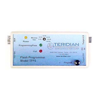
Standalone operation only performs the target FLASH memory programming. Once programmed, the target’s FLASH memory contents are verified and a PASS or FAIL indication is reported. The TFP2 front panel incorporates two status LEDs. These status indications are also provided at the ATE connector and displayed by the PC User Interface. -
Page 6: Kit Contents
Flash Programmer Model TFP2 User’s Manual 1.3 KIT CONTENTS Model TFP2 Flash Programmer 5VDC/1,000mA universal wall transformer with 2.5mm plug Serial cable, DB9, Male/Female, straight cable, 2m length (Digi-Key AE1020-ND) ATE cable housing and crimp pins ... -
Page 7: Pc User Interface
2 PC USER INTERFACE 2.1 TFP2 CHKSUM.EXE UTILITY Prior to downloading the target’s hex file to the TFP2, the target’s hex file must be pre- processed using the CHKSUM.EXE utility provided with the enclosed diskette. A hex file not processed with CHKSUM.EXE will result in incomplete programming of the target’s FLASH memory. -
Page 8: Figure 2-2: Chksum.exe Warning Display
Either the CHKSUM.EXE calculated CRC and checksum bytes are copied or the original target’s hex data are copied. If the last two bytes of the target hex file are 0xFF (CHKSUM not used), the TFP2 overwrites the last two 0xFF bytes with its calculated checksum during the Hyper-Terminal file Download operation. -
Page 9: Figure 2-4: Tfp2 Help Menu
Figure 2-4: TFP2 Help Menu Commands C, E, T, V, Z and ? are single keystroke events (no further user action required until the TFP2 completes the intended task). The D, H and P commands require additional user action and are... -
Page 10: Table 2-2: Chksum Utility Output Data
The TFP2 programs into the target memory what was previously downloaded (once downloaded, the last two words do not change during programming). The TFP2 then verifies the target memory to its internal memory resulting in the correct PASS indication even when user data is present. -
Page 11: Tfp2 Eeprom Download
Flash Programmer Model TFP2 User’s Manual 2.2 TFP2 EEPROM DOWNLOAD Transfer of the target’s code from a PC to the TFP2 begins with the “H” command. The target code file must have been preprocessed using the CHKSUM.EXE utility provided on the enclosed diskette. Refer Section 2.1... -
Page 12: Figure 2-8: Tfp2 Download Complete
PASS and FAIL indication. Additionally, the appropriate green or red LED is illuminated. The TFP2 EEPROM checksum calculation value is based on the memory size switch setting and is displayed for future reference. The download transfer times ... -
Page 13: Target Flash Memory Programming
Programming of the target’s FLASH memory begins with typing “P” followed by the “Enter” key. The green LED on the TFP2’s front panel blinks while the target FLASH memory is being mass erased, programmed and verified. The red LED will momentarily flash on at the start of programming. Upon completion of the target FLASH memory programming the following display appears. -
Page 14: Previously Programmed Device Verification
A previously programmed device can be checked against the currently loaded image contained in the TFP2. Use the “C” command to perform this comparison. The green LEDs are illuminated if the flash contents of the device in the socket match the contents of the TFP2 EEPROMs. -
Page 15: Device Status Check
FLASH memory, i.e. – code patch or parameters. Use the “D” command to download a code patch or a parameter table to the TFP2 EEPROM without erasing and reprogramming the entire TFP2 EEPROM memory. The memory locations to be reprogrammed are read from the downloaded Hex File. -
Page 16: Figure 2-17: Parameter Mode Selection
The location of the 4KB parameter space depends on the target device’s FLASH memory size. The TFP2 determines the target FLASH memory size from the front panel Memory Size switch. The following table shows the reserved address locations of parameter space for different memory sizes. -
Page 17: Figure 2-18: Parameter Mode Status
Flash Programmer Model TFP2 User’s Manual Figure 2-18: Parameter Mode Status Revision 2.3 17 of 36... - Page 18 Flash Programmer Model TFP2 User’s Manual Revision 2.3 18 of 36...
-
Page 19: Target Code Initialization
Before the target’s FLASH memory can be programmed, the target code must be transferred to the TFP2 for internal storage. First configure the TFP2 for the proper memory size of the target’s code. Rotate the internal Memory Size rotary switch to the appropriate position. There is a black arrow on top of the rotary switch shaft denoting the switch position. -
Page 20: Power Supply Connection
Figure 3-3: Port Speed, Port Bit Setup and Flow Control Once, communication to the TFP2 is established, press the “Enter” key and the TFP2 program prompt “>” should appear. Typing “?“ displays the TFP2 program help menu. Type “V“ to verify that the TFP2 program version is revision 1.00 or later. -
Page 21: Target Flash Memory Programming
Flash Programmer Model TFP2 User’s Manual 4 TARGET FLASH MEMORY PROGRAMMING The TFP2 Flash Programmer connects to the target board via one of two connectors: 1) The Target-LS connector provides connection using discrete wires. Target- Only use this interface for TCLK frequencies of 10 MHz or less. -
Page 22: Figure 4-3: Target-Ls Connector Pin Locations (Looking At Tfp2 Endplate)
Figure 4-3: Target-LS Connector Pin Locations (looking at TFP2 endplate) The TFP2 does not supply power at the Target-LS connector. Power must be supplied to the target board separately. The TFP2 must be powered first before connecting the target board to the TFP2. -
Page 23: Standalone Programming
Figure 4-4: Target-HS Connector Pin Locations (looking at TFP2 endplate) The TFP2 does not supply power at the Target-HS connector. Power must be supplied to the target board separately. The TFP2 must be powered first before connecting the target board to the TFP2. -
Page 24: Pc User Interface Programming
NOTE: The TFP2 must be powered first before connecting the target board to the TFP2. Do not connect a PC to the TFP2 AND connect the TFP2 to a target board with any connection to Line or Neutral. Equipment damage will occur due to a Ground signal disparity or live voltages. -
Page 25: Figure 4-7: Ate Connector Pin Locations (Looking At Tfp2 Endplate)
Output Active HI signal indicates target FLASH Memory failed verification. FAIL goes low when PROGRAM is re-asserted FAIL high. FAIL toggles HI and LO if the TFP2 cannot communicate with the target board. Ground Table 4-3: ATE Connector Pins Figure 4-7: ATE Connector Pin Locations (looking at TFP2 endplate) ATE Connector part numbers: 1. -
Page 26: Figure 4-8: Program Flow Chart
The PROGRAM ACTIVE, PASS and FAIL outputs incorporate 62Ω series resistors. The flow chart shown in Figure 3-9 details the programming sequence required of the ATE (must apply power to TFP2 Flash Programmer before the sequence below begins). Turn-on power to... -
Page 27: Boot Loader
Flash Programmer Model TFP2 User’s Manual 5 BOOT LOADER The TFP2 Boot Loader enables the TFP2 firmware to be upgraded in the field (remote location). The Teridian Semiconductor provided TFP2 firmware file is first downloaded to the TFP2’s EEPROM. Transfer of this revised firmware file from the TFP2’s EEPROM to its local program memory is performed by typing “BOOT”... -
Page 28: Figure 5-2: Tfp2 Boot Completion
If the internal TFP2 EEPROM contents are corrupted (checksum comparison failure) or if the EEPROM contents do not represent a TFP2 code file (user’s target code), the BOOT command will NOT reprogram the TFP2. The current power-on screen is immediately displayed with no flashing PASS led when a problem is encountered with the EEPROM contents. -
Page 29: Status Indications
1. Red LED blinks after power-on – Incorrect Memory Switch setting: either position 6 or 7 selected. 2. Red LED on 100% after TFP2 download – TFP2 download CRC failed. 3. Red LED on 100% immediately upon Target programming – Target not responding upon attempted programming. - Page 30 Flash Programmer Model TFP2 User’s Manual Revision 2.3 30 of 36...
-
Page 31: Tfp2 Hardware Specifications
Flash Programmer Model TFP2 User’s Manual 7 TFP2 HARDWARE SPECIFICATIONS Case Dimensions Dimensions 6.0” x 2.5” x 1.5” Weight 0.35 lbs. Environmental • Operating Temperature +10°…+50°C • Storage Temperature -40°C…85°C Power Supply Supply Voltage +5VDC +/- 10% regulated ... - Page 32 Flash Programmer Model TFP2 User’s Manual Revision 2.3 32 of 36...
-
Page 33: Troubleshooting
Match between selected flash program size and target flash size When the programming process seems to fail, it is useful to watch the feedback messages from the TFP2 via HyperTerminal. Using the C and/or T commands it can be determined quickly if the issue is with the communication link or somewhere else. -
Page 34: Verification Errors
A typical dialog involving a verification error is shown below. In this case, the communication between TFP2 and the target IC was established, but the programmed target image had at least one error, which was discovered during the verify process. -
Page 35: Ordering Information
Flash Programmer Model TFP2 User’s Manual 9 ORDERING INFORMATION The following table lists the order number used to identify the TFP2 Flash Programmer. Table 9-1: Order Number Part Description Order Number Flash Programmer Model TFP2 80515-FPBM-TFP2 Revision 2.3 35 of 36... - Page 36 Flash Programmer Model TFP2 User’s Manual Revision 2.3 36 of 36...
- Page 37 Mouser Electronics Authorized Distributor Click to View Pricing, Inventory, Delivery & Lifecycle Information: Maxim Integrated 80515-FPBM-TFP2...
Need help?
Do you have a question about the TFP2 and is the answer not in the manual?
Questions and answers