Table of Contents
Advertisement
Advertisement
Table of Contents

Related Manuals for DSC LE4000


Summary of Contents for DSC LE4000
- Page 1 LE4000 LTE Wireless Alarm Communicator Installation Manual V5.0 Warning: This manual contains information on limitations regarding product use and function and information on the limitations as to liability of the manufacturer. The entire manual should be carefully read.
-
Page 2: Table Of Contents
LE4000 Installation Manual Table of Contents Section 1: Introduction 1.1 Features 1.2 Technical Specifications Section 2: Identification of Parts Section 3: Installing the LE4000 Section 4: Connecting the LE4000 Section 5: Status LEDs 5.1 Operating Modes 5.2 Normal Mode 5.3 Service Mode Section 6: Operating Principles 6.1 Simulated Landline Mode... - Page 3 Approvals Information For UL Residential Fire and Burglary installations, the LE4000 is listed as a sole means of communication or as a back up when used in conjunction with a POTS line (dialer). For UL Residential Fire installations, the LE4000 must be connected to a UL-listed power supply with a minimum of 24 hours standby power or powered using the ADP 1310(W)-NAU and a 2200mAh battery.
-
Page 4: Section 1: Introduction
Section 1: Introduction The LE4000 is a cellular communicator that sends alarm system information to a Sur-Gard System I-IP, II, III, IV or 5 receiver through an LTE or 3G wireless network. This cellular communicator can be used with UL/ULC Listed compatible control units, as indicated in the manufacturer's installation instructions. - Page 5 1.2 Technical Specifications Battery Charging Current: 160mA Battery Standby Time: 24 hours NOTE: Battery must be replaced every 3-5 years. Cellular Bands B2, B5. Bands B2, B4, B5, B12, B13 (see Table 3-1 : Band Frequencies) Antenna Gain 2.0 dBi Environmental Specifications Operating temperature: 0°C-49°C (32°F-120°F)
-
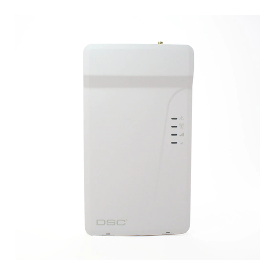
Page 6: Section 2: Identification Of Parts
LTE external antenna* Antenna mounting hardware Wall tamper switch Cover tamper switch Status LEDs (see "Status LEDs" on page 11) PC-Link connector Battery connector Terminal blocks Cable entry 7.2V - 2.2Ah battery (optional) Cable run knockout * Use only DSC provided antenna. -
Page 7: Section 3: Installing The Le4000
Blue/Green (Bottom) If the signal strength is too low (bottom signal LED off or flashing), the LE4000 will move to Step 3 and scan for carriers with suf- ficient signal strength and attach to the carrier. If the LE4000 is connected to a carrier with sufficient signal strength (minimum of bot- tom signal strength LED on solid), it will move to Step 4. - Page 8 Step 4 - Acquire C24 Communications Programming The red LED will be on solid and the blue LED will flash. The flashing of the blue LED indicates that the LE4000 has requested pro- gramming from C24 Communications and is waiting for a response.
- Page 9 Step 6 - Mount the LE4000 Note: If using an LE4000 trim plate, snap the LE4000 back plate onto the trim plate before mounting to the wall. If flush mounting or using with an extension antenna, remove the provided breakaway from the trim plate prior to mounting.
-
Page 10: Section 4: Connecting The Le4000
LE4000 Installation Manual Section 4: Connecting the LE4000 TIP (1) / RNG (2) External Telephone Line - If the LE4000 is being used as a back-up communicator, these terminals must be con- nected directly to the incoming telephone line. T1 (3) / R1 (4) Internal Telephone Line - These terminals must be connected to the TIP and RING of the control panel. -
Page 11: Section 5: Status Leds
If this LED is off and the Red LED is on, the wireless network service is unavailable (NO SERVICE). This LED flashes when wireless network reception is poor. If this LED is on, the LE4000 is able to communicate with the LTE or 3G... -
Page 12: Service Mode
LE4000 Installation Manual 5.3 Service Mode To view detailed trouble information on the status LEDs, place the LE4000 in Service mode by removing the front cover. When in Ser- vice mode, the status LEDs indicate troubles as follows. Number of Flashes... -
Page 13: Section 6: Operating Principles
Once the conditions for a failed attempt are met, the LE4000 connects the panel to the cellular network to communicate the events. When the LE4000 switches the line it stays in this mode until the panel hangs up. On the next event the LE4000 restarts the error detection sequence before switching. -
Page 14: Inputs
6.5.1 Activating the Outputs The LE4000 has two open collector outputs capable of a maximum of 50mA. Internal events on the LE4000 can trigger the outputs to turn on an LED or activate an input on the host panel. The default settings are as follows. -
Page 15: Swinger Shutdown
6.7 Swinger Shutdown To prevent "runaway" signals to the central station, the LE4000 is equipped with Swinger Shutdown which limits certain trouble events to a maximum of four reports every 24 hours. At midnight, the condition restores and the counter is reset. Swinger Shutdown... -
Page 16: Low Power Radio Shutdown
• Low Battery Trouble 6.10 Low Power Radio Shutdown When the battery voltage reaches the low battery threshold of 6V, the LE4000 turns off the radio to prevent unnecessary network registrations. In this state, no events are communicated. Radio shutdown is indicated by the LEDs as follows: Red LED indicates low battery trouble. - Page 17 6.11.2 Remote Control of PGM 2. Via C24 Communications, program the phone number and access code used for SMS command and control. Up to 6 different phone numbers can be programmed to perform SMS command and control. The password can be 4 to 8 alphanumeric characters and is not case sensitive. The SMS command and control can be sent in the following format: For arming/disarming the security panel Arm <access code>, example Arm 12345678...
-
Page 18: Phone Number Call Direction
LE4000 Installation Manual Help Language Command Label (shall not be case sensitive) English Help French Aide Spanish Ayuda Help displays all available commands for the selected language. 6.12 Phone Number Call Direction The user has the ability to program the PTM phone numbers to receiver group 1 or 2. -
Page 19: Section 7: Troubleshooting Guide
SIM – the SIM should be activated at least 24 hours prior to installation. The LE4000 will show signal strength with an inactive SIM, however it will display the signal strength of any available wireless network. - Page 20 The Red light flashes to indicate various trouble conditions outlined previously. If multiple trouble conditions are present, the red LED flashes according to the highest priority trouble. For example, if both a LE4000 wireless network trouble (one flash) and a low battery trouble (two flashes) are present;...
- Page 21 Section 7: Troubleshooting Guide General Troubles With Your System The control panel is displaying a tele- Ensure T1 and R1 of the LE4000 are wired to the TIP and RING terminals of the control phone line trouble condition panel. If the LE4000 is being used as the primary communicator, the blue light will always be OFF.
-
Page 22: Section 8: Le4000 Wiring Diagrams
LE4000 Installation Manual Section 8: LE4000 Wiring Diagrams Figure 8-1 LE4000 Wiring Diagram... - Page 23 When the Radio is powered by the control panel the relay is not required since a loss of input power will generate a signal to the CMC. 3. PGM2 on the LE4000 must be set as “Active Control Panel High”...
- Page 24 LE4000 cabinet 5. 24hr Test Transmission over phone line (PSTN) and LE4000 must be enabled. 6. Connect an output (PGM) from Alarm Control panel to an input on the LE4000 to monitor the T1/R1 connection. AC Input Keypad Figure 8-4 Alarm Control Unit and LTE/3G Transmitter...
- Page 25 LIMITED TO, LOSS OF PROFITS, LOSS OF THE SOFTWARE PRODUCT OR ANY ASSOCIATED fication of any previous arrangement or contract. If You do not agree to the terms of this EULA, DSC is EQUIPMENT, COST OF CAPITAL, COST OF SUBSTITUTE OR REPLACEMENT EQUIPMENT, unwilling to license the SOFTWARE PRODUCT to You, and You have no right to use it.
- Page 26 (e.g., 03 is a REN of 0.3). For earlier products, the REN is separately shown on the label. Incidence of Harm If this equipment LE4000 causes harm to the telephone network, the telephone company will notify you in advance that temporary discontinuance of service may be required. But if advance notice is not practical, the Telephone Company will notify the customer as soon as possible.
- Page 27 The Customer assumes all responsibility for the proper selection, installation, operation and maintenance of any products purchased from DSC. Custom products are only warranted to the extent that they do not function upon delivery. In such cases, DSC can replace or credit at its option.
Need help?
Do you have a question about the LE4000 and is the answer not in the manual?
Questions and answers