DSC PC1550 Installation Manual
Hide thumbs
Also See for PC1550:
- Installation manual (25 pages) ,
- Instruction manual (12 pages) ,
- Instruction manual (9 pages)
Table of Contents
Advertisement
Quick Links
TABLE OF CONTENTS
Mounting the Panel ............................................................... 3
Mounting the Keypad ........................................................... 3
Auxiliary Power Connection .................................................. 3
PGM Terminal Connections .................................................. 3
Bell/Siren Connection ........................................................... 3
Keypad Wiring ...................................................................... 3
Fire Zone Wiring .................................................................... 3
Burglary Zone Wiring ............................................................ 3
Battery Connection ............................................................... 3
Telephone Line Wiring .......................................................... 3
Introduction ........................................................................... 5
Master Code ......................................................................... 5
2nd Master Code .................................................................. 5
Installer's Programming Code .............................................. 5
Arming .................................................................................. 5
Auto-Bypass/Home-Away Arming ........................................ 5
Arming Without Entry Delay .................................................. 5
Disarming .............................................................................. 5
Zone Bypassing [ ]+[1] ....................................................... 5
Trouble Conditions [ ]+[2] ................................................... 5
Alarm Memory [ ]+[3] .......................................................... 6
Downloading Callup Command [ ]+[4] ............................... 6
User Programming Commands [ ]+[5] ............................... 6
EEPROM Reset ..................................................................... 6
User Function Commands [ ]+[6]+[Master Code] .............. 6
[ ]+[7] or [ ]+[7]+[Access Code] ............................ 7
[ ]+[8]+[Installer's Code] ........................................... 7
Arming without Entry Delay [ ]+[9]+[Access Code] ........... 7
Arming For The Night [ ]+[1] ............................................... 7
Quick-Exit Command [ ]+[0] when armed .......................... 7
Quick-Arm Command [ ]+[0] .............................................. 7
Keypad Zones ...................................................................... 7
How to Program .................................................................... 8
Program Data Review ........................................................... 8
Binary Data Display .............................................................. 8
HEX Data Programming ........................................................ 8
Programming Sections ......................................................... 8
[00] Binary Programming ................................................. 8
[01] 1st Phone Number .................................................... 8
2
[02] 1st Account Code ..................................................... 8
2
[03] 2nd Phone Number ................................................... 9
[04] 2nd Account Code .................................................... 9
3
[05] to [10] Reporting Codes ........................................... 9
[05] Zone Alarm Reporting Codes ................................... 9
[06] Zone Restoral Reporting Codes .............................. 9
Partial Closing Reporting Code ................................ 9
After Alarm Reporting Code ...................................... 9
[09] Priority Alarms and Restorals .................................... 9
[10] Maintenance Alarms and Restorals ........................ 10
[11] Zone Definitions ...................................................... 10
[12] 1st System Option Code ......................................... 11
[13] 2nd System Option Code ....................................... 11
[14] 3rd System Option Code ........................................ 11
[15] Communication Variables ....................................... 11
5
[16] Zone Bypass Mask ................................................. 11
[17] System Times .......................................................... 11
[18] Auxiliary Delay Loop Entry/Exit Times .................... 12
[19] System Clock Times ............................................... 12
[20] New Installer's Code ............................................... 12
[21] New Master Code ................................................... 12
[22] 2nd Master Code ................................................... 12
[23] Communication Formats ........................................ 12
[25] Communicator Call Directions ................................ 13
[26] Downloading Telephone Number ........................... 13
[27] Downloading Access Code .................................... 13
[28] Panel Identification Code ........................................ 13
[29] Number of Rings Before Answering ....................... 13
[30] Reset to Factory Default ......................................... 13
[31] 4th System Option Code ......................................... 14
[32] 5th System Option Code ......................................... 14
[33] Answering Machine Double Call Timer .................. 14
[34] 6th System Option Code ......................................... 14
[35] LINKS1000 Test Reporting Code ........................... 14
[36] Keypad Lockout Control ......................................... 14
[90] Installer's Lockout Enable ....................................... 14
[91] Installer's Lockout Disable ...................................... 14
8
CONTROL PANEL WIRING DIAGRAM
15
16
inside front cover
inside front cover
inside back cover
1
Advertisement
Table of Contents

Related Manuals for DSC PC1550


Summary of Contents for DSC PC1550
-
Page 1: Table Of Contents
TABLE OF CONTENTS [01] 1st Phone Number ............ 8 FEATURES [02] 1st Account Code ............. 8 SPECIFICATIONS [03] 2nd Phone Number ........... 9 [04] 2nd Account Code ............ 9 INSTALLATION [05] to [10] Reporting Codes ........... 9 Mounting the Panel ............... 3 [05] Zone Alarm Reporting Codes ........ -
Page 2: Features
Features Specifications Keypad Programmable PC1550 Control Panel The PC1550 is complete with a default program so that it is • Six fully programmable zones operational with a minimum of programming. The control panel is - EOL resistor supervised option completely programmable from the keypad. -
Page 3: Installation
Installation Mounting the Panel Fire Zone Wiring Select a dry location close to an unswitched AC source and close Any one of the 6 zones may be programmed as a Fire Loop. See to the telephone line connection. Remove the printed circuit board, Programming Guide section [11]. -
Page 4: Guidelines For Locating Smoke Detectors
Guidelines for Locating Smoke Detectors Experience has shown that all hostile fires in family living units generate smoke to a greater or lesser extent. Experiments using typical fires in family living units indicate that detectable quantities of smoke precede detectable levels of heat in most cases. For these reasons, smoke detectors should be installed outside of each sleeping area and on each additional story of the family unit. -
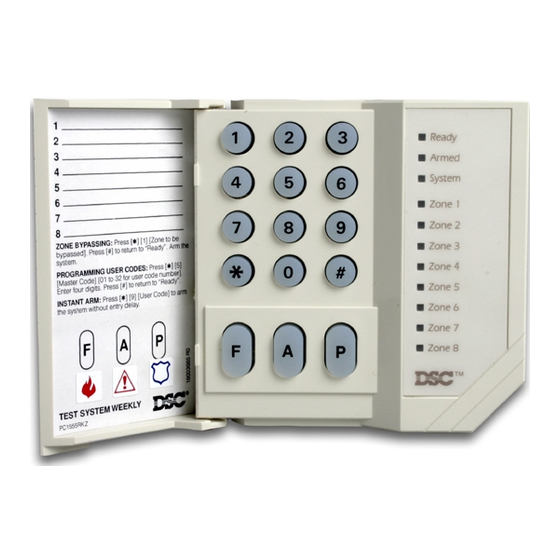
Page 5: Keypad Functions
The “Armed” light will flash to indicate that the The PC1500RK remote keypad provides complete information and system is armed without an entry delay. control of the PC1550 control panel. The control panel can be fully Disarming programmed from the PC1500RK keypad. The 6 zone lights provide Enter the premises through the designated entry-exit door. -
Page 6: Alarm Memory [ ]+[3]
(1234). The Master Code may be changed here if the user has been enabled to change the Master Code, or in section 6. Loss of Time on System Clock When the PC1550 is powered [21] by the installer. -
Page 7: Utility Output Command
[2] Set Auto-Arm Time entry delay. This command allows the user to remain at home and The PC1550 can be programmed to arm at the same time each day. have an instant alarm on the entry doors. At the selected Auto-Arm time, the bell will sound one short burst... -
Page 8: Programming
Programming The essential information which defines the operation of the control function ON or OFF; the zone light will turn ON or OFF to indicate the panel is stored in a section of the EEPROM memory which is state of the function.. All functions can be turned OFF at once by accessible using the Installer’s Programming code or via pressing [0]. -
Page 9: 2Nd Phone Number
Where a zero is required in the account code, enter HEX ‘A’ ( , 1, • Format Code [8], [9], [A], [B], [C] depending on ) to transmit 10 pulses which will be interpreted as a zero by the receiver type in section [23] monitoring station receiver. -
Page 10: Maintenance Alarms And Restorals
Transmission for operation of the [F], [A] and [P] keys will only take [3] Interior Home-Away Loop operates the same as the type [2] place if the appropriate sections in [09] are programmed with a loop with the following exception. If the system is armed and the reporting code. -
Page 11: 1St System Option Code
Section [11], Digit #2 Summary: [14] 3rd System Option Code [0] = Standard delay loop Use the same method of programming as section [12]. [1] = Instant loop ZONE [2] = Interior Loop LIGHT [3] = Interior... home / away loop ON = Access code required for bypass [4] = 24 hour... -
Page 12: Auxiliary Delay Loop Entry/Exit Times
Zone 2 = 20... Zone 6 = 60). The zero in the 2nd digit position each telephone number, enter one digit from the list below. See the tells the PC1550 not to send an extended round. HEX data programming section for details on how to enter digits ‘A’... -
Page 13: Programmable Output Options (Pgm Terminal)
Openings “B” i.e. B2 = opening by user 2 This option configures the system for use with the LINKS1000 • Closings “C” i.e. C4 = closing by user 4 Cellular Alarm Communicator. Refer to the LINKS Installation • Troubles “F” i.e. -
Page 14: 4Th System Option Code
See section [31], light 3. default. [34] 6th System Option Code NOTE: Panels returned to DSC with the installer’s lockout feature enabled and no other apparent problems will be subject to an Use the same programming method as in Section [12]. additional service charge. -
Page 15: For The Record
For The Record PC1550 Version 4.0 Customer ___________________________________________________________________________________________________ Address ___________________________________________________________________________________________________ ___________________________________________________________________________________________________ Phone ___________________________________________ Installation Date _____________________________________ CONTACTS: #1 Name ___________________________________________ Phone ______________________________________________ #2 Name ___________________________________________ Phone ______________________________________________ #3 Name ___________________________________________ Phone ______________________________________________ Installer’s Code ______________________________________ ZONES Zone Type Protected Area... -
Page 16: Programming Work Sheets
Programming Work sheets NOTE: In sections [01] to [10], do not enter data into sections that are not used. [01] 1st Phone Number Page 8 Enter [0] for the digit 0 in the phone number. Enter [ ] (HEX D) for additional dial tone detection between number digits, as in local PBX systems. - Page 17 PC1550 Version 4.0 [11] Zone Definitions Page 10 NOTE: When defining zones, assign delay zones first to zones 1,2,3..., then assign the other zone types to the remaining zones in any order desired. First Digit Second Digit Default 0 = Slow, Audible...
- Page 18 PC1550 Version 4.0 [15] Communication Variables Page 11 Default Maximum transmissions per burglary zone Enter digits from “01” to “99” for number of transmissions per zone during the period as defined in Section [12], 1st System Option Code, Zone Light 2. Note that “00” = unlimited transmissions per burglary zone. Fire zone always transmits.
- Page 19 PC1550 Version 4.0 [23] Communication Formats Page 12 It is necessary to program the format for both numbers, even if the second telephone number is not used. Default Default 1st Telephone Number 2nd Telephone Number Enter one HEX digit from [0] to [F] for each phone number from the following list:...
- Page 20 Number of Invalid Codes before lockout Lockout Duration (minutes) [90] Installer’s Lockout Enable Page 14 [91] Installer’s Lockout Disable Page 14 WARNING! Panels returned to DSC with the Installer’s Lockout enabled and no other apparent problems will be subject to an additional service charge!
- Page 21 PC1550 Control Panel Wiring Diagram Incorrect connections may result in fuse failure or improper operation. Inspect wiring and ensure connections are correct before applying power. Do not route any wiring over circuit boards. Maintain at least 1” (25.4mm) distance.
- Page 22 New Downloading Software Downloading Software DLS-1 Version 5.3C and later must be used to upload and download with the new PC1550 v4.0 Software. Do not attempt to perform downloading/uploading functions with the DLS-1 v5.2C or earlier software. ©...
-
Page 24: Limited Warranty
WARNING: Digital Security Controls Ltd. recommends that the entire system be completely tested on a regular basis. However, despite frequent testing, and due to, but not limited to, criminal tampering or electrical disruption, it is possible for this product to fail to perform as expected. This manual is for the PC1550 software version 4.0...
Need help?
Do you have a question about the PC1550 and is the answer not in the manual?
Questions and answers