Table of Contents
Advertisement
WARNING: This manual contains information on limitations regarding product use and function and information on the limitations
as to liability of the manufacturer. The entire manual should be carefully read.
PowerSeries Neo Alarm Controller
V1.1 Reference Manual
Models:
HS2016-4/HS2016/HS2032/HS2064/HS2128
Advertisement
Table of Contents

Subscribe to Our Youtube Channel
Related Manuals for DSC Neo


Summary of Contents for DSC Neo
- Page 1 PowerSeries Neo Alarm Controller V1.1 Reference Manual Models: HS2016-4/HS2016/HS2032/HS2064/HS2128 WARNING: This manual contains information on limitations regarding product use and function and information on the limitations as to liability of the manufacturer. The entire manual should be carefully read.
-
Page 2: Safety Instructions For Service Personnel
Safety Instructions for Service Personnel Warning: When using equipment connected to the telephone network, always follow the basic safety instructions provided with this product. Save these instructions for future reference. Inform the end-user of the safety precautions that must be observed when operating this equipment. - Page 3 used for installation of the alarm system and accessories, shall be insulated with PVC, TFE, PTFE, FEP, Neoprene or Polyamide. (a) The equipment enclosure must be secured to the building structure before operation. (b) Internal wiring must be routed in a manner that prevents: - Excessive strain or loosening of wire on terminal connections;...
-
Page 4: Table Of Contents
Contents Section 1: Introduction 1.1 About the System Section 2: Installation 2.1 Overview of Installation Process 2.2 Alarm Controller Installation 2.3 Wiring 2.4 Installing Modules Section 3: Configuration 3.1 Basic Configuration Steps 3.2 Using the Keypad 3.3 Enrollment 3.4 Working with Partitions 3.5 Trouble Indicators 3.6 Keypad Partition Setup 3.7 Alternate Communicator Setup... -
Page 5: Table Of Contents
6.12 Virtual Inputs 6.13 Schedule Programming 6.14 Audio Module Programming 6.15 Wireless Programming 6.16 Alternative Communicators 6.17 Keypad Programming 6.18 Template Programming 6.19 System Information and Testing 6.20 Module Programming 6.21 Testing 6.22 Battery Settings 6.23 Restoring Factory Defaults Section 7: Troubleshooting 7.1 Testing 7.2 Troubleshooting Appendix 1: Reporting Codes... -
Page 7: Section 1: Introduction
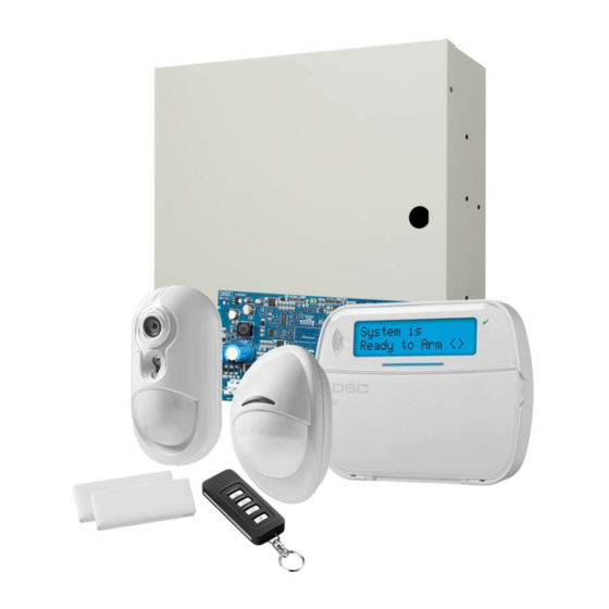
1.1 About the System The PowerSeries Neo alarm panel is a feature-rich, scalable alarm system designed for residential and light commercial use. The alarm panel supports both hardwired and wireless devices. This section lists the features of the alarm panel, avail- able models, and compatible devices. - Page 8 Section 1: Introduction User, partition, module, zone and system labels Programmable system loop response Keypad and panel software versions viewable through keypad Doorbell zone type Low battery PGM type 1.1.2 Available Models The following alarm controller models are available: HS2016-4 HS2016 HS2032 HS2064...
-
Page 9: Compatible Devices
Section 1: Introduction 1.1.3 Compatible Devices The following wireless devices and modules are compatible with this alarm controller. Note: On the table below and throughout this document, x in the model number represents the operating frequency of the device as follows: 9 (912-919 MHz), 8 (868MHz), 4 (433MHz). Note: Only models operating in the band 912-919 MHz are UL/ULC listed where indicated. - Page 10 Section 1: Introduction Hardwired Devices 2-wire smoke detector FSA-210y FSA-210yT y= A, B, or C FSA-210yS FSA-210yST A: ULC listed models FSA-210yR B: UL listed models FSA-210yRT C: European and Australian models FSA-210yRS FSA-210yRST 4-wire smoke detector FSA-410y FSA-410yT x= A, B, or C FSA-410yS FSA-410yST A: ULC listed models...
- Page 11 Section 1: Introduction Wireless PG outdoor siren PGx911 Wireless PG repeater PGx920 Wireless PG door/window contact PGx975 Wireless PG door/window contact w/ AUX PGx945 Central Station Receivers SG-System I, II, III, IV, 5 Enclosures The HS2128/HS2064/HS2032/HS2016 main board can be installed in the metal enclosures listed below: Tamper protection switches can be installed on all enclosures, including door opening protection and/or removal from the mounting position.
-
Page 12: Section 2: Installation
Section 2: Installation 2.1 Overview of Installation Process The steps below are provided to assist with the installation of the alarm system. Read over this section to get an overall understanding of the order of installation. Working from this plan can help reduce problems and reduce the overall time required for installation. -
Page 13: Wiring
Minimum 1/4” (6.4mm) separation must be maintained at all points between power limited and non-power lim- ited wiring and connections. 2.3.1 Terminal Descriptions The following terminals are available on the PowerSeries Neo alarm controller. Terminal Description BAT+, BAT- Battery terminals. Use to provide backup power and additional current when system demands exceed the power output of the transformer, such as when the system is in alarm. - Page 14 Section 2: Installation Figure 2-1 Wiring Routing (North America only) - 14 -...
- Page 15 Section 2: Installation Figure 2-2 Wiring Routing (EN50131 only) 2.3.3 Corbus Wiring The RED and BLK Corbus terminals are used to provide power while YEL and GRN are used for data communications. The 4 Corbus terminals of the alarm controller must be connected to the 4 Corbus terminals or wires of each module. The following conditions apply: Corbus should be run with minimum 22 gauge quad, two pair twisted preferred.
- Page 16 Section 2: Installation Note: Any module can be connected anywhere along the Corbus. Separate wire runs for keypads, zone expanders etc. are not necessary. Note: No module can be more than 1,000'/305m (in wire length) from the panel. Do not use shielded wire for Corbus wiring. Figure 2-3 Corbus Wiring Module (A) is wired correctly as it is within 1,000'/305m of the panel, in wire distance.
- Page 17 Section 2: Installation Alarm Controller Current Calculation Maximum (Standby or Alarm) AUX (700mA max. including PGMs 1-4) Corbus (700mA max.)*** PCLink+ (Alt. Com.:125mA) Total (must not exceed 700mA) *** See "Corbus Current Calculation Chart" on page 17. For UL, ULC and Commercial Listed applications, the total standby and alarm current cannot exceed 700mA. Table 2-2 Corbus Current Calculation Chart Item Current (mA)
-
Page 18: Installing Modules
Section 2: Installation *These units draw current from the Corbus to power devices external to the module. This current must be added to the total Corbus current. See manufacturer's specifications for the current draw of each device. ** For HSM2955 current draw refer to HSM2955 installation manual. Line Loss Voltage loss through wire resistance must be considered for all installations. - Page 19 Section 2: Installation Figure 2-4 HSM2108 Zone Expander Refer to the HSM2108 installation sheet for more information. 2.4.2 Output Expander The HSM2208 module is used to add up to 8 low-current programmable outputs to the alarm system. The 4-wire Corbus connection is used by the panel to communicate with the module. Connect the RED, BLK, YEL and GRN terminals to the Corbus terminals on the alarm panel.
-
Page 20: Power Supply Wiring
Section 2: Installation 2.4.4 Power Supply Wiring The HSM2300/2204 power supply/high-current output module provides up to 1.0A of additional current and can be used to add up to four programmable outputs (HSM2204 only) to the alarm system. The 4-wire Corbus connection provides communication between the module and alarm panel. Connect the RED, BLK, YEL and GRN terminals to the Corbus terminals on the alarm controller. -
Page 21: Zone Wiring
Section 2: Installation Figure 2-8 Keypad P/Z Terminals Note: When using end of line supervision, connect the zone according to one of the configurations outlined in "Zone Wiring" on page 21. End of line resistors must be placed on the device end of the loop, not at the keypad. Assigning Keypad Zones When using keypad zone inputs, each input used must be assigned a zone number in Installer Programming. - Page 22 Section 2: Installation Table 2-4 Burglary Zone Wiring Chart Wire Gauge Maximum Length to EOL Resistor (ft/meters) 3000 / 914 4900 / 1493 6200 / 1889 7800 / 2377 Figures are based on maximum wiring resistance of 100 Ω. Normally Closed Connect hardwired devices to any Z terminal and any Com terminal.
-
Page 23: Pgm Wiring
Section 2: Installation Double End of Line (DEOL) Resistors When double end-of-line (DEOL) resistors are installed at the end of a zone loop, the second resistor enables the panel to determine if the zone is in open, closed, tampered or faulted. Note: Any zone programmed for Fire or 24-hr Supervisory must be wired with a SEOL resistor regardless of the type of zone wiring supervision selected for the panel. -
Page 24: Bell Wiring
Section 2: Installation UL Compatibility ID For FSA-210B Series is: FS200 Note: For ULC listed installations, use FSA-210A and FSA-410A series. 2.4.10 Bell Wiring These terminals supply 700mA of current at 10.4 - 12.5VDC for commercial/ residential installations. To comply with NFPA 72 Temporal Three Pattern requirements, section [013] Opt [8] must be ON. - Page 25 FSA-410BS FSA-410BRT FSA-410BST FSA-410BRS Current ratings for DSC FSA-410 Series: 25mA - 90mA Fire Zone Wiring: 2-wire Smoke Detectors If PGM 2 is programmed for 2-wire smoke detector connection, the detectors must be wired according to the following dia- gram: Figure 2-16 2-Wire Smoke Detector Wiring Note: Additional 2-wire smoke detectors must be connected in parallel as shown above.
- Page 26 Section 2: Installation 2.4.13 CO Detector The following hardwired CO detector models can be used with PowerSeries Neo alarm controllers: Potter Model CO-12/24, UL File E321434 Quantum Model 12-24SIR, UL File E186246 NAPCO Model FW-CO12 or FW-CO1224, UL File E306780 System Sensor Model CO1224, UL File E307195 Note: For multiple unit connections, the leads between CO detectors must be broken.
- Page 27 Section 2: Installation 2.4.14 Ground Wiring Figure 2-18 Ground Installation Note: Using an insulated green wire (minimum 22AWG), connect the EGND terminal on the Corbus and the grounding wire from the building electrical installation to any of the available holes on the back or side of the metal cabinet. See the diagram attached to the cabinet for suggested GND point location and hardware recommendations.
- Page 28 Section 2: Installation Table 2-12 Standby Battery Guide Battery Size Desired Standby Time 700mA ------ ------ ------ 700mA 500mA 250mA ------ 14Ah 700mA 470mA ------ (use 2 x 7Ah batteries connected in parallel, UL/ULC installations only ) 18Ah ------ ------ ------ 300mA* 26Ah...
-
Page 29: Section 3: Configuration
"Testing the System" on page 36 3.2 Using the Keypad The PowerSeries Neo alarm panel is compatible with several different keypad types (see "Compatible Devices" on page 9); However, all keypads have certain basic functionality in common. -
Page 30: Enrollment
Section 3: Configuration 4 flashes - low battery trouble 5 flashes - AC trouble 6 flashes - AUX trouble 7 flashes - bell trouble 8 flashes - TLM trouble How to Enter Data Conventions Used In This Manual Brackets [ ] indicate numbers or symbols that must be entered on the keypad. e.g., [*][8][Installer Code][804] requires the following key entries: [*][8][5555][804] [*] initiates a special command. -
Page 31: Enroll Wireless Devices
Section 3: Configuration Module HS2016-4 HS2016 HS2032 HS2064 HS2128 Wireless Keypad: HS2LCDRF(P)4 HS2ICNRF(P)4 HS2LCDWF(P)(V)4 HS2TCHP Touchscreen Keypad HSM2300 Power Supply 1A HSM2204 4 High-current Output HSM2HOSTx Transceiver HSM2955 (not UL evaluated) Modules can be enrolled automatically or manually using section [902] of Installer programming. For instructions on enrolling modules, see "Module Programming"... -
Page 32: Working With Partitions
Section 3: Configuration Pre-Enrollment Pre-enrollment is a two step process. The first step requires entering each device ID ([804][001]-[716]). Every wireless device has an ID printed on the sticker attached to the device. The format is XXX-YYYY where: XXX identifies the type or model of the device YYYY is a short encrypted ID used by the system to identify the specific device Pre-enrollment can be done at a remote location and using DLS/SA. -
Page 33: Trouble Indicators
Section 3: Configuration 3.5 Trouble Indicators Both audible and visual trouble indications are available on all partitions. For more information, see "[*][2] Trouble Display" on page 44. Programming section [013] option 3 controls whether or not troubles are indicated when the alarm system is armed. 3.6 Keypad Partition Setup Keypads can be configured to control an individual partition or all partitions. -
Page 34: Factory Defaults
Section 3: Configuration 3.6.4 Bell/PGM Support PGMs must be assigned to one or more partitions. See section [007] for partition assignment. Note: Bell PGM type requires supervision and follows arming squawks by partition. 3.6.5 Communications Account codes are assigned to all system and partition events. For SIA communications, a single account code (programmed in section [310][000]) is used for all events. -
Page 35: Alternate Communicator Setup
Section 3: Configuration Hardware default is logged to the event buffer. Note: Hardware default is not available when installers lockout is enabled. 3.7 Alternate Communicator Setup The alternate communicator is an optional wireless or ethernet communications device that can be used as a backup to the PSTN connection or as a primary means of communication between the alarm panel and the central monitoring station. -
Page 36: Local Firmware Upgrade
Section 3: Configuration 3.7.6 Remote Firmware Upgrade Firmware upgrades can be automatically pushed to the alarm panel and modules from Connect 24 or DLS. A message is dis- played on LCD keypads indicating a firmware upgrade is available. On all keypads, the blue proximity tag bar flashes one second on - one second off. -
Page 37: Section 4: System Operation
[*][0] * - requiring an access code can be programmed in Section [015] For detailed arming/disarming instructions, see the PowerSeries Neo User Manual. 4.2 Partition vs. Global Keypad Keypads can be configured to control an individual partition or all partitions (see "Keypad Partition Setup " on page 33). -
Page 38: Labels
Section 4: System Operation In the following example, partition 1 is armed, partition 2 is disarmed and ready, partition 3 is disarmed and not ready, par- tition 4 is in alarm, partition 5 is indicating exit delay, partition 6 is in entry delay, partition 7 is in auto-arm pre-alert and par- tition 8 is not enabled. -
Page 39: Annunciation
Section 4: System Operation Fire alarm Fail to arm Alarm when armed CO alarm The maximum label size is 14 ASCII characters. See page 61 for more details. 4.3.6 Partition Command Output Labels This feature is used to program custom labels for command outputs. These labels are used with output activation events in the event buffer. - Page 40 Section 4: System Operation [06] [*][4] Chime On/Off [33] Bypass Recall [07] System Test [34] User Programming [*][5] [09] Night Arm [35] User Functions [*][6] [12] Global Stay Arm [37] Time & Date Program [13] Global Away Arm [39] Trouble Display [*][2] [14] Global Disarming [40] Alarm Memory [*][3] [16] Quick Exit...
- Page 41 Section 4: System Operation [12] Global Stay Arm This function arms all partitions assigned to the user in Stay mode, provided they are ready to arm. If a partition is not ready, the system cannot be armed. An access code is required with this option. [13] Global Away Arm This function arms all partitions assigned to the user in Away mode, provided they are ready to arm.
-
Page 42: Language Selection
Section 4: System Operation [39] Trouble Display This function puts the keypad in trouble display mode and is equivalent to pressing [*][2]. This function only works while the system is disarmed. This function key requires a code if section [023] option 5 is enabled. [40] Alarm Memory This function puts the keypad in alarm memory display mode and is equivalent to pressing [*][3]. - Page 43 Section 4: System Operation [*][9] No entry arming [*][0] Quick arm/Exit While in a [*] command menu, use the [*] key to select an option and the [#] key to exit to the previous screen. On an LCD keypad, use the scroll keys to view options. 4.7.1 [*][1] Bypass or Stay/Away/Night Zones The [*][1] command functions differently depending on whether the system is armed or disarmed.
-
Page 44: Trouble Display
Section 4: System Operation Bypass Recall Press [*] while in this menu to bypass the same group of zones that were bypassed the last time the partition was armed. Clear Bypasses Press [*] to clear all bypasses. Shortcuts from the [*][1] base menu: 991 = bypass group 995 = program group 1 998 = bypass open zones... - Page 45 Section 4: System Operation Trouble 02 – Battery Trouble: [01] Panel Low Battery Trouble: The battery voltage (under load) is below 11.5V. Restores at 12.5V. [02] Panel No Battery: No battery connected to alarm controller. [04] HSM2204 01 - 04 Low Battery: An HSM2204 has a battery voltage less than 11.5V. [05] HSM2204 01 - 04 No Battery: No battery connected to HSM2204.
- Page 46 Section 4: System Operation Trouble 08 – RF Delinquency Trouble: [01] Zone 001 - 128 RF Delinquency: No response from a wireless zone for 13 minutes. This trouble prevents arming until acknowledged or cleared using [*][2]. [02] Keypad 01 - 16 RF Delinquency: No response from a wireless keypad for 13 minutes. [03] Siren 01 - 16 RF Delinquency: No response from a wireless siren for 13 minutes.
- Page 47 Section 4: System Operation IMPORTANT! Ensure you have the following information available before contacting Customer Support : Alarm controller type and version, (e.g., HSM2064 1.0): Note: Version number can be accessed by entering [*][Installer Code][900] on any LCD keypad. This information is also loc- ated on a sticker on the printed circuit board.
- Page 48 Section 4: System Operation Access Code Types The alarm system provides the following access code types: Code Add User Delete User Disarm [*][5] [*][6] [*][8] Installer Yes + Master All* Yes No Maintenance User No** No Supervisor All but Master All but Master Yes No Duress...
- Page 49 Section 4: System Operation Duress Codes - Access Codes [02] to [95] Duress codes function the same as user access codes, except they transmit a duress reporting code when used to perform any function on the system. Duress codes cannot be used to access [*][5], [*][6] or [*][8] menus. Duress codes are created by the master user or supervisor users.
- Page 50 Section 4: System Operation 7 – Bell Squawk When this option is assigned, the main bell squawks when the alarm system is away armed. For example, use the arm/dis- arm bell squawk attribute to have wireless key access codes squawk the bell, while other codes are silent. To do this, enable this attribute on all access codes associated with wireless keys.
- Page 51 Section 4: System Operation To increase authentication flexibility, user access can be achieved by entering a valid user code or by swiping a proximity tag. Alternatively, users can be required to enter a valid access code and present a proximity tag. See "[040] User Authentic- ation"...
- Page 52 Section 4: System Operation Time and Date Use this section to program the alarm system clock. Menu: [*][6][Master Code] > Time and Date Keypad: [*][6][Master Code] + 01 Enter time and date using the following format: (HH:MM); (MM-DD-YY). Valid time entries are 00-23 hours, 00-59 minutes. Valid date entries are 01-12 months, 01-31 days.
- Page 53 Section 4: System Operation User Call-up Menu: [*][6][Master Code] > User Call-up Keypad: [*][6][Master Code] + 06 When selected, this function makes a single attempt to call the downloading computer. The downloading computer must be waiting for the call before downloading can be performed. Only one call-up is attempted. If a DLS phone number is not pro- grammed, the alarm panel attempts to reach the DLS computer via IP connection.
- Page 54 Section 4: System Operation Keypad: [*][6][Master Code] + 13 This function is used to change the contrast level of keypad displays. Use the scroll keys to increase and decrease contrast or enter a value from 00 to 15. Selecting 00 turns off keypad contrast. Buzzer Control Menu: [*][6][Master Code] >...
-
Page 55: Sms Command And Control
Section 4: System Operation Other programming options that may affect this user function: See "[990] Installer Lockout Enable/Disable" on page 121 4.7.9 [*][9] No-Entry Arming This function is used to arm the alarm system while occupants are on the premises. Pressing [*][9] and then keying in an access code arms the panel without an entry delay on delay type zones and bypasses stay/away and night type zones. -
Page 56: Visual Verification
Section 4: System Operation e.g., Stay Arm partition 1 1234 Once the command is received and executed by the alarm system, the user receives a confirmation text message. Note: Do not use Away Arm if Push to Set [001][072] or Final Door Set [001][016] zones are programmed. 4.9 Visual Verification This feature enables the central station operator to view captured images of the premises in the event of an alarm event. -
Page 57: Section 5: Programming
DLS downloading. See Template Programming below for details. DLS pro- Download and apply programming using DLS 5 v1.3 for Neo v1.0 For local DLS, use a PC-Link cable and gramming panels and DLS 5 v1.4+ for Neo v1.0 and v1.1 products. -
Page 58: Dls Programming
001 and 255. E.g., Press 020 for a delay of 20 seconds. See "[005] System Times" on page 70 for additional details. The CP-01 models of the Neo panel will not accept a value less than 30 seconds. - Page 59 Section 5: Programming 3. Select an option to view or change its programming. All programming options are numbered and can be accessed by navigating through the menu (LCD) or by keying in the pro- gram section number. For toggle options, the name of the option is displayed (LCD) or LEDs 1-8 are illuminated (LED and ICON).
- Page 60 Section 5: Programming For programming sections with toggle options, press the corresponding number on the keypad to turn the option on or off. The display changes accordingly. Sections requiring data input, such as phone numbers, display the full data in fields up to 32 characters long. To input data, use the scroll keys to select a character then press the keypad button corresponding to the number/letter required.
-
Page 61: Programming Descriptions
Section 5: Programming 5.3 Programming Descriptions This section provides descriptions of all alarm controller options programmable by the installer. 5.3.1 Adding Labels [000] Label Programming Zone and other labels on the alarm system can be customized. Program labels locally or download/upload using DLS. Local label programming is done via a system keypad, as described below. - Page 62 Section 5: Programming Press To Select/Display [SELECT] [ESCAPE] [SPACE] [A], [B], [C], [1] [D], [E], [F], [2] [G], [H], [I], [3] [J], [K], [L], [4] [M], [N], [O], [5] [P], [Q], [R], [6] [S], [T], [U], [7] [V], [W], [X], [8] [Y], [Z], [9], [0] Zone Label Options To access zone label options such as using ASCII characters, changing letter case and clearing the display, press [*] while...
- Page 63 Section 5: Programming [051] Zone Tamper Label This label is displayed when a zone is tampered. The maximum label size is 14 x 1 ASCII characters. [052] Zone Fault Label This label is displayed when a zone is in fault. The maximum label size is 14 x 1 ASCII characters. [064] CO Alarm Message Use this section to program a custom label that is displayed on keypads during a carbon monoxide alarm.
-
Page 64: Zone Setup
Section 5: Programming [808] HSM2955 Label Use this section to create a custom label for the 2-way wireless transceiver. [809][001]-[004] HS2300 Power Supply Label Use this section to create custom labels for power supplies on the system. Select 001-004 for power supply 1-4. [810][001]-[004] HS2204 High-Current Output Supply Label Use this section to create custom labels for high-current output supplies on the system. - Page 65 Section 5: Programming Delayed 24-Hour Fire – This zone is used with smoke detectors and functions similar to the standard fire zone, except the communicator delays the alarm memory and transmission by 30 seconds. If the alarm is acknowledged by pressing any key, the siren is silenced and the transmission aborted.
- Page 66 Section 5: Programming If a wireless key is used to away arm the system, the door must still be opened then closed to complete the arming sequence. The indoor siren will activate until the exit delay has expired. 24-Hour Burglary –...
- Page 67 Section 5: Programming 24-Hour Heat – Instant alarm when activated, audible alarm at default. Note: For use with normally closed contacts. 24-Hour Medical – Instant alarm when activated, audible alarm at default. 24-Hour Emergency – Instant alarm when activated, audible alarm at default. 24-Hour Sprinkler –...
- Page 68 Section 5: Programming With an audible alarm active, using the keyswitch when disarmed is the same as entering an access code at the keypad. Activating this zone type during the first 30 seconds of a delayed fire alarm is the same as pressing a key at the keypad (the 90 second delay starts).
- Page 69 Section 5: Programming Bypass Enabled – ON: The zone can be manually bypassed. OFF: The zone cannot be bypassed. Force Arm – ON: The system can be armed with the zone open. The zone is temporarily bypassed and, when secured, is monitored by the system.
-
Page 70: System Times
Section 5: Programming 5.3.3 System Times This section describes how to program various timers applicable to the entire alarm system. [005] System Times This is the base menu used by installers to program timers, including system area [000], partition timers [001]-[008], and day- light saving time [901]/[902]. -
Page 71: Access Codes
Section 5: Programming Settle Delay: This timer enables a programmable, short duration bypass of all zones on the partition at the time of arming. It allows motion detectors to restore when the system is armed to help prevent false alarms. The typical value for this timer is 5 seconds, but can be increased if false alarms persist. - Page 72 Section 5: Programming 5.3.5 [007] - [008] PGM Configuration This section describes how to set up and configure programmable outputs. PGMs are used to send electrical current to external devices such as lights and sirens, usually when an alarm event occurs. The alarm controller provides up to three 50mA PGMs and one 300mA PGM.
- Page 73 Section 5: Programming fire alarm cadence CO alarm cadence other alarm cadences The main siren still activates for all alarms. 102 – Delayed Fire and Burglary This output type operates the same as the Burglary and Fire Bell Follower (PGM type 01), but does not activate until the trans- mission delay time expires.
- Page 74 Section 5: Programming 116 – Away Armed Status This PGM switches on when the system is armed with stay/away zones activated. If the system is armed with the stay/away zones always active, then the away output is active. 117 – Stay Armed Status This PGM output activates if the system is armed with the stay/away zones bypassed.
- Page 75 Section 5: Programming 146 – TLM and Alarm This output activates when a telephone line fault condition is present AND an alarm occurs. The output remains active until an access code is entered to disarm or the TLM trouble is restored. The output activates for all audible and silent alarms (except duress) if a TLM trouble is present.
- Page 76 Section 5: Programming 156 – Latched System Event (Strobe) This output can be used to notify the home owner, before they enter the premises, that an alarm has occurred. This output can be programmed to activate when any of the following alarms occur on the system: Burglary (Delay, Instant, Interior, Stay/Away and 24-Hour Burglary Zones) Fire (Fire Key, Fire Zones) Panic (Panic Key and Panic Zones)
- Page 77 Section 5: Programming 184 – Open After Alarm This output activates when the system has been disarmed after an alarm. It deactivates when a valid user code is entered or when the PGM Output timer expires. 200 – Zone Follower - PGM By Zone This option allows the PGM to activate when the assigned zone is opened and deactivate when the zone is restored or, if pro- grammed, when a valid access code is entered.
- Page 78 Section 5: Programming OFF: Squawks do not activate the main siren. [001]-[164] PGM 001-164 Attributes The following PGM attributes can be assigned to a PGM. Each attribute has various toggle options, depending on the PGM type selected (section [009]). 101 – Fire and Burglary 01 –...
- Page 79 Section 5: Programming 14 – Auto-Arm Pre-Alert ON: activates when auto-arming pre-alert begins. OFF: does not activate when auto-arming pre-alert begins. 114 – Ready To Arm 01 – True Output/Inverted ON: deactivated during normal operation. Activated when triggered. OFF: active during normal operation. Deactivated when triggered. 115 –...
- Page 80 Section 5: Programming 147 – Kissoff Output 01 – True Output/Inverted ON: deactivated during normal operation. Activated when triggered. OFF: active during normal operation. Deactivated when triggered. 148 – Ground Start 01 – True Output/Inverted ON: deactivated during normal operation. Activated when triggered. OFF: active during normal operation.
- Page 81 Section 5: Programming 14 – Hold Up verified ON: activates when a verified holdup event is detected. OFF: does not activate when a verified holdup event is detected. 155 – System Trouble 01 – True Output/Inverted ON: deactivated during normal operation, activated when triggered. OFF: activated during normal operation, deactivated when triggered.
- Page 82 Section 5: Programming zone 001 – 128 keypad 01 – 16 siren 01 – 16 repeater 01 – 08 OFF – does not activate if a device tamper condition is present. 12 – RF Delinquency ON: activates if any of the following RF delinquency troubles is detected: zone 001 –...
- Page 83 Section 5: Programming OFF: activated during normal operation. Deactivated when triggered. 02 – Timed Output / Latched Output ON: output remains active until the PGM output timer expires. OFF: output remains active until an access code has been entered. 04 – Fire Alarm ON: activates with fire alarm, [F] key, fire zones, 2-wire smoke.
- Page 84 Section 5: Programming OFF: does not activate when any module tamper condition occurs. 10 – Zone Tampers ON: activates when any zone tamper condition occurs. OFF: does not activate when zone tamper conditions occur. 161 – DC Trouble 01 – True Output/Inverted ON: deactivated during normal operation.
- Page 85 Section 5: Programming 02 – Timed Output ON: output remains active until the PGM output timer expires. OFF: output remains active until an access code has been entered. 09-16 – Zone Terminals 1-8 ON: zones associated with terminals 1-8 are enabled for zone follower operation. OFF: zones are not enabled for zone follower operation.
-
Page 86: System Options
Section 5: Programming 5.3.10 System Options [013] System Option 1 1 – NC Loop/EOL ON: All zones are wired as normally closed circuits with returns connected to a COM terminal. The end-of-line resistor is not required. An alarm is generated when the circuit is opened. OFF: All zones must be wired with an end-of-line resistor configuration, determined by option 2 below. - Page 87 Section 5: Programming When the system is disarmed, the siren emits a series of three squawk pairs to indicate alarms in memory. OFF: The siren does not squawk when arming or disarming. Note: For UL/ULC, must be enabled if wireless keys are used with the alarm system. 2 –...
- Page 88 Section 5: Programming OFF: When the system is armed, users can not perform a quick exit using [*][0]. 4 – Quick Arming /Function Key ON: [*][0] arming and Stay/Away function keys may be used to arm the system without the entry of a valid access code. OFF: [*][0] arming is not permitted.
- Page 89 Section 5: Programming 5 – Keypad Backlighting ON: All keypads on the system have backlighting on at all times. OFF: All keypads on the system have backlighting off. 6 – Power Save Mode ON: If AC power fails, all keypad lights including backlighting are shut OFF. The keypad lights come back ON after a keypress, entry delay, audible alarm or keypad buzzer condition (except door chime).
- Page 90 Section 5: Programming Note: If the Auto-arm toggle option is disabled, the Auto-arm Pre-alert still occurs when a time is programmed for that day (if enabled) and the event is logged and communicated. This option does not directly affect the functionality of Auto-arm. If Late to Close is enabled and Auto-arming is not, LCD keypads display “System Arming in Progress”...
- Page 91 Section 5: Programming [019] System Option 7 1 – Audible Wireless Device Fault ON: If a wireless zone fault occurs while armed, the siren sounds for the duration of Bell Time Out. This option only affects zone definitions that are considered armed. The following zone types do not generate an alarm when faulted while stay armed: interior stay away zone, delay stay away zone, instant stay away zone, night zone.
- Page 92 Section 5: Programming This feature is only active when the partition is armed. OFF: Burglary alarms that occur during entry delay activate the siren and are communicated immediately. Two exceptions are if the bell delay timer is programmed and if transmission delay is enabled for the zone in alarm. In both cases, the alarm follows the timer.
- Page 93 Section 5: Programming Tampers on the alarm system, modules and zones Corbus troubles AC troubles on the alarm system and modules Battery troubles on the alarm system, modules and zones Transmission troubles (FTC, TLM, GPRS, Ethernet) Bell troubles The alarm system can still be armed if troubles are overridden. To perform a trouble override, while in the Trouble Menu ([*] [2]), scroll right or left and press [*] when Trouble Acknowledgment is displayed on the keypad.
- Page 94 Section 5: Programming 8 – Audible Exit Delay for Stay Arming ON: When the system is armed in Stay mode the exit delay is sounded by 1 beep every 3 seconds. OFF: When the system is armed in Stay mode the exit delay is silent. [022] System Option 10 1 –...
- Page 95 Section 5: Programming Note: This option applies to the Sequential Detection feature only. 4 – Access Code Required for [*][1] ON: When using the [*][1] Bypass Zones command, an access code must be input before zones are bypassed. OFF: An access code is not required to bypass zones using [*][1]. 5 –...
- Page 96 Section 5: Programming 6 – Not Used 7 – Not Used 8 – DLS Disconnect ON: All events except Periodic Test Transmission, Periodic Test with Trouble, and System Test are considered priority events. If DLS is active when an event occurs, the alarm system immediately terminates the connection in order to com- municate the new events.
-
Page 97: Partition Setup
Section 5: Programming OFF: If a Failure to Communicate trouble is generated while the alarm system is armed, the siren does not activate but the keypad buzzer emits trouble beeps until a key is pressed. [040] User Authentication This feature enables the installer or master user to select one of two user authentication methods: 01 –... - Page 98 Section 5: Programming Note: If entry delay is active at auto-disarm time, the system does not disarm. A valid disarming procedure is required by the user who initiated the entry delay. [003] – Partition Auto-Disarming Holiday Schedules Use this section to select a holiday schedule group. See "[711]-[714] Holiday Schedules"...
- Page 99 Section 5: Programming [201]-[208] Partition Zone Assignment Zones can be assigned to any partition. Global zones are zones assigned to more than one partition. A global zone is only armed when all assigned partitions are armed. The zone is disarmed when any of the assigned partitions is disarmed. By default, zones 1 through 8 are assigned to partition 1.
- Page 100 Section 5: Programming [004] The phone number used to communicate with receiver 4 All telephone numbers can be a maximum of 32 digits. Hexadecimal digits may be included to perform the following func- tions: HEX B ([*] [2] [*]) - to dial "*" HEX C ([*] [3] [*]) - to dial "#"...
- Page 101 Section 5: Programming 7 – Burglary Not Verified When using Cross Zoning, this reporting code is sent if the cross zone timer is initiated by the first cross zone alarm, but is not verified by a second alarm before the timer expires. 8 –...
- Page 102 Section 5: Programming 2 – Automatic Disarm This reporting code is transmitted when a partition is automatically disarmed when a scheduled time of day is reached. 3 – Auto Arm Cancellation/Postpone This reporting code is transmitted when the automatic arm sequence is canceled during a pre-alert and uses the Opening and Closing call direction group.
- Page 103 Section 5: Programming [305] Panel Events 5 3/4 – PGM 2 2-Wire Trouble/Restore This reporting code is transmitted when a trouble condition on PGM 2, configured as two-wire smoke, occurs or is restored. This reporting code is sent to the System Maintenance call direction group. [311] Maintenance Events 1 1/2 –...
- Page 104 Section 5: Programming 3 – Firmware Update Fail Sent after an unsuccessful remote firmware update. [314] Maintenance Events 4 1/2 – Gas Trouble/Restore Sent when a trouble occurs or is restored on a wireless gas detector. 3/4 – Heat Trouble/Restore Sent when a heat trouble occurs or is restored on a wireless temperature detector.
- Page 105 Section 5: Programming [354] Alternate Communicator 4 Receiver 1 to 4 Trouble and Restore Sent when the alternate communicator detects a trouble or restore condition on receiver 1-4. 1/2 – Receiver 1 Trouble/Restore 3/4 – Receiver 2 Trouble/Restore 5/6 – Receiver 3 Trouble/Restore 7/8 –...
- Page 106 Section 5: Programming 5 – System Test Sent when a manual system test is performed ([*][6][Master Code][04]). 5.3.13 System Communications The programming options in this section are used to configure communications between the alarm system and the central station. [309] System Call Direction Use this programming option to select the central station receivers that system events are communicated to.
- Page 107 Section 5: Programming [04] Receiver 4 [002] Tampers (Including System Tampers)/ Restore These options control which receiver paths are enabled for Partition 1-8 Tamper and Restore event reporting codes. To assign an event to a receiver, select one of the following options: [01] Receiver 1 [02] Receiver 2 [03] Receiver 3...
- Page 108 Section 5: Programming The delay is for zones which have the Transmission Delay attribute enabled. Valid entries are from 000 to 255 seconds (0- 45 seconds for CP-01). Each partition shares the same active timer. If the delay is already active due to an alarm on a dif- ferent partition, any new activity on another partition does not restart the communications delay timer.
- Page 109 Section 5: Programming [013] – Delay Between Force Attempts This programming option is used to set the length of time the alarm system waits between the first dialing attempt and the force dial attempt. Valid Entries are 001-255 seconds. Default is 020. [014] –...
- Page 110 Section 5: Programming Receiver 4 backs up Receiver 3 This continues until communication is successful or the sequence has been repeated 5 times (depending on the number of maximum dialing attempts). If all 5 attempts fail, an FTC trouble for the primary phone number is logged. All backup receivers automatically use the same call directions and format as the primary receiver.
- Page 111 Section 5: Programming 7. FTC'ed events OFF: Events are communicated in the order they occur. Note: Must be ON for ULC commercial fire monitoring listed installations. [382] Communicator Option 3 1 – Not Used 2 – Walk Test Communications ON: Zone alarms that occur during Walk Test are communicated if programmed to do so. OFF: Zone alarms during Walk Test are not communicated.
- Page 112 Section 5: Programming 6 – Not used [384] Communicator Backup Options 2 – Receiver 2 Backup Option ON: Receiver 2 backs up Receiver 1. Receiver 2 is only used if an FTC event is detected on Receiver 1. Receiver 2 uses the same format programmed for Receiver 1. OFF: Receiver 2 is independent and will communicate if a number and format are programmed.
- Page 113 Section 5: Programming [401] DLS/SA Options 1 – Double Call ON: Calls for downloading or SA are answered if a successful double call routine is detected. Have the downloading com- puter call the system and let the telephone line ring once or twice. After 1 or 2 rings, hang up. If called back within the dur- ation of the double call timer (section [405]), the alarm system answers on the first ring.
- Page 114 Section 5: Programming [405] PSTN Double Call Timer Use this section to program the amount of time that can elapse between the first and second call when using Double Call downloading. Valid entries are 001 to 255 (seconds). [406] PSTN Number of Rings to Answer On The value in this section determines how many rings are required in order to establish a DLS connection.
- Page 115 Section 5: Programming 5.3.15 Virtual Inputs When using an alternate communicator, virtual zones can be mapped to configured system zones. [560][001]-[032] Assign corresponding 3 digit zone number to virtual input and then the virtual input can be controlled by an alternate com- municator.
-
Page 116: Wireless Programming
Section 5: Programming 5.3.18 Wireless Programming [804] Wireless Programming This programming section is used to enroll, program and delete wireless devices. Note that the HSM2HOSTx wireless trans- ceiver or RF model keypad must be installed in order to enroll wireless devices. [000] –... -
Page 117: Module Programming
Section 5: Programming Central Station Account Code: The account code used in programming section [310]. This is a 4 or 6-digit entry. Partition Account Code: Used to identify partition-specific events. All 4 digits must be entered in order to complete the entry. - Page 118 Section 5: Programming [000] – Auto Enroll Modules When this mode is selected, the alarm system automatically enrolls all modules connected to the Corbus. The total number of modules currently enrolled are displayed on the keypad. Enter sub-section [000] to begin auto enrollment of all new modules. The auto enroll screen will show the following: KP = Number of keypad type modules IO = Number of zone and output type modules M = Number of other type modules...
- Page 119 Neo 2x16 LCD wirefree keypad HS2TCHWF Neo Touchscreen wirefree Keypad HS2LCDWFP Neo 2x16 LCD wirefree keypad with Prox HS2LCDWFPV Neo 2x16 LCD wirefree keypad with Prox and Voice HSM2955 Neo Audio alarm verification module HSM2955R Neo Audio alarm verification module with Recording 5.3.21 Testing...
- Page 120 Section 5: Programming [001]-[128] Placement Test Zones 1-128 Test wireless devices individually by zone (LCD keypads only). [521]-[528] Placement Test Repeaters 1-8 Test each enrolled wireless repeater (LCD keypads only). [551]-[566] Placement Test Sirens 1-16 Test each enrolled wireless siren (LCD keypads only). [601]-[632] Placement Test Wireless keys 1-32 Test individual wireless keys.
- Page 121 [989][installer code][989] or [*]. Note: Feature is only available for models of NEO. [990] Installer Lockout Enable/Disable When this option is enabled, an installer can not perform a hardware default; attempts to do so are logged to the event buf- fer.
-
Page 122: Section 6: Programming Worksheets
Section 6: Programming Worksheets Note: listed options are required for EN 50131 Compliant Installations. 6.1 Label Programming [000] Label Programming Description on page 61 [000] – Language Selection (2-digit decimal; Default: 01) 01 – English 06 – Dutch 11 – Swedish 16 –... - Page 123 Section 6: Programming Worksheets 079: 080: 081: 082: 083: 084: 085: 086: 087: 088: 089: 090: 091: 092: 093: 094: 095: 096: 097: 098: 099: 100: 101: 102: 103: 104: 105: 106: 107: 108: 109: 110: 111: 112: 113: 114: 115: 116: 117:...
- Page 124 Section 6: Programming Worksheets 202 – Partition 2 Command Output 001 – Partition 2 Command Output 1: Labels (2 X 14 ASCII) 002 – Partition 2 Command Output 2: 003 – Partition 2 Command Output 3: 004 – Partition 2 Command Output 4: 203 –...
- Page 125 Section 6: Programming Worksheets 001 – Keypad 1 Label: 009 – Keypad 9 Label: 002 – Keypad 2 Label: 010 – Keypad 10 Label: 003 – Keypad 3 Label: 011 – Keypad 11 Label: 004 – Keypad 4 Label: 012 – Keypad 12 Label: 005 –...
- Page 126 Section 6: Programming Worksheets [000] 815 – Alt. Comm Label: (1 X 14 ASCII) Description on page 64 [000] 820 – Siren Labels 001– Siren 1 Label: 009– Siren 9 Label: 002– Siren 2 Label: 010– Siren 10 Label: 003– Siren 3 Label: 011–...
-
Page 127: Zone Setup
Section 6: Programming Worksheets 6.2 Zone Setup [001] [001 - 128] Zone Type Available Zone Types Default = 000 Description on page 64 * Not UL evaluated 000 – Null Zone 018 – 24-Hour Bell/Buzzer 051 – 24-Hour Latching Tamper 001 –... - Page 128 Section 6: Programming Worksheets 6.2.1 Zone Attribute Defaults (Description on page 68) Zone Attributes 1 – Bell 5 –Force Arm 9 – Normally Closed EOL 13 - Zone 2-way Audio Audible Activation 6 – Swinger Shutdown 10 – Single EOL 2 –...
- Page 129 Section 6: Programming Worksheets 017 24-Hour CP-01 CP-01 Burglary 018 24-Hour CP-01 Bell/Buzzer 023 24-Hour CP-01 Supervisory 024 24- Hour CP-01 CP-01 Supervisory Buzzer 025 Auto Verify Fire 027 Fire Supervisory 040 24-Hour Gas CP-01 CP-01 041 24-Hour CO 042 24-Hour CP-01 CP-01 Holdup...
-
Page 130: System Times
Section 6: Programming Worksheets 057 24 Hour Low CP-01 CP-01 Temperature 060 24- Hr Non- CP-01 CP-01 Latching Tamper 066 Momentary Keyswitch Arm 067 Maintained Keyswitch Arm 068 Momentary Keyswitch Disarm 069 Maintained Keyswitch Disarm 071 Door Bell 072 Push to Set 6.3 System Times [005] System Times Description on page 70... - Page 131 Section 6: Programming Worksheets See partition 1 for defaults Entry Delay 2: Exit Delay: Settle Delay: 004 – Partition 4 Timer Entry Delay 1: See partition 1 for defaults Entry Delay 2: Exit Delay: Settle Delay: 005 – Partition 5 Timer Entry Delay 1: See partition 1 for defaults Entry Delay 2:...
-
Page 132: Access Codes
Section 6: Programming Worksheets Week (Default : 005): Day (Default : 000): Hour (Default : 001): Increment (Default : 001): 6.4 Access Codes [006] Installer-Defined Codes 001 – Installer Code (Default:555555): (4/6-Digit Decimal) 002 – Master Code (Default:123456): Description on page 71 003 –... - Page 133 Section 6: Programming Worksheets [008] [000 - 164] PGM Timer Programming 041 – PGM 41: 042 – PGM 42: 043 – PGM 43: 044 – PGM 44: 045 – PGM 45: 046 – PGM 46: 047 – PGM 47: 048 – PGM 48: 049 –...
- Page 134 Section 6: Programming Worksheets [009] [001] - [164] PGM Types 100 – Null PGM 122 – Command Output 2 157 – System Tamper 207 – Follower-Zones 49- 101 – Burg and Fire Bell 123 – Command Output 3 161 – DC Trouble 208 –...
- Page 135 Section 6: Programming Worksheets [009] [001] - [164] PGM Types 045 – PGM 45: 046 – PGM 46: 047 – PGM 47: 048 – PGM 48: 049 – PGM 49: 050 – PGM 50: 051 – PGM 51: 052 – PGM 52: 053 –...
- Page 136 Section 6: Programming Worksheets [010] [000 - 164] PGM Attributes R 01 – Fire Alarm [000] – Main Bell Mask R 02 – CO Alarm R 03 – Burglary Alarm Description on page 77 R 04 – Flood Alarm R 05 – Bell Squawks 001-164 PGM Attributes PGM 1-164: 100 –...
- Page 137 Section 6: Programming Worksheets [010] [000 - 164] PGM Attributes 133 - Burglary Verified R 01 – True Output R 01 – True Output 146 – TLM And Alarm R 01 – True Output 147 – Kissoff Output 148 – Ground Start R 01 –...
- Page 138 Section 6: Programming Worksheets [010] [000 - 164] PGM Attributes 156 – Latched System Event R 01 – True Output o 02 – Timed Output R 04 – Fire Alarm R 05 – Panic Alarm R 06 – Burglary Alarm R 07 –...
- Page 139 Section 6: Programming Worksheets [010] [000 - 164] PGM Attributes 201 Zone Follower Zones 1-8 R 01 – True Output o 02 – Timed Output 202 Zone Follower Zones 9- R 09 – Zone Terminal 1 203 Zone Follower Zones 17- R 10 –...
- Page 140 Section 6: Programming Worksheets [010] PGM Attribute Assignment: 037 – PGM 37: 038 – PGM 38: 039 – PGM 39: 040 – PGM 40: 041 – PGM 41: 042 – PGM 42: 043 – PGM 43: 044 – PGM 44: 045 –...
- Page 141 Section 6: Programming Worksheets [011] PGM Config. Options Description on page 85 Zone Follower by Zone Prox. Used Schedule (000-128; Default 000) (000-095; Default 000) (000-004; Default 000) Alarm Panel 001 PGM 1 002 PGM 2 003 PGM 3 004 PGM 4 HSM2204 #1 005 PGM 5 006 PGM 6...
- Page 142 Section 6: Programming Worksheets [011] PGM Config. Options Description on page 85 Zone Follower by Zone Prox. Used Schedule (000-128; Default 000) (000-095; Default 000) (000-004; Default 000) HSM2208 #3 053 PGM 53 054 PGM 54 055 PGM 55 056 PGM 56 057 PGM 57 058 PGM 58 059 PGM 59...
- Page 143 Section 6: Programming Worksheets [011] PGM Config. Options Description on page 85 Zone Follower by Zone Prox. Used Schedule (000-128; Default 000) (000-095; Default 000) (000-004; Default 000) 089 PGM 89 090 PGM 90 091 PGM 91 092 PGM 92 HSM2208 #8 093 PGM 93 094 PGM 94...
- Page 144 Section 6: Programming Worksheets [011] PGM Config. Options Description on page 85 Zone Follower by Zone Prox. Used Schedule (000-128; Default 000) (000-095; Default 000) (000-004; Default 000) HSM2208 #12 125 PGM 125 126 PGM 126 127 PGM 127 128 PGM 128 129 PGM 129 130 PGM 130 131 PGM 131...
-
Page 145: System Lockout
Section 6: Programming Worksheets [011] PGM Config. Options Description on page 85 Zone Follower by Zone Prox. Used Schedule (000-128; Default 000) (000-095; Default 000) (000-004; Default 000) 161 PGM 161 162 PGM 162 163 PGM 163 164 PGM 164 6.6 System Lockout [012] System Lockout (3-Digit Decimal) - Page 146 Section 6: Programming Worksheets o 4 – Bell Squawk on Entry o 5 – Bell Squawk on Trouble o 6 – Not Used o 7 – Exit Delay Termination o 8 – Fire Bell Continues [015] System Options 3 Description on page 87 R 1 –...
- Page 147 Section 6: Programming Worksheets o 7 – Not Used o 8 – Bell Squawk on Away Arm/Disarm [018] System Options 6 Description on page 90 o 1 – Test Transmission Exception o 2 – Real-Time Bypass Reporting o 3 – Not Used o 4 –...
- Page 148 Section 6: Programming Worksheets R 8 – Troubles Inhibits Arming [021] System Options 9 Description on page 93 For systems compliant with EN50131-1 and EN50131-3, option [021] bit 2 “Keypad blanking while armed” must be o 1 – Trouble Display o 2 –...
- Page 149 Section 6: Programming Worksheets R 6 – Access Code Required for [*][3] o 7 – Access Code Required for [*][4] R 7 – Access Code Required for [*][4] o 8 – [*][6] Accessibility Option [024] System Options 12 Description on page 95 o 1–...
-
Page 150: Auto-Arm/Disarm
Section 6: Programming Worksheets [042] Event Verification Description on page 97 01 – Burglary Verified Counter (Default: 002): 02 – Holdup Counter (Default: 002): 03 – Burglary Verification Selection: 001 – Police Code (Default) 002 – Cross Zoning 003 – Sequential Detection 6.8 Auto-Arm/Disarm [151] Partition 1 Auto-Arm/Disarm Description on page 97... - Page 151 Section 6: Programming Worksheets Holiday 1: o On R Off 003 – Partition 2 Auto-Disarming Holiday Schedule: Holiday 2: o On R Off (3-digit decimal) Holiday 3: o On R Off Holiday 4: o On R Off 004 – Partition 2 Auto-Arming Pre-Alert (Default: 004): 005 –...
- Page 152 Section 6: Programming Worksheets Holiday 3: o On R Off Holiday 4: o On R Off 004 – Partition 4 Auto-Arming Pre-Alert (Default: 004): 005 – Partition 4 Auto-Arming Postpone Timer (Default: 000): 006 – Partition 4 No Activity Arming Timer (Default: 000): 007 –...
- Page 153 Section 6: Programming Worksheets 004 – Partition 6 Auto-Arming Pre-Alert (Default: 004): 005 – Partition 6 Auto-Arming Postpone Timer (Default: 000): 006 – Partition 6 No Activity Arming Timer (Default: 000): 007 – Partition 6 No Activity Arming Pre-Alert Timer (Default: 001): [157] Partition 7 Auto-Arm/Disarm 001 –...
-
Page 154: Partition And Zone Assignment
Section 6: Programming Worksheets 006 – Partition 8 No Activity Arming Timer (Default: 000): 007 – Partition 8 No Activity Arming Pre-Alert Timer (Default: 001): [200] Partition Mask 001 – Partition 1 to 8 Enable Mask R – Partition 1 o –... - Page 155 Section 6: Programming Worksheets o o o o o o o o o o o o o o o o 005 – 33-40 005 – 33-40 o o o o o o o o o o o o o o o o 006 –...
-
Page 156: Communications
Section 6: Programming Worksheets o o o o o o o o o o o o o o o o 009 – 65-72 009 – 65-72 o o o o o o o o o o o o o o o o 010 –... - Page 157 Section 6: Programming Worksheets Description on page page 99 002 – Phone Number 2 Programming: 003 – Phone Number 3 Programming: 004 – Phone Number 4 Programming: [304] Call Waiting Cancel String (Description on page 100) Call Waiting Cancel String (6-digit Hex; Default: DB70EF Default: FFFFFF): CP-01 [307] Zone Reporting...
- Page 158 Section 6: Programming Worksheets RRRRRRoo RRRRRRoo RRRRRRoo 074 RRRRRRoo RRRRRRoo 1 2 3 4 5 6 7 8 1 2 3 4 5 6 7 8 1 2 3 4 5 6 7 8 1 2 3 4 5 6 7 8 1 2 3 4 5 6 7 8 RRRRRRoo RRRRRRoo...
- Page 159 Section 6: Programming Worksheets [308] Event Reporting Description on page 100 021 – Fire Alarms 1 R 3 – PGM 2 2-Wire Alarm R 4 – PGM 2 2-Wire Alarm Restore R 3 – Module Tamper 101 – Tamper Events R 4 –...
- Page 160 Section 6: Programming Worksheets [308] Event Reporting Description on page 100 311 – Maintenance Events 1 R 1 – RF Jam Trouble R 2 – RF Jam Trouble Restore R 3 – Fire Trouble R 4 – Fire Trouble Restore R 5 –...
- Page 161 Section 6: Programming Worksheets [308] Event Reporting Description on page 100 331 – Module Events 1 R 1 – Module AC Trouble R 2 – Module AC Trouble Restore R 3 – Module Battery Trouble R 4 – Module Battery Trouble Restore R 5 –...
- Page 162 Section 6: Programming Worksheets [308] Event Reporting Description on page 100 361 – Wireless Device Events R 1 – Device AC Fail R 2 – Device AC Restore R 3 – Device Low Battery R 4 – Device Low Battery Restore R 5 –...
- Page 163 Section 6: Programming Worksheets R Receiver #1 o Receiver #3 001 – Partition 2 Alarm/ Restore: o Receiver #2 o Receiver #4 R Receiver #1 o Receiver #3 002 – Partition 2 Tamper/ Restore: o Receiver #2 o Receiver #4 003 –...
- Page 164 Section 6: Programming Worksheets o Receiver #2 o Receiver #4 [318] Partition 8 Call Directions R Receiver #1 o Receiver #3 001 – Partition 8 Alarm/ Restore: o Receiver #2 o Receiver #4 002 – Partition 8 Tamper/ Restore: R Receiver #1 o Receiver #3 o Receiver #2 o Receiver #4...
- Page 165 Section 6: Programming Worksheets 1 – R Communications Enabled 2 – o Restore on Bell Time-out 3 – o Pulse Dialing Description on page page 109 4 – o Pulse Dial after 5th Attempt 5 – o Parallel Communications 6 – Alternate Dial 6 –...
-
Page 166: Dls Programming
Section 6: Programming Worksheets 6.11 DLS Programming [401] DLS/SA Options 1 – o Double Call 2 – R User Enables DLS Description on page 113 3 – o DLS Callback 4 – o User Call up 6 – o Panel Call up and Baud Rate 7 –... -
Page 167: Schedule Programming
Section 6: Programming Worksheets (3 digit decimal) 001 - Virtual Input 1: 017 - Virtual Input 17: 002 - Virtual Input 2: 018 - Virtual Input 18: Description on page 115 003 - Virtual Input 3: 019 - Virtual Input 19: Default: 000 004 - Virtual Input 4: 020 - Virtual Input 20:... - Page 168 Section 6: Programming Worksheets 303 – Days Assignment: 304 – Holiday Assignment: 01 – o Sunday o Holiday 1 (4- digit decimal) 02 – o Monday o Holiday 2 HH:MM 03 – o Tuesday o Holiday 3 to HH:MM Default: 0000 04 –...
- Page 169 Section 6: Programming Worksheets 03 – o Tuesday o Holiday 3 to HH:MM 04 – o Wednesday o Holiday 4 Default: 0000 05 – o Thursday 06 – o Friday 07 – o Saturday Interval 4 401 – Start Time: 402 –...
- Page 170 Section 6: Programming Worksheets 06 – o Friday 07 – o Saturday Interval 4 401 – Start Time: 402 – End Time: 403 – Days Assignment: 404 – Holiday Assignment: (4- digit decimal) 01 – o Sunday o Holiday 1 HH:MM 02 –...
- Page 171 Section 6: Programming Worksheets 07 – o Saturday Interval 4 401 – Start Time: 402 – End Time: 403 – Days Assignment: 404 – Holiday Assignment: 01 – o Sunday o Holiday 1 (4- digit decimal) HH:MM to 02 – o Monday o Holiday 2 HH:MM 03 –...
-
Page 172: Audio Module Programming
Section 6: Programming Worksheets Description on 005 – Holiday Group 3 Date 5: page 115 006 – Holiday Group 3 Date 6: 007 – Holiday Group 3 Date 7: 008 – Holiday Group 3 Date 8: 009-099 – Holiday Group 3 Date 9-99: [714] Holiday Group 4 (6-Digit 001 –... - Page 173 Section 6: Programming Worksheets 018 Zone 18 Station Assignment: 019 Zone 19 Station Assignment: 020 Zone 20 Station Assignment: 021 Zone 21 Station Assignment: 022 Zone 22 Station Assignment: 023 Zone 23 Station Assignment: 024 Zone 24 Station Assignment: 025 Zone 25 Station Assignment: 026 Zone 26 Station Assignment: 027 Zone 27 Station Assignment: 028 Zone 28 Station Assignment:...
- Page 174 Section 6: Programming Worksheets 058 Zone 58 Station Assignment: 059 Zone 59 Station Assignment: 060 Zone 60 Station Assignment: 061 Zone 61 Station Assignment: 062 Zone 62 Station Assignment: 063 Zone 63 Station Assignment: 064 Zone 64 Station Assignment: 065 Zone 65 Station Assignment: 066 Zone 66 Station Assignment: 067 Zone 67 Station Assignment: 068 Zone 68 Station Assignment:...
- Page 175 Section 6: Programming Worksheets 098 Zone 98 Station Assignment: 099 Zone 99 Station Assignment: 100 Zone 100 Station Assignment: 101 Zone 101 Station Assignment: 102 Zone 102 Station Assignment: 103 Zone 103 Station Assignment: 104 Zone 104 Station Assignment: 105 Zone 105 Station Assignment: 106 Zone 106 Station Assignment: 107 Zone 107 Station Assignment: 108 Zone 108 Station Assignment:...
- Page 176 Section 6: Programming Worksheets 1 - o Future Use 2-Way Audio Control Opton 1 2 - o Listen to all zones / Listen to zones in alarm 3 - o Future Use 4 - o Siren Active During 2-Way Audio 5 - o Hang-Up Auto Detection 6 - o User Call-In 7 - o For Future Use...
-
Page 177: Wireless Programming
Section 6: Programming Worksheets Record Time: 3-digit entry Default: 105 Erase Time: 2-digit entry Default: 15 minutes Audio Station Tamper Option 1: 1 - o Audio Station 1 Tamper 2 - o Audio Station 2 Tamper 3 - o Audio Station 3 Tamper 4 - o Audio Station 4 Tamper 5 - o Future Use 6 - o Future Use... -
Page 178: Alternative Communicators
Section 6: Programming Worksheets 701-716 Configure Wireless Keypads 801-810 Wireless Options 841 Visual Verification Programming 901-905 Delete Wireless Devices 921-925 Replace Wireless Devices 990 Show All Devices 999 Reset Devices to Factory Default 6.16 Alternative Communicators [850] Cellular Signal Strength (Description on page 116) [851] Alternate Communicator Programming Refer to the installation instructions provided with the alternate communicator for details. - Page 179 Section 6: Programming Worksheets 00 - Null Key 17 - Arm Interior 37 - Time/Date Programming 02 - Instant Stay Arm 21 - Command Output 1 39 - Trouble Display 03 - Stay Arm 22 - Command Output 2 40 - Alarm Memory 04 - Away Arm 23 - Command Output 3 61 - Partition Select 1...
-
Page 180: Template Programming
Section 6: Programming Worksheets 03 – o Ding Dong 04 – o Alarm Tone 05 – o Zone Name Door Chime Zone Assignment: 1 ____ 13 ____ 25 ____ 37 ____ 49 ____ 61 ____ 73 ____ 85 ____ 97 ____ 109 ____ 121 ____ 2 ____ 14 ____ 26 ____ 38 ____ 50 ____ 62 ____ 74 ____ 86 ____ 98 ____ 110 ____ 122 ____ 3 ____ 15 ____ 27 ____ 39 ____ 51 ____ 63 ____ 75 ____ 87 ____ 99 ____ 111 ____ 123 ____ 4 ____ 16 ____ 28 ____ 40 ____ 52 ____ 64 ____ 76 ____ 88 ____ 100 ____ 112 ____ 124 ____... -
Page 181: Module Programming
Section 6: Programming Worksheets 502 – HSM2300 Power Supply 1A Module 2 503 – HSM2300 Power Supply 1A Module 3 504 – HSM2300 Power Supply 1A Module 4 521 – HSM2204 High-Current O/P Module 1 522 – HSM2204 High-Current O/P Module 2 523 –... -
Page 182: Testing
Section 6: Programming Worksheets 6.21 Testing [904] Wireless Placement Test Description on page 119 001-128 – Placement Test - Zone 1-128 521-528 – Placement Test Repeaters 1-8 551-566 – Placement Test Sirens 1-16 601-632 – Placement Test Wireless Keys 1-32 701-716 –... -
Page 183: Restoring Factory Defaults
Section 6: Programming Worksheets 02 – o HSM2300 2 High Charge Current 03 – o HSM2300 3 High Charge Current 04 – o HSM2300 4 High Charge Current 6.23 Restoring Factory Defaults [989] Default Master Code [990] Installer Lockout Enable/Disable [991] Default Keypads 999 –... -
Page 184: Section 7: Troubleshooting
Section 7: Troubleshooting 7.1 Testing Power up system Program options as required (See "Programming Descriptions" on page 61). Trip, then restore zones Verify correct reporting codes are sent to the central station 7.2 Troubleshooting LCD programmable-message keypad: Press [*][2] followed by access code if required to view a trouble condition The trouble light flashes and the LCD displays the first trouble condition Use the arrow keys to scroll through all trouble conditions present on the system Note: When additional information is available for a specific trouble condition, a [*] is displayed. - Page 185 Section 7: Troubleshooting Trouble Detailed Trouble 08 – RF Delinquency 01 – Zone 1-128 03 – Siren 1-16 02 – Keypad 1-16 04 – Repeater 1-8 09 – Module Supervisory 01 – HSM2HOSTx 06 – HSM2204 02 – Keypad 1-16 08 –...
- Page 186 Section 7: Troubleshooting Trouble [2] Module Battery Trouble Press [02] to determine specific trouble Trouble Troubleshooting [01] Panel Low Battery Verify voltage measured across AC terminals is 16-18 VAC. Replace transformer if required. The panel detects that the battery is below the low battery threshold (less than 11.5VDC).
- Page 187 Section 7: Troubleshooting Trouble [3] Bus Voltage Trouble Press [03] to determine specific trouble Trouble Troubleshooting [01] HSM2HOST Bus Low Voltage Ensure voltage at module is higher than the documented limits. The 2- way wireless integration module has Ensure wire run is not too long. detected a voltage less than 6.3V on its aux Check voltage of panel battery.
- Page 188 Section 7: Troubleshooting Trouble [05] Device Faults Press [05] to determine specific trouble Trouble Troubleshooting [01] Zone 1-128 faults Ensure fire zones have a 5.6K resistor (green, blue, red) connected. Wireless zones: Remove wire leads from Z and COM terminals and measure resistance of the wire leads: Enter [01] to view zones in fault.
- Page 189 Section 7: Troubleshooting Trouble [6] Device Low Battery Press [06] to toggle through specific devices with low battery trouble Trouble Troubleshooting [01] Zones 1-128 Verify zone operation. [02] Keypad 1-16 Verify that tamper and low battery condition is cleared and reported. [03] Siren 1-16 View which device is in low battery through the [*][2] menu.
- Page 190 Section 7: Troubleshooting Trouble [9] Module Supervisory Press [09] to determine specific zones with a tamper trouble Trouble Troubleshooting [01] HSM2HOST Modules are immediately enrolled and supervised. If a module is removed, or if the keypad slot is changed, module supervision must be [02] Keypad 1-16 reset.
- Page 191 Section 7: Troubleshooting Trouble [11] Communications Press [11] to determine specific trouble [05] Alternate Comm Ethernet See the communicator installation manual for details. The alternate communicator has detected a network absent condition. [06] Receiver 1-4 Absent See the communicator installation manual for details. Alternate communicator supervision loss or failure to initialize a receiver.
-
Page 192: Appendix 1: Reporting Codes
Appendix 1: Reporting Codes The following tables contain Contact ID and Automatic SIA format reporting codes. See "[308] Event Reporting" on page 100 for event reporting codes. Contact ID Each of the digits indicate specific information about the signal. For example, if zone 1 is an entry/exit point, the event code contains [34]. - Page 193 Appendix 1: Reporting Codes Section # Definition Dialer Dir- Automatic Contact ID SIA Auto Rep Codes** ection* Codes [308]-[101] Siren 6 tamper/restore alarm E(3)83-806 / R (3)83-806 TA-0806 / TR-0806 [308]-[101] Siren 7 tamper/restore alarm E(3)83-807 / R (3)83-807 TA-0807 / TR-0807 [308]-[101] Siren 8 tamper/restore alarm E(3)83-808 / R (3)83-808...
- Page 194 Appendix 1: Reporting Codes Section # Definition Dialer Dir- Automatic Contact ID SIA Auto Rep Codes** ection* Codes [308]-[101] HSM2208: 8-Output Expander module #12 tamper/restored E(3)41-212 / R(3)41-212 ES-0212 / EJ-0212 [308]-[101] HSM2208: 8-Output Expander module #13 tamper/restored E(3)41-213 / R(3)41-213 ES-0213 / EJ-0213 [308]-[101] HSM2208: 8-Output Expander module #14 tamper/restored...
- Page 195 Appendix 1: Reporting Codes Section # Definition Dialer Dir- Automatic Contact ID SIA Auto Rep Codes** ection* Codes [308]-[305] PGM 2, 2-Wire Smoke trouble/restore MA/R E(3)73-992 / R(3)73-992 FT-0992 / FJ-0992 Module Troubles [308]-[332] Hardwired Module Low Voltage trouble/restore - Keypads MA/R E(3)AA-001-016 EM-0001-0016...
- Page 196 Appendix 1: Reporting Codes Section # Definition Dialer Dir- Automatic Contact ID SIA Auto Rep Codes** ection* Codes [308]-[332] HSM2204 2 Low Battery trouble/restore MA/R E(3)A2-602 YT-0602 / YR-0602 R(3)A2-602 [308]-[332] HSM2204 3 Low Battery trouble/restore MA/R E(3)A2-603 YT-0603 / YR-0603 R(3)A2-603 [308]-[332] HSM2204 4 Low Battery trouble/restore...
- Page 197 Appendix 1: Reporting Codes Section # Definition Dialer Dir- Automatic Contact ID SIA Auto Rep Codes** ection* Codes [308]-[355] Alternate Communicator Receiver 2 Supervisory trouble/restore MA/R E(3)5A-002/R(3)5A-002 YS-0002 / YK-0002 [308]-[355] Alternate Communicator Receiver 3 Supervisory trouble/restore MA/R E(3)5A-003/R(3)5A-003 YS-0003 / YK-0003 [308]-[355] Alternate Communicator Receiver 4 Supervisory trouble/restore MA/R E(3)5A-004/R(3)5A-004...
- Page 198 Appendix 1: Reporting Codes Section # Definition Dialer Dir- Automatic Contact ID SIA Auto Rep Codes** ection* Codes [308]-[011] Alarm Canceled before expiry of alarm cancellation timer E(4)A6-UUU OC-UUUU [308]-[011] PGM2 (Silent 24 Hour Input) -Aux Input Alarm/restore E(1)46-992 UA-0992 / UH-0992 R(1)46-992 [308]-[011] PGM2 (Audible 24 Hour Input) -Aux Input Alarm/restore...
- Page 199 Appendix 1: Reporting Codes Section # Definition Dialer Dir- Automatic Contact ID SIA Auto Rep Codes** ection* Codes [308]-[313] Panel firmware update fail MA/R E(9)02-900 LU-0900 A/R = alarms/restores; T/R = tampers/restorers; O/C = openings/closings; MA/R = maintenance alarms/restores; T = test transmissions UUU = user number (user 001-095);...
- Page 200 Appendix 1: Reporting Codes Zone Definition SIA Auto Rep Codes Contact ID Auto Rep Codes 24-Hr. Emergency QA-ZZZZ / QH-ZZZZ E(1) A1 - ZZZ / R(1)A1 - ZZZ Doorbell Zone/Restore (Walk Test Only) BH-ZZZZ / BH-ZZZZ E(1) 3A - ZZZ / R(1)3A - ZZZ Push to Set (Walk Test Only) BA-ZZZZ / BH-ZZZZ E(1) 3A - ZZZ / R(1)3A - ZZZ...
-
Page 201: Appendix 2: Word Library
Appendix 2: Word Library Item # Text Item # Text Item # Text Item # Text Item # Text Item # Text Aborted Control Garage Motion Shop Date Side Access Daughter’s Glass North Siren Active Degrees Goodbye Sliding Activity Delay Smoke Alarm Hallway... -
Page 202: Appendix 3: Template Programming Tables
Appendix 3: Template Programming Tables The following tables show the programming options for template programming digits 1-5. Digit 1 – Zones 1-8 Definition Options Note: A “0” in the digit 1 location indicates that the default settings for the first 8 zones Option Zone Definitions (Options 1- 6) 001 Delay 1... - Page 203 Appendix 3: Template Programming Tables Receiver 1 SIA, Receiver 2 CID with backup [380] Comm Toggles 1 - Bit 1 Communications Enabled - On [350] Communicator Formats - [001] Receiver 1 - 03 CID [350] Communicator Formats - [002] Receiver 2 - 04 SIA [350] Communicator Formats - [003] Receiver 3 - 04 SIA [350] Communicator Formats - [004] Receiver 4 - 04 SIA [384] Comm Backup - Bit 2 Receiver 2 Backup - On...
- Page 204 Appendix 3: Template Programming Tables Receiver 1 and 2 CIA with backup [380] Comm Toggles 1 - Bit 1 Communications Enabled - On [350] Communicator Formats - [001] Receiver 1 - 03 CID [350] Communicator Formats - [002] Receiver 2 - 03 CID [350] Communicator Formats - [003] Receiver 3 - 03 CID [350] Communicator Formats - [004] Receiver 4 - 03 CID [384] Comm Backup - Bit 2 Receiver 2 Backup - On...
- Page 205 Appendix 3: Template Programming Tables Maintenance call directions enabled [309][001] Maintenance - Bit 1 Receiver 1 - On [309][001] Maintenance - Bit 2 Receiver 2 - Off [309][001] Maintenance - Bit 3 Receiver 3 - Off [309][001] Maintenance - Bit 4 Receiver 4 - Off Test transmission call directions disabled [309][002] Test Transmission - Bit 1 Receiver 1 - Off [309][002] Test Transmission - Bit 2 Receiver 2 - Off...
- Page 206 Appendix 3: Template Programming Tables Enable All User Open/Close Reports [308][201] - Bit 1 User Closing - On [308][201] - Bit 2 User Opening - On [308][201] - Bit 5 Special Closing - On [308][201] - Bit 6 Special Opening - On [308][202] - Bit 1 Automatic Closing - On [308][202] - Bit 2 Automatic Opening - On [308][202] - Bit 3 Automatic Cancel - On...
- Page 207 Appendix 3: Template Programming Tables [401] Option 1 ON Double Call Enabled Option 3 OFF Call Back Disabled Option 4 ON User Initiated Call Up Enabled [406] 008 Number of Rings to Answer On is 8 After entering a valid 5-digit template programming code, the system prompts for the following data in the sequence listed: 1.
-
Page 208: Appendix 4: Regulatory Approvals
This equipment is of a type that is not intended to be repaired by the end user. DSC c/o APL Logistics, 757 Douglas Hill Rd., Lithia Springs, GA 30122 - 208 -... - Page 209 Appendix 4: Regulatory Approvals Additional Information Connection to party line service is subject to state tariffs. Contact the state public utility commission, public service commission or corporation commission for information. Alarm dialling equipment must be able to seize the telephone line and place a call in an emergency situation. It must be able to do this even if other equipment (telephone, answering system, computer modem, etc.) already has the telephone line in use.
- Page 210 The HS2TCHP shall be used along with another compatible model keypad in order to provide audible supervision for homehealth care or medical install- ations. ULC Central Station Fire and Burglary Monitoring Installations For installation requirements, levels of security, communication modules and configurations (Refer to the ULC Installation Information Sheet, DSC #29002157) Use a CSA/cUL approved transformer (hardwired connections required for Fire Monitoring)
- Page 211 Appendix 4: Regulatory Approvals Programming The notes in the programming sections of the PowerSeries Neo Reference Manual describing the system configurations for UL/ULC listed installations shall be imple- mented. Control of the Protected Premises In order to have a UL certificated system, the protected area is to be under the responsibility of one ownership and management (i.e., one business under one name).
- Page 212 Appendix 4: Regulatory Approvals In the UK this product is suitable for use in systems installed to conform to PD 6662:2010 at Grade 2 and environmental class 2 with the following notification options: A, B, C, D, X. The CIE and notification equipment should be located and supervised to minimize the risk of vandalism or sabotage. It is preferable for the CIE, signaling and network equipment to be located in an area where a confirmed activation will be generated.
- Page 213 Appendix 4: Regulatory Approvals SIA False Alarm Reduction Installations: Quick Reference Minimum required system consists of one Control unit model HS2128 or HS2064 or HS2032 or HS2016-4 and any one of the compatible listed keypads: HS2LCDRF9, HS2LCDRFP9, HS2ICNRF9, HS2ICNRFP9, HS2LCD, HS2LCDP, HS2ICN, HS2ICNP, HS2LED HS2TCHP.
- Page 214 Appendix 4: Regulatory Approvals The HS2128, HS2064, HS2032, HS2016 Control Panel has been certified by Telefication according to EN50131-1:2006 +A1:2009, EN50131-3:2009, EN50131-6:2008 (Type A) and EN50136-1:1997 (ATS2) for Grade 2, Class II. For EN50131 compliant installations, with alarm control panels HS2128, HS2064, HS2032 and HS2016, only the intrusion portion of the alarm system may be activated.
-
Page 215: Appendix 5: Ascii Characters
Appendix 5: ASCII Characters “ & ‘ < > ╲ ¥ 100 101 102 103 104 ׀ → ← 105 106 107 108 109 110 111 112 113 114 115 116 117 118 119 120 121 122 123 124 125 126 127 160 ュ... -
Page 216: Appendix 6: Wiring Diagrams
Appendix 6: Wiring Diagrams HS2016, HS2032, HS2064, HS2128 UL/ULC Wiring Diagram Note: For ULC installations, please refer to the ULC Installation Information Sheet part#29002157. - 216 -... - Page 217 These terminals supply 700mA of current at 12VDC for Note: Bell out- commercial installations and 11.1- 12.6 VDC for residential put is current lim- installations (e.g.DSC SD-15 WULF). To comply with NFPA 72 ited by 2A PTC Temporal Three Pattern requirements: Note: Steady, Program Section [013] Opt [8] ON.
- Page 218 Appendix 6: Wiring Diagrams PGM Wiring PGMs switch to ground when activated by control panel. PGM 1, LED Output with current limiting resistor and Optional Relay driver output Connect the positive side of the device to be activated to the AUX+ Terminal.
-
Page 219: Appendix 7: Specifications
CMOS EEPROM memory Retains programming and system status on AC or battery failure for 20 years min. (not verified by UL) Power Supply - North America Transformer: DSC PTD1640U, PTD1640 Primary: 120V, 60Hz Class II Secondary: 16.5VAC, 40VA Max. Power Supply - International... - Page 220 AES 128-bit encryption Compliant with EN50136-1-1, EN50136-2-1 ATS2 requirements System Supervision Features The PowerSeries Neo continuously monitors a number of possible trouble conditions and provides audible and visual indic- ation at the keypad. Trouble conditions include: AC power failure...
- Page 221 Appendix 7: Specifications 2-way wireless device support Visual verification (images + audio)* Proximity tag support PGM scheduling Quick arming User, partition, module, zone and system labels Soak test* Programmable system loop response Keypad and panel software versions viewable through keypad Doorbell zone type Low battery PGM type *Feature not evaluated by UL/ULC.
- Page 222 Appendix 7: Specifications Figure 1 Figure 2 Figure 3 Figure 3a Figure 4 Fire Escape Planning There is often very little time between the detection of a fire and the time it becomes deadly. It is thus very important that a family escape plan be developed and rehearsed.
- Page 223 The Customer assumes all responsibility for the proper selection, installation, operation and maintenance of any products purchased from DSC. Custom products are only warranted to the extent that they do not function upon delivery. In such cases, DSC can replace or credit at its option. International Warranty The warranty for international customers is the same as for any customer within Canada and the United States, with the exception that Digital Security Controls shall not be responsible for any customs fees, taxes, or VAT that may be due.
- Page 224 Access cards or tags returned for replacement under warranty will be credited or replaced at DSC's option. Products not covered by this warranty, or otherwise out of warranty due to age, misuse, or damage shall be evaluated, and a repair estimate shall be provided.
- Page 225 Appendix 7: Specifications compromised deliberately or may fail to operate as expected for a variety of reasons. Some but not all of these reasons may Inadequate Installation A security system must be installed properly in order to provide adequate protection. Every installation should be evaluated by a security professional to ensure that all access points and areas are covered.
- Page 226 EULA, even if this EULA is deemed to be a modification of any pre- vious arrangement or contract. If You do not agree to the terms of this EULA, DSC is unwilling to license the SOFTWARE PRODUCT to You, and You have no right to use it.
- Page 227 SOFTWARE PRODUCT. (f) Termination - Without prejudice to any other rights, DSC may terminate this EULA if You fail to comply with the terms and conditions of this EULA. In such event, You must destroy all copies of the SOFTWARE PRODUCT and all of its component parts.
- Page 228 Appendix 7: Specifications (b) CHANGES IN OPERATING ENVIRONMENT - DSC shall not be responsible for problems caused by changes in the oper- ating characteristics of the HARDWARE, or for problems in the interaction of the SOFTWARE PRODUCT with non-DSC- SOFTWARE or HARDWARE PRODUCTS.
-
Page 229: Index
Alternate Dial 109 8.0 Index Annunciation 39 About the System 7 Approvals 208 AC Fail Trouble Beeps Option 90 ASCII Characters 62 AC Failure Communication ASCII Entry 62 Delay 108, 111 Audible 24-Hour Input 74 AC Trouble Display Option 88 [*][6] Accessibility Option 95 Audible Bus Fault Option 91 AC Trouble Option 88... - Page 230 Bell Delay Time 70 Closing Confirmation 110 Default All Keypad Programming 121 Bell Duration Auto-Arm 87 CO Alarm Message 63 Default All labels 34 Bell Pulsed 127 CO Detector, Wiring 26 Default Alternate Bell Squawk Attribute 50 Cold Start 103 Communicator 121 Bell Squawk on Away Arm- Combus...
- Page 231 Enrolling Devices 30 Global Zones 33 Enrolling Keypads 30 Global/Multi Partition 33 Keypad Backlighting Option 89 Entry Delay 1 70 Global/Multiple Partition Keypad Blanking Option 88 Operation 37 Entry Delay 1-2 70 Keypad Blanking Requires Code 88 Ground Start 75 Entry Delay 2 70 Keypad Buzzer Alarm Option 90 Ground Wiring 27...
- Page 232 LCD Keypad 59 Null PGM 72 Partition Call Directions 106 LED Indicators 29 Null Zone 64, 127 Partition Command Output Labels 39, 63, 123-124 LED keypad 59 Number of Rings to Answer On 114 Partition Labels 38 letter case 62 Partition Mask 98, 154 Line Loss 18 One Time User Code 49...
- Page 233 Program User Codes 47 Remote Operation 76 Supervision 31 Programming Methods 61 Remote Programming 58 Supervision Restore 35 Programming Schedule 1 115 Remote Reset 92 Supervisor Attribute 49 Programming, DLS 58 Repeater Labels 64 Supervisor Codes 48 Programming, How to 57 Reporting 100 Swinger Shut Down 69 Programming, Installer 58...
- Page 234 Test Transmission Receiver 111 Wireless Device Low Battery Trouble/Restore 105 Testing 119 Wireless Devices, Enrolling 31 Testing the System 36 Wireless Placement Test 119 Time and Date 52 Wireless Receiver, DefaultDefault TLM and Alarm 75 Wireless Receiver 121 TLM Trouble Delay 108 Wireless Transceiver Module, Tone Generated-1200Hz 96 Wiring 19...
- Page 236 LVD Directive 2006/95/EC based on results using harmonized standards. The product is labelled with the CE mark as proof of compliance with the above mentioned European Directives. Also a CE declar- ation of conformity (DoC) for this product can be found at www.dsc.com under Agency Listings section. TELEPERMIT...
Need help?
Do you have a question about the Neo and is the answer not in the manual?
Questions and answers
Hi I have programmed a dual dsc communicator to make it work through the internet cable.I have switch off the comm back up in location 384.After programming the panel and alarm communicator alarm i am able to connect with my alarm panel and also to arm and disarm the panel from a distance.However i am getting the cellular trouble(Alternate comm).I want to make it right.I have tried everything and i am not able to understand in which location i should go to turn off the alternate comm