
Subscribe to Our Youtube Channel
Related Manuals for Mercury VesselView Link


Summary of Contents for Mercury VesselView Link
- Page 1 VesselView Link, 502, and 702 OP ERAT ION M ANU AL F o r A ll Mu lt i- F u n ctio n D i sp l a y s U s i n g t h e V e s s e l V i e w Li nk...
-
Page 4: Table Of Contents
Using the Micro SD Card............ 10 Test Reports................. 3 Obtaining the Latest Software..........13 Notified Body Involved............3 How to Update Your VesselView Link Module Software..14 VesselView Overview..............3 Creating Screen Captures............18 VesselView Screen Display Locations and Descriptions..4 Non‑Mercury Marine Menus............ - Page 5 Alarms Setting..............91 Export................92 Personality File............... 92 Import................93 Section 5 - Warning Alarms Warnings—Faults and Alarms..........96 Shallow Water and Low Fuel Alarms......98 Page ii 90-8M0109374 JUNE 2016...
-
Page 6: Section 1 - Getting Started
Using the Micro SD Card ..........10 Notified Body Involved ............ 3 Obtaining the Latest Software ........13 VesselView Overview............. 3 How to Update Your VesselView Link Module Software..14 VesselView Screen Display Locations and Descriptions Creating Screen Captures............ 18 ..................4 Non‑Mercury Marine Menus.......... -
Page 7: Declaration Of Conformity
Declaration of Conformity VesselView 502 Mercury Marine declares that the following product to which this declaration relates is in conformity with the requirements of EU directive 1999/5/EC R&TTE (Radio and Telecommunication Terminal Equipment) and satisfies all the technical regulations applicable. -
Page 8: Vesselview 702
Section 1 - Getting Started VesselView 702 Mercury Marine declares that the following product to which this declaration relates is in conformity with the requirements of EU directive 1999/5/EC R&TTE (Radio and Telecommunication Terminal Equipment) and satisfies all the technical regulations applicable. -
Page 9: Vesselview Screen Display Locations And Descriptions
VesselView is a display extension for autopilot and joystick operations. All functionality of these piloting features are controlled through Mercury Marine's autopilot control area network (CAN) pad. VesselView will show if a mode of control is active or in standby; pop‑ups will appear as the vessel arrives at waypoints, prompting response to turns. Additional display text can be used to adjust the engines and drives to achieve maximum efficiency. - Page 10 Touching any of the tiles in this district of the screen will open the autopilot feature selected. Touching the Mercury tab will display engine and vessel data on the left‑hand side of the screen. This is helpful when the main screen is populated with autopilot data screens or being used to enlarge a specific data display.
-
Page 11: Vesselview 502 Front Controls
Section 1 - Getting Started VesselView 502 Front Controls Touch screen Micro SD card port Power‑brightness 61820 VesselView 502 Front Control Operations Touch screen: The screen on VesselView 702 has numerous districts that are touch sensitive and operated with a touch, or with a vertical or horizontal swipe. -
Page 12: Vesselview 702 Front Controls
Section 1 - Getting Started VesselView 702 Front Controls Touch screen HOME button Rotary knob X button Standby/Auto button Power‑brightness Micro SD card port STBY AUTO 61396 VesselView 702 Front Control Operations Touch screen: The screen on VesselView 702 has numerous districts that are touch sensitive and operated with a touch, or with a vertical or horizontal swipe. -
Page 13: Vesselview 702 Rear Panel Connections
Mercury VesselView user interface on those units' displays. Available as a single‑engine or multiengine (two to four engines) interface, Mercury VesselView Link easily installs beneath the boat's dash. It is engineered to work with the following instruments: •... -
Page 14: Vesselview Link Connections
The VesselView 502 is equipped with a wi‑fi module and Bluetooth connectivity. When powered up, the unit will periodically query the internet to determine if there is an update file available from the Mercury Marine website. A screen notification to confirm updates, and will prompt the operator to accept an update. -
Page 15: Using The Micro Sd Card
The following instructions explain how to upgrade the VesselView software. Internet access is required to download the version update file from the Mercury website. The ability to transfer the update file to a FAT or FAT 32 micro SD card is also required. - Page 16 Select My files from the options shown. 61453 Select the file that was downloaded from the Mercury website. The file shown in the following image is for illustrative purposes only, and does not represent the actual file name that you will be selecting.
- Page 17 Section 1 - Getting Started Select the Upgrade option in the Details window. 61456 Select OK in the Upgrade This Display window. VesselView will display a progress bar, showing the upgrade progress. Do not power off the display during this step in the upgrade. VesselView will briefly display a Restarting screen. Following the rebooting process, the VesselView will be ready for operation with the upgraded software.
-
Page 18: Obtaining The Latest Software
Section 1 - Getting Started Obtaining the Latest Software The latest software for the VesselView and the Link Module is available on‑line for general download at Mercury's website; https://www.mercurymarine.com. To understand what software version is in VesselView, power up VesselView. If VesselView is already powered up, swipe from the top of the unit down onto the screen to bring up the System Controls menu. -
Page 19: How To Update Your Vesselview Link Module Software
The following instructions explain how to upgrade the VesselView software. Internet access is required to download the version update file from the Mercury website. The ability to transfer the update file to a FAT or FAT 32 micro SD card is also required. - Page 20 Section 1 - Getting Started Insert the micro SD card into the VesselView Link Module micro SD card port all the way until it clicks and stays in place. NMEA 2K connection SmartCraft/Power connection Micro SD card port 61828 Touch the HOME tab at the top of the screen to bring up the Home screen. Navigate to the Settings option in the left‑hand window.
- Page 21 Section 1 - Getting Started Select the VesselView Link Module from the list of available devices. The following image is for illustrative purposes only, your VesselView Link Module may show as Single, for a single‑engine application. 61460 Select the Configure option.
- Page 22 Section 1 - Getting Started Confirm that the SD card is properly inserted in the VesselView Link Module, and select the Yes option. 61463 Select the Upgrade option in the Device configuration window. 61840 90-8M0109374 JUNE 2016 Page 17...
-
Page 23: Creating Screen Captures
Section 1 - Getting Started VesselView will display a progress bar, showing the VesselView Link Module upgrade progress. Do not power off the display during this step in the upgrade. 61465 Creating Screen Captures VesselView has the ability to capture complete screens and store them for download to a SD card. When the unit is powered up and the capture of a screen is wanted, press the Power button and the Home button at the same time. - Page 24 Section 1 - Getting Started VesselView has an internal memory capacity for up to 32 screen captures. It is recommended that files such as screen captures, waypoints, tracks, and routes be backed up on an SD card or other external storage device, and the internal memory kept as clear as possible.
- Page 25 Section 1 - Getting Started Open the My files folder and navigate to the Screenshots folder. In the Screenshots folder, all of the screenshots that were captured will display. Shots can be copied to the SD card for transfer to a computer or mobile device. 61474 61475 Page 20...
- Page 26 Section 1 - Getting Started Individual screenshots can be accessed by selecting them. All screenshots can be accessed at once using the icon on the right‑hand side of the files window. Selecting this icon will allow viewing of the screenshot details, copying all the screenshots, or deleting all of the screenshots.
- Page 27 Section 1 - Getting Started If an individual screenshot is selected, a window will appear with options to View, Set as wallpaper, Copy, Rename, or Delete. Select Copy to download the image from the VesselView. 61479 With a SD card loaded into the VesselView, select Memory card as the destination for the file and select OK. Close the window by selecting the X in the upper right corner.
-
Page 28: Non-Mercury Marine Menus
VesselView, please contact Navico®. To get back to the navigation screens of the Mercury Marine side of the unit, press the Home button, and the Mercury Engine tile will appear. Select this tile to return to the VesselView screen. -
Page 29: Touch Screen Calibration
Section 1 - Getting Started Within the Settings menu in the System Controls window, select the Mercury icon to make changes to VesselView functions. All of the preferences and settings that pertain to VesselView are contained within the Mercury settings. All other menu options pertain to the Navico®... - Page 30 Section 1 - Getting Started VesselView will prompt the operator to confirm Touchscreen Calibration. To continue with the calibration, select Calibrate. 61494 It is important that the screen is not touched during the calibration process. 61496 90-8M0109374 JUNE 2016 Page 25...
-
Page 31: Start-Up
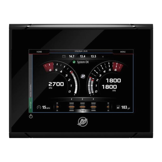
Section 1 - Getting Started A progress bar will be displayed, showing the operator that the process is taking place. After completing the calibration, the display will return to the Advanced Settings menu. 61499 Start‑up On start‑up with the power on and engines off, after the splash screen and advisory screen sequence, the main display will load and all data and graphics will be active. - Page 32 Section 1 - Getting Started 61487 After the systems check, if all engine parameters are within specifications, the VesselView will display the System OK message accompanied by a checkmark icon. 61488 90-8M0109374 JUNE 2016 Page 27...
-
Page 33: Engine Scheduled Maintenance
Engine Scheduled Maintenance If a maintenance reminder is detected during a system scan, the Mercury tab in the lower left‑hand corner of the screen will display in the color blue. Use common sense to protect your investment, and check your engine oil on a regular basis, preferably before each use. - Page 34 Section 1 - Getting Started Select the MAINTENANCE option. 61538 To view the remaining time before scheduled maintenance, select the MAINTENANCE LIFE option. The more of the progress bar shown in blue, the sooner scheduled maintenance is needed. 61539 90-8M0109374 JUNE 2016 Page 29...
-
Page 35: Device Maintenance
Section 1 - Getting Started 61540 Device Maintenance IMPORTANT: It is recommended that the supplied white plastic sun cover be installed for protection when the unit is not in service. Display Screen Cleaning Routine cleaning of the display screen is recommended to prevent a buildup of salt and other environmental debris. Crystalized salt can scratch the display coating when using a dry or damp cloth. -
Page 36: Section 2 - Initial Screens And Setup Wizard
Section 2 - Initial Screens and Setup Wizard Section 2 - Initial Screens and Setup Wizard Table of Contents VesselView Start‑up Advisory Screen........32 Tank Configuration ............40 Splash Screen..............32 Speed Setup ..............43 Setup Wizard................ 33 Finishing Setup Wizard ..........44 Import Configuration ............. -
Page 37: Vesselview Start-Up Advisory Screen
Splash Screen When the ignition key is turned on, a Mercury start‑up splash screen will appear. The Mercury logo will appear in the center of the screen. The logo will remain during the start‑up process. Do not try and rush the unit by pressing buttons during the start‑up stage. -
Page 38: Setup Wizard
Settings menu. Open the System Controls window. The System Controls window can be brought up by swiping from the top of the unit onto the screen. Select the Settings tile. 61504 Select the Mercury option on the left‑hand side of the screen. Select the System option. 61505 90-8M0109374... - Page 39 Section 2 - Initial Screens and Setup Wizard In the System menu, select the Setup wizard option. 61506 On the Device Configuration WELCOME screen select Next to begin the Setup wizard. 61507 Page 34 90-8M0109374 JUNE 2016...
-
Page 40: Import Configuration
Section 2 - Initial Screens and Setup Wizard Import Configuration To import an existing vessel configuration, insert a FAT or FAT 32 micro SD card with the configuration file and select this file in the drop‑down menu. If there is no import file, select Next to continue. 61508 Engine Setup In the Engine Setup screen, use the rotary knob or touch the menu fields to select the correct option. - Page 41 Section 2 - Initial Screens and Setup Wizard 61510 Selection 61515 Engine model Page 36 90-8M0109374 JUNE 2016...
- Page 42 Section 2 - Initial Screens and Setup Wizard 61512 Selection 61516 Joystick vessel 90-8M0109374 JUNE 2016 Page 37...
- Page 43 Section 2 - Initial Screens and Setup Wizard 61514 Selection 61517 Number of engines Page 38 90-8M0109374 JUNE 2016...
-
Page 44: Display Setup
Section 2 - Initial Screens and Setup Wizard 61513 Selection Display Setup Depending on the number of engines indicated in the Engine Setup screen, select the engines to be displayed by this VesselView unit. Up to four engines can be selected. Select Next to continue. 61522 90-8M0109374 JUNE 2016... -
Page 45: Device Setup
Section 2 - Initial Screens and Setup Wizard Device Setup In the Device Setup screen, use the rotary knob or touch the menu fields to select the proper options. If using multiple VesselView devices, be sure to assign unique numbers to each unit, to avoid data problems. Helm numbers should match the location of the individual VesselView unit. - Page 46 Section 2 - Initial Screens and Setup Wizard Select the tank row to be customized. 61524 61525 Select the tank type 90-8M0109374 JUNE 2016 Page 41...
- Page 47 Section 2 - Initial Screens and Setup Wizard Use the on‑screen keypad to enter the capacity. When finished entering tank capacity data, select OK to close the keypad. 61526 The tank position will populate the name field. To change the name of the tank, select the field and use the on‑screen keypad to customize the tank name.
-
Page 48: Speed Setup
Section 2 - Initial Screens and Setup Wizard Speed Setup In the Speed Setup menus, there are three options for determining how VesselView will acquire speed information. If the vessel is equipped with a GPS, the drop‑down menu will allow selection of available devices. If the vessel is equipped with a pitot sensor, this option will be selected. -
Page 49: Finishing Setup Wizard
Section 2 - Initial Screens and Setup Wizard Finishing Setup Wizard Select Finish to complete the Setup wizard on the VesselView. Do not power off the unit until the Finish screen is replaced by the vessel activity screen. 61530 Data Source Setup Data Sources To setup data sources, select the HOME tab at the top of the screen. - Page 50 Section 2 - Initial Screens and Setup Wizard VesselView will display numerous sources of data producing devices. For a general query of all detectable devices on the vessel, select the Auto Select option at the top of the list. Auto Select 61533 Auto select will search the network and compile a list of all devices that are detected during the auto select process.
-
Page 51: Enlarging Data Screens
Section 2 - Initial Screens and Setup Wizard Enlarging Data Screens To enlarge any of the data fields on the main VesselView screen, select the field. 61725 This will display the data at it's medium size on the screen. 61726 Page 46 90-8M0109374 JUNE 2016... -
Page 52: Instrument Bar
Section 2 - Initial Screens and Setup Wizard Selecting the data info field once more will display the selected data full screen. This can be helpful for viewing the screen from a greater distance, such as navigating from an auxiliary joystick position. Selecting the X will return the VesselView to the main navigation screen. - Page 53 Section 2 - Initial Screens and Setup Wizard The instrument bar is located on the right‑hand side of the display. The instrument bar contains text and numeric data in numerous tiles. Each tile in the instrument bar can be changed by the operator. There are also boating lifestyle options that will populate the data tiles with useful information for your type of boating.
- Page 54 Section 2 - Initial Screens and Setup Wizard In the menu screen, Bar 1 and Bar 2 options can be selected. These options will populate the instrument bar with engine and vessel data that is important to the style of boating that is selected. 61731 61732 90-8M0109374...
- Page 55 Section 2 - Initial Screens and Setup Wizard The result of selecting General in Bar 1 and Fishing in Bar 2, populates the instrument bar with both general vessel and engine data, as well as fishing pertinent data such as water temperature, live well temperature, and GPS coordinates. 61733 Selecting Edit...
- Page 56 Section 2 - Initial Screens and Setup Wizard A select and drop‑down menu screen will appear. Select the entry that corresponds to the type of data that you wish to populate the selected data tile in the Instrument bar. Actively selected data tile Entry and type of data to replace actively selected data tile...
- Page 57 Section 2 - Initial Screens and Setup Wizard 61737 Page 52 90-8M0109374 JUNE 2016...
-
Page 58: Section 3 - Autopilot Features And Operation
Section 3 - Autopilot Features and Operation Section 3 - Autopilot Features and Operation Table of Contents Economy Mode..............54 Cruise Control Mode............. 61 ECO................54 Cruise Control..............61 Smart Tow Mode..............57 Activating Cruise Control Mode ......62 Smart Tow..............57 Troll Control Mode.............. -
Page 59: Economy Mode
Section 3 - Autopilot Features and Operation Economy Mode ECO mode displays information to guide the operator in setting the optimum trim position and engine speed to achieve the best fuel economy. The engine control module (ECM) or propulsion control module (PCM) calculates the best fuel economy based on information from various sensors on the power package and vessel. - Page 60 Section 3 - Autopilot Features and Operation To actively monitor the ECO function of the VesselView, select the Vessel Control tab on the left‑hand side of the screen. This will open the autopilot functions bar. Select the ECO MODE option. 61750 61751 90-8M0109374...
- Page 61 Section 3 - Autopilot Features and Operation In the ECO Mode panel, VesselView shows the operator the RPM value and the trim position. If one or both of these operating parameters is out of optimization, the VesselView will display an orange arrow and/or orange sliders in the RPM and trim tiles. The direction of the orange arrows indicates where to adjust the RPMs and trim position to achieve fuel economy optimization.
-
Page 62: Smart Tow Mode
Section 3 - Autopilot Features and Operation To minimize the ECO Mode bar, select the arrow icon in the upper left‑hand corner of the bar. This will bring the Vessel Control bar to the main tiles. Select the X at the top left‑hand corner of the bar, or swipe the Vessel Control bar to the left to close it. 61754 61755 Smart Tow Mode... -
Page 63: Features
Section 3 - Autopilot Features and Operation The Smart Tow screen allows you to select, set, and modify settings in the Smart Tow features. The launch graph dot is animated when Smart Tow is active and performing a launch sequence. The dot will move along the launch path showing what part of the launch sequence the system is performing. - Page 64 Section 3 - Autopilot Features and Operation • Time is the length of time that the boat will remain above the selected speed. 61787 Five selection fields to create a profile To create a new profile, select Add profile. 61788 90-8M0109374 JUNE 2016 Page 59...
- Page 65 Section 3 - Autopilot Features and Operation Using the on‑screen keyboard, give the new launch profile a name. 61789 In the New Profile screen, the operator can edit each of the five selection fields. After all of the selections have been edited, select the Use button to utilize the new Smart Tow launch profile.
-
Page 66: Disabling Smart Tow
The cruise feature allows the operator to select a set point and adjust the value so the vessel maintains a specific speed or engine RPM. • Cruise is RPM based, unless the vessel incorporates a Mercury Marine GPS into the control area network. • If the vessel has a Mercury Marine GPS, the default setting is vessel speed. -
Page 67: Activating Cruise Control Mode
Section 3 - Autopilot Features and Operation Activating Cruise Control Mode To activate the Cruise autopilot option, select the Vessel Control tab on the left‑hand side of the screen. 61767 Select the Cruise Control tile in the Vessel Control bar. 61768 Page 62 90-8M0109374... - Page 68 Section 3 - Autopilot Features and Operation Select the up or down arrows to achieve the desired speed. 61769 With the desired cruise speed set, select the Enable tile in the cruise bar. Place the remote control handles in the forward gear position, and place the handles in the wide‑open throttle position.
-
Page 69: Troll Control Mode
Section 3 - Autopilot Features and Operation When Cruise is active the Vessel Control tab will be orange, alerting the operator that the vessel is in an autopilot control mode. 61771 Cruise Control mode can be cancelled by placing the remote control handles in the neutral position or by selecting the Disable tile in the bottom of the Cruise Control bar. - Page 70 Section 3 - Autopilot Features and Operation Select the Troll Control tile in the Vessel Control Bar. 61758 The vessel must be in gear and the throttle must be at idle. If the vessel does not meet these conditions, a warning icon and accompanying text will instruct the operator on how to make Troll Control available.
- Page 71 Section 3 - Autopilot Features and Operation When gear and throttle conditions are met, the Vessel Control bar will display Troll Control options. The increase and decrease arrows are grayed out when either the minimum or maximum RPM value has been selected. Select the + or – icons on the screen to adjust the RPM value.
- Page 72 Section 3 - Autopilot Features and Operation When the desired RPM value has been chosen, select the Enable tile. This will start Troll Control and the engines will climb to the desired RPM. 61762 The Enable tile will turn orange and read Disable. The Vessel Control tab will turn orange and display a warning symbol and the text Troll Active.
- Page 73 Section 3 - Autopilot Features and Operation The Vessel Control bar can be minimized during Troll Control operation without affecting the Troll Control autopilot function. Select the arrow in the upper left‑hand corner of the Vessel Control bar to minimize the bar. 61764 The main screen returns to normal size and the Troll Active tab is visible in orange on the left‑hand side of the screen.
- Page 74 Section 3 - Autopilot Features and Operation To disable troll control, select the Troll Active tab, which will display the Troll Control options bar. Select Disable to turn Troll Control off. 61766 90-8M0109374 JUNE 2016 Page 69...
- Page 75 Section 3 - Autopilot Features and Operation Notes: Page 70 90-8M0109374 JUNE 2016...
- Page 76 Section 4 - Setup and Calibrations Section 4 - Setup and Calibrations Table of Contents System Settings..............72 Sea Temp..............85 Navigation to the Settings Menu........72 Engines Settings..............85 Helm and Device Locations........... 72 Engines Shown.............. 85 Setup Wizard..............73 Engine Model..............
-
Page 77: System Settings
The Settings menu can be found by swiping downward from off the screen onto the upper portion of the screen. This will bring up the System Controls window. Select the Settings tile. A menu will appear on the left portion of the screen. Select Mercury from the list of options. -
Page 78: Setup Wizard
The Settings menu can be found by swiping downward from off the screen onto the upper portion of the screen. This will bring up the System Controls window. Select the Settings tile. A menu will appear on the left portion of the screen. Select Mercury from the list of options. - Page 79 Section 4 - Setup and Calibrations Select the Vessel settings option. 61659 Select the Tabs option. 61660 Tabs settings allows the operator to display the tab positions on the screen by selecting the Show checkbox. The Source option allows selecting the outboard or drive that carries the Tab sensor data to the network. The tab sensor data is sent by one of the outboards or drives on the vessel.
- Page 80 Section 4 - Setup and Calibrations In addition to the PCM selections, there are options to select either the TAB—trim tab interface module, or the TVM—thrust vector module, to send tab data to the VesselView. 60056 Drive assignment options PCM0 = starboard or starboard outer PCM1 = port or port outer PCM2 = starboard inner or center PCM3 = port inner...
-
Page 81: Tanks
Section 4 - Setup and Calibrations The Set outboard or drive to Zero is the actual tab position that will read 0% on the display. Operators can determine at which point the vessel runs flat in the water. At this running position, the tabs may actually be at a percentage of downward angle. The Set to Zero option allows the operator to have the optimal flat aspect of the vessel read as 0% on the gauge. -
Page 82: Speed
Section 4 - Setup and Calibrations When tank calibration is complete, select Save and the unit will return to the navigation screen. Speed Speed settings allow the operator to select the type of sensor or sender that the VesselView will receive speed data from. Speed settings can be configured using this menu. - Page 83 PCM3 = port inner Pitot type options include 100 psi and 200 psi. The 200 psi option only applies to select Mercury Racing outboard models. The pitot multiplier will use 1.00 as a default setting and can be increased or decreased to correct speed display readings that read too high or too low.
- Page 84 Section 4 - Setup and Calibrations Select the outboard or drive that will send paddle wheel data to the VesselView. Use the following images to determine the proper selection. 61687 60056 Drive assignment options PCM0 = starboard or starboard outer PCM1 = port or port outer PCM2 = starboard inner or center PCM3 = port inner...
- Page 85 Paddle wheel frequency can be changed to match the requirements of different sensors. The frequency of the paddle wheel speed sensor offered by Mercury Marine is 4.9 Hz per mile or 5.7 Hz per knot. Check the instructions that came with the paddle wheel for specific information on the paddle wheel frequency output.
-
Page 86: Steering
Section 4 - Setup and Calibrations Steering Steering source data can be selected to come from either the PCM or the TVM—thrust vector module, with options to display the data on‑screen, to invert steering input, and to establish a steering offset degree. 61697 60056 Drive assignment options... -
Page 87: Vessel Control
Section 4 - Setup and Calibrations Steering Offset is used to align the outboard, sterndrive, or inboard to zero degrees. When the drive is positioned perpendicular to the hull, the steering angle displayed on‑screen may not match the steering sensor on the drive. To adjust for this variance, select the Offset window. -
Page 88: Cameras Installed
Section 4 - Setup and Calibrations Selections for autopilot features are Cruise, Troll, Smart Tow, and Eco Mode. A Reset to defaults will uncheck any or all of the autopilot features that are not available based on the power package of the vessel chosen in the Setup Wizard. 61709 NOTE: If after the Reset to defaults option is chosen, all of the boxes are unchecked, your engine does not support the autopilot features of the VesselView. -
Page 89: Genset Enabled
Section 4 - Setup and Calibrations Genset Enabled Genset enabled allows the VesselView to query the network for genset data. 61702 Maintenance Notification The Maintenance notification checkbox will allow VesselView to display scheduled maintenance pop‑ups on‑screen. 61703 Page 84 90-8M0109374 JUNE 2016... -
Page 90: Sea Temp
The Settings menu can be found by swiping downward from off the screen onto the upper portion of the screen. This will bring up the System Controls window. Select the Settings tile. A menu will appear on the left portion of the screen. Select Mercury from the list of options. -
Page 91: Engine Model
Section 4 - Setup and Calibrations Engines shown is covered during the Setup Wizard process, but display options can be changed in the Engines settings menu at any time. VesselView can display up to four engines, depending on the number of engines chosen during the Setup Wizard process. -
Page 92: Limits
Setting menu. Increasing or decreasing the warning minimums and maximums is generally regarded as the boater's personal preference. NOTE: If the operator is utilizing the Navico side of the MFD, and any min/max warning limits in the Mercury side are exceeded, there will be an alert beep generated. -
Page 93: Supported Data
Section 4 - Setup and Calibrations Supported Data Supported Data allows the operator to select the types of data that the VesselView will display. The list of data sources is dependent on the power package selected during the Setup Wizard. Select the checkbox for each data item you want VesselView to be able to display. -
Page 94: Eco Mode
Section 4 - Setup and Calibrations ECO Mode The ECO Mode menu option shows the current operating parameters to keep the engine optimized for the best fuel efficiency. The operator can check these ECO parameters without being in the ECO Mode. Selecting Refresh will evaluate engine data and adjust the RPM recommendations as needed. -
Page 95: Cruise/Smart Tow Type
Section 4 - Setup and Calibrations Cruise/Smart Tow Type The Cruise/Smart Tow type setting allows the operator to select the sensor from which the Cruise autopilot program and the Smart Tow program launch profiles get their speed data. Engine RPM or GPS speed data are the options. Selecting Auto will make VesselView query the network for a source of speed based data and use that selection for the Cruise and Smart Tow features. -
Page 96: Alarms
Section 4 - Setup and Calibrations To calibrate the trim, trim the engines all the way in and record the reading—row 1, this will be the trim actual 0%. Trim the engines all the way out, record the reading—row 3, this will be the trim actual 100%. The Zero point is when the engines are positioned parallel with the bottom of the vessel, record that position. -
Page 97: Export
Section 4 - Setup and Calibrations Personality File Export A vessel Personality file is made up of all of the settings that have been made within a VesselView device. To export this personality, insert a SD card into the card port slot and select Export. Remove the SD card and transfer that file to another VesselView device using the Import option. -
Page 98: Import
Section 4 - Setup and Calibrations 61721 Select Yes The new Personality file will be written to the top level of the memory card. It will not be placed inside any folders on the SD card. Import To Import a Personality file, insert an SD card into the card port that has a VesselView written Personality file stored on it. Select Import. - Page 99 Section 4 - Setup and Calibrations You will be prompted one more time to replace all existing settings. Select Yes. The VesselView will import the new Personality file and the unit will restart. 61723 Page 94 90-8M0109374 JUNE 2016...
- Page 100 Section 5 - Warning Alarms Section 5 - Warning Alarms Table of Contents Warnings—Faults and Alarms..........96 Shallow Water and Low Fuel Alarms ....98 90-8M0109374 JUNE 2016 Page 95...
-
Page 101: Warnings-Faults And Alarms
Warnings—Faults and Alarms All Mercury warnings, faults and alarms will be shown regardless of what screen is displayed at the time of the alarm. When an alarm is activated, the screen will display a window showing the alarm text and warning, along with a brief description of what action should be taken. - Page 102 Section 5 - Warning Alarms Noncritical alarms will display like critical alarms, but are accompanied by six short beeps from the warning horn. 61545 Fault pop‑ups allow the operator to get additional information regarding the individual faults. Select the Details option to view a more descriptive explanation of the fault.
-
Page 103: Shallow Water And Low Fuel Alarms
To clear an active fault have the faulty or failed part inspected, repaired or replaced and start‑up the engines and VesselView and allow the unit to go through the system start‑up scan. If the vessel passes the start‑up scan the Mercury tab on the left‑hand side of the screen will display in green. - Page 104 Section 5 - Warning Alarms These types of faults will not turn the Mercury tab to red. Instead, the upper header bar will turn red and display the international warning symbol. 61778 To view the fault select the main menu screen, then choose the Alarms option. Here, the fault can be viewed, and the settings that raised the fault can be changed.
- Page 105 Section 5 - Warning Alarms 61779 61780 Page 100 90-8M0109374 JUNE 2016...
Need help?
Do you have a question about the VesselView Link and is the answer not in the manual?
Questions and answers
add item to systems display
To add Mercury VesselView Link to the system's display:
1. Power on all devices and key on all engines.
2. Swipe down from the top of the screen to open the System Controls window.
3. Select the "Settings" tile.
4. On the left side, select the "Network" option.
5. Select "Sources...".
6. Use the "Auto Select" option to detect and list all connected devices.
7. Confirm that VesselView Link is listed among the detected sources.
This process allows the system to detect and integrate data from the VesselView Link into the display.
This answer is automatically generated