Interroll MultiControl Instruction Manual
Hide thumbs
Also See for MultiControl:
- User manual (64 pages) ,
- Operating and programming manual (131 pages)
Table of Contents
Advertisement
Quick Links
Advertisement
Table of Contents
Troubleshooting

Related Manuals for Interroll MultiControl


Summary of Contents for Interroll MultiControl
- Page 1 Instruction Manual Interroll MultiControl 1103563...
- Page 2 All trademarks contained in this document (protected trademarks, such as logos and business names) are the property of Interroll Engineering GmbH or third parties and may not be used, copied or distributed without prior written consent..
-
Page 3: Table Of Contents
Table of contents About this document............................1 Information about this user manual ......................1 Warning notices in this manual ........................2 Symbols ................................. 3 Safety related information..........................4 State of the art ..............................4 Intended use ................................ 4 Areas of application ............................4 Unintended use .............................. - Page 4 Transport ................................15 Storage ................................15 Assembly and installation ..........................16 Warning instructions for assembly ......................16 Assembling the MultiControl ........................16 Initial assembly ..............................16 Repeated assembly ............................18 Warning instructions for electrical installation ..................19 Electrical installation ............................20 Connecting the power supply ........................
- Page 5 Stop ..................................44 Procedure in case of accident or malfunction ..................45 Maintenance and cleaning ........................... 46 Maintenance ..............................46 Check the MultiControl ..........................46 Replace the MultiControl..........................46 Cleaning ................................47 Troubleshooting ............................... 48 Meaning of the LED ............................48 General LED..............................
- Page 6 Decommissioning and disposal ........................56 Decommissioning ............................. 56 Disposal ................................56 Appendix ................................57 10.1 Accessories ................................ 57 10.2 Declaration of conformity ..........................58 Version 3.0 (08/2018) Translation of original instruction manual...
-
Page 7: About This Document
In the further course, the term "control" is used alternatively. The instruction manual is part of the product and contains important notes and information on the various operating phases of the MultiControl. It describes the MultiControl at the time of its delivery by Interroll. -
Page 8: Warning Notices In This Manual
About this document 1.2 Warning notices in this manual Warning notices are given in the context in which a hazard can occur to which the warning notices refer. They are structured according to the following pattern: SIGNAL WORD Type an source of danger ➢... -
Page 9: Symbols
About this document 1.3 Symbols This symbol indicates useful and important information. ✓ This symbol indicates a prerequisite that must be met before installation or maintenance work. This symbol represents general safety-related information. This symbol marks the steps to be carried out. ➢... -
Page 10: Safety Related Information
The MultiControl may only be used in industrial environments for industrial purposes within the specified performance limits specified in the technical data. It controls up to four Interroll RollerDrive or VDC Motors and must be integrated into a conveyor unit or conveyor system before commissioning. -
Page 11: Unintended Use
The use of the MultiControl is not intended for private end users! Use in a residential environment is prohibited without further testing and without the use of appropriately adapted EMC protective measures! 2.4 Personnel qualification... -
Page 12: Dangers
➢ restart. Immediately contact qualified personnel to determine the cause of the fault. ➢ Maintenance Since it is a maintenance-free product, it is sufficient to check the MultiControl regularly for ➢ visible damage. Never open the MultiControl! ➢ Unintentional start up Ensure that the connected RollerDrive / motors cannot start unintentionally, especially ➢... -
Page 13: Interfaces To Other Devices
Safety related information 2.6 Interfaces to other devices When integrating the MultiControl into a conveyor system, danger spots may arise. These danger spots are not part of these operating instructions and must be analysed during the development, installation and commissioning of the conveyor system. -
Page 14: Additional Documentation
Safety related information 2.8 Additional documentation The MultiControl is part of the Interroll DC platform, consisting of: • Power control • RollerDrive • RollerDrive-Control Follow the instructions in the manuals of the connected devices. The supplementary document "Interroll MultiControl - Operating and Programming" contains further notes on the operating and programming of the MultiControl. -
Page 15: Product Information
Product information 3.1 Product description The MultiControl is a conveyor control system that can control up to four Interroll RollerDrive. It is also a certified I/O device for PROFINET, EtherNet/IP and EtherCAT and can thus be networked with other MultiControls and a PLC. -
Page 16: Structure
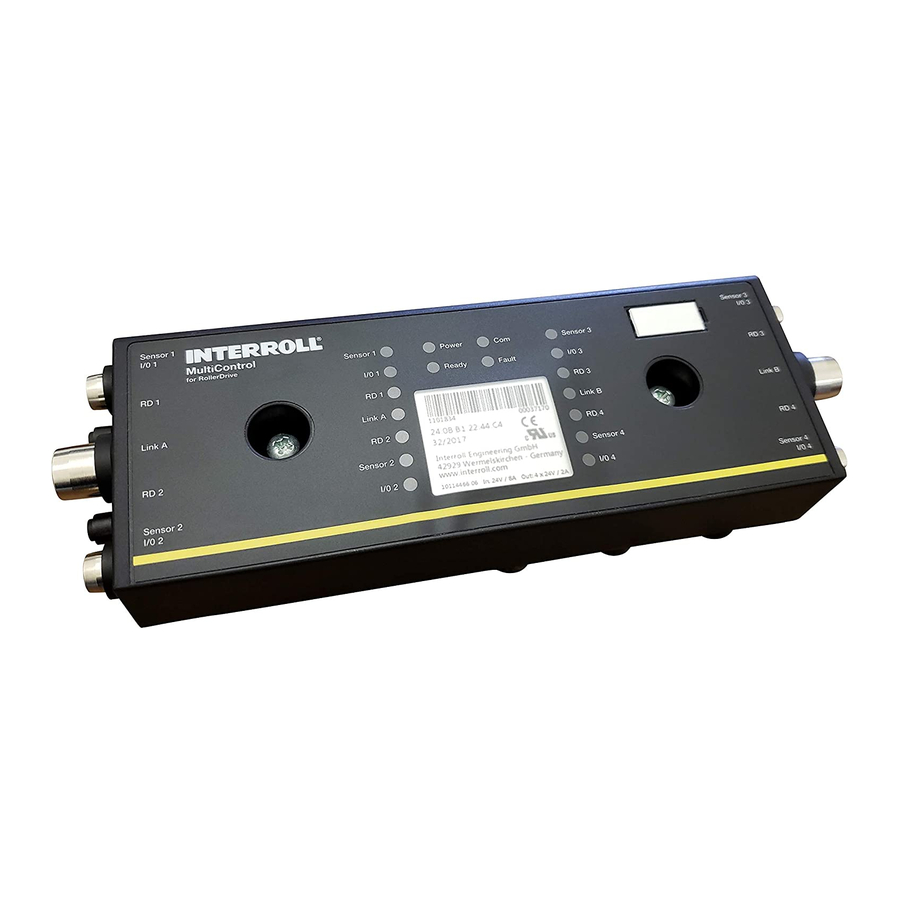
Product information 3.2 Structure MultiControl 1 Magnetic sensor 9 Connection motor RD 4 2 LEDs for left-hand connections 10 Connection sensor 4 / I/O 4 3 General LEDs 11 Fastening screw 4 LEDs for right-hand connections 12 Nameplate 5 Labelling field... -
Page 17: Baseplate
2 RollerDrive power supply flat cable guide (L2) 3 Screw guides for fastening the MultiControl 4 Holes for fastening the MultiControl to the baseplate 3.3 Scope of delivery The scope of delivery of the MultiControl includes the following parts: • MultiControl •... -
Page 18: Nameplate
Product information 3.4 Nameplate The information on the nameplate enables the identification of the MultiControl. This is necessary in order to use the MultiControl as intended. 1 Article number 5 Serial number 2 MAC address 6 UL mark 3 Week and year of production... -
Page 19: Technical Data
Voltage range L2 22 to 28 V DC Current consumption Logic supply voltage: MultiControl: max. 0,2 A + connected sensors/actors = max. 1,6 A Motor supply voltage: RollerDrive rated current: 4 x 1,75 A = 7 A RollerDrive start up current: 4 x 3,5 A = 14 A... -
Page 20: Dimensions
Product information 3.6 Dimensions The distance from the MultiControl to neighbouring components must be at least 10 mm in order to operate the magnetic sensor. Version 3.0 (08/2018) Translation of original instruction manual... -
Page 21: Transport And Storage
In the event of damage in transit, inform the transport company or Interroll immediately in ➢ order not to lose any claims for damages. Do not expose the MultiControl to extreme temperature changes, as this can lead to the ➢ formation of condensation. -
Page 22: Assembly And Installation
To attach the MultiControl to the conveyor frame, first attach the enclosed base plate to the conveyor frame. There are two holes in the base plate for mounting the MultiControl. For the first installation, the left holes should be used. - Page 23 Place the MultiControl on the left-hand bore and press until the lock engages. ➢ Screw the MultiControl to the base plate (tightening torque: max 2Nm). As a result, the ➢ piercing contacts are driven through the flat cable and made the contact with the power supplies.
-
Page 24: Repeated Assembly
Assembly and installation Repeated assembly If an already connected MultiControl has to be detached from the base plate, the flat cables must not be contacted again at the same point, as otherwise proper contact cannot be ensured. So that the flat cables do not have to be loosened and moved on all MultiControl, the MultiControl can in this case be fastened via the respective right-hand mounting hole. -
Page 25: Warning Instructions For Electrical Installation
MultiControl or the bus line. ➢ Make sure all components are properly grounded. Improper grounding can lead to static charge, which may result in failure or premature failure of the MultiControl. ➢ Provide suitable switching and protective devices that enable safe operation. -
Page 26: Electrical Installation
By using two flat cables, the RollerDrive and the sensors / logic are powered separately. This enables safe switching off of the RollerDrive without losing the bus communication. To use the MultiControl as a spare part in existing systems, a FK distributor can be used (see "Accessories"). -
Page 27: Connecting The Rollerdrive
Assembly and installation Seal the ends of the flat cables with end caps to achieve IP54 protection. ➢ Mount the MultiControl on the base frame to establish the correct contact bonding (see ➢ „Initial assembly“, page 16). Connect cables to the voltage source. Connect the brown wire to L + and the blue wire to ➢... -
Page 28: Connecting The Bus
If a connection remains unused, seal it with an M12 dummy cap to achieve IP54 protection. ➢ On both sides of the MultiControl it is possible to connect the shielding of the bus cables. This minimizes EMC problems. Version 3.0 (08/2018) -
Page 29: Connecting The Sensors
Connections are not short-circuit proof In the event of a short circuit, in particular between pin 1 and pin 3, the internal fuse (PTC) in the MultiControl triggers. Normal operation is possible again after the internal fuse has cooled down. -
Page 30: Overview Connections
Assembly and installation Characteristic values for the outputs Output Type DC General Use Maximum output current ≤ 200 mA Output voltage „1“ with PNP > 15 V @ 200 mA Output voltage „1“ with NPN ≤ 5 V @ 200 mA If a sensor connection remains unused, seal it with an M8 dummy cap to achieve IP54 ➢... -
Page 31: Initial Start Up And Operation
Make sure that the base plate of the MultiControl has been properly fastened to the ➢ profile, that the MultiControl has been correctly fixed to the base plate and that all screws have been tightened properly. Ensure that the interfaces to other components do not create any additional danger areas. -
Page 32: User Interface
Initial start up and operation 6.3 User interface The MultiControl has an integrated web server that generates a user interface for configuring the MultiControl. This user interface can be called up via a computer connected to the MultiControl. Except for a web browser, no additional software needs to be installed on the computer. -
Page 33: Homepage "Multicontrol Overview
• Information about the selected application program All illustrated pages in this chapter reflect the respective factory settings. To exit the user interface click on "Log Out" (not necessary, if the MultiControl is restarted). ➢ Version 3.0 (08/2018) Translation of original instruction manual... -
Page 34: Network Settings
Initial start up and operation Network Settings In order for the MultiControl to be integrated into an automation system, bus parameters may need to be changed. These include the setting of the bus type used and an addressing. The MultiControl supports the following bus types: •... - Page 35 Initial start up and operation • IP addresses of neighbour MultiControls (for ZPA and ZPA + programs) IP address upstream: Address of the MultiControl to be taken over by the conveyed items IP address downstream: address of the MultiControl to the conveyed items •...
-
Page 36: Motor Settings
"Acceleration" and "Deceleration" change the start / stop behaviour of the RollerDrive. The parameter "Alternate speed" currently has no function. To apply the changed parameters to the MultiControl, press the "Submit" button. Version 3.0 (08/2018) Translation of original instruction manual... -
Page 37: Digital I/O - States
Initial start up and operation Digital I/O - States Display of the switching states of the connected sensors and I/O. No real-time status! Status changes are only visible after updating the web browser (key "F5"). Version 3.0 (08/2018) Translation of original instruction manual... -
Page 38: Digital I/O - Settings
Initial start up and operation Digital I/O - Settings The sensors 1 - 4 are basically assigned to the zone sensors. By using an optional Y-cable additional I/O can be connected. I/O 1 to I/O 4 can be configured as inputs or outputs with the following functions: Function Comment None... - Page 39 Depending on the selected control program, the functions vary (see the description of the control programs in the supplementary document "Interroll MultiControl - Operating and Programming"). To apply the changed parameters to the MultiControl, press the "Submit" button. Version 3.0 (08/2018) Translation of original instruction manual...
-
Page 40: Control Program
Depending on the selected control program, the functions and factory settings of the timers vary (see description of the control programs in the supplementary document "Interroll MultiControl - Operating and Programming"). To apply the changed parameters to the MultiControl, press the "Submit" button. Version 3.0 (08/2018) Translation of original instruction manual... -
Page 41: Error - State
Initial start up and operation Error - State • Display of the current status of the MultiControl • Display of the current error • Display of the last error that occurred Version 3.0 (08/2018) Translation of original instruction manual... -
Page 42: Error - Settings
Immediate Stop: Error is indicated by the fault LED flashing twice. The conveying process is interrupted. If the MultiControl is operated without PLC, we recommend the setting "Ignore". If the MultiControl is operated with PLC, we recommend the setting "Immediate Stop". - Page 43 "Immediate Stop" and "Normal Stop" have the same behaviour. The settings of Control Error 1 - 8 have no function. To apply the changed parameters to the MultiControl, press the "Submit" button. Changes only become effective after switching the controller off / on.
-
Page 44: Error - Log
Initial start up and operation Error - Log Error log of the last occurred errors / messages with time stamp. For explanation of error codes, see "Error Codes", page 53. Version 3.0 (08/2018) Translation of original instruction manual... -
Page 45: Service - Teach-In
Initial start up and operation Service - Teach-in Service - Plug&Play The functions "Teach-In" and "Plug & Play" are described in the supplementary document "Interroll MultiControl - Operating and Programming". Version 3.0 (08/2018) Translation of original instruction manual... -
Page 46: Service - Change Password
➢ Button „Submit“ ➢ NOTICE Destruction of the MultiControl due to premature shutdown of the supply voltage ➢ Ensure that the power supply is uninterrupted until the restart is complete. Duration of the process about two minutes. Version 3.0 (08/2018) -
Page 47: Service - Restart
➢ Button „Submit“ ➢ During the restart of the MultiControl, an existing bus connection to a computer or a PLC is interrupted and must then be rebuilt. Service - Version Display of the serial number and the software version of the MultiControl. -
Page 48: Service - Up-/Download
Initial start up and operation Service - Up-/Download The settings of the MultiControl can be downloaded via the user interface and saved on a computer. When replacing the MultiControl, the settings can be restored with the data backup. Save the desired file by right-clicking and "Save as" on the connected PC. -
Page 49: Magnetic Sensor
To operate the magnetic sensor, a magnet is required (see "Accessories", page 57). The magnetic sensor is located at the top of the MultiControl, between the two "R" of the word "INTERROLL" just before the base plate (see "Structure", page 10). -
Page 50: Operation
➢ Before switching on the power supply, make sure that there are no persons in the danger areas of the conveyor system. If the MultiControl acts as an I / O device, it cannot automatically start or stop motors or perform other actions. It requires commands from a higher-level controller, e.g. -
Page 51: Procedure In Case Of Accident Or Malfunction
Initial start up and operation 6.7 Procedure in case of accident or malfunction Immediately stop the conveyor system, de-energize it and secure against unintentional ➢ restart. In case of an accident: provide first aid and make an emergency call. ➢ Inform responsible supervisor. -
Page 52: Maintenance And Cleaning
In the course of regular inspection and maintenance work on the conveyor, make sure that ➢ the screws of the MultiControl are still tightened and the cables are still correctly routed and connected to the corresponding connections. Replace the MultiControl If a MultiControl is damaged or defective, it must be replaced. -
Page 53: Cleaning
Damage to the MultiControl due to improper cleaning ➢ Do not immerse the MultiControl in liquids. If necessary, vacuum dust and dirt. ➢ For more thorough cleaning, disconnect the MultiControl from the power supply, remove it ➢ and clean it with a damp cloth. Version 3.0 (08/2018) -
Page 54: Troubleshooting
Troubleshooting Troubleshooting 8.1 Meaning of the LED LED on the MultiControl inform about the operating status of the conveyor. Status description of the LED: • Off: LED is permanently off • On: LED is permanently on • Flashing 1 Hz: LED flashes at a frequency of 1 Hz; Duty cycle 1:1 •... - Page 55 Troubleshooting Power Ready Fault Meaning Priority Flashes Voltage error overvoltage Flashes Temperature in the MultiControl too high. Flashes Overload protection of the brake chopper resistor active. Flashes Handshake communication disturbed. See the instructions for ZPA and ZPA + applications. Flashes No connection to the neighbour.
-
Page 56: Led Of The Connections
8.2 Troubleshooting The MultiControl is a complex system. There are many correlations between all participants in the system. In such a system, of course, errors can also arise, which can result either from the conveying processes or from the interaction of the individual components. Not all errors can be displayed in detail and a correlation between the location and the location of the display is not always possible. - Page 57 ➢ Overvoltage Power supply is over 30 V supply is below 30 volts Make sure that the ➢ The MultiControl does No or insufficient power power supply is within not work or does not supply the specified voltage work properly...
- Page 58 Troubleshooting Error Possible cause Remedy Make sure that the ➢ RollerDrive does not RollerDrive not inserted or not power supply is within rotate correctly inserted or the specified voltage RollerDrive defective range Check connections and ➢ correct if necessary If necessary, replace ➢...
-
Page 59: Error Codes
Troubleshooting Error codes Short text Comment ApplErrorNone No error in the application program ApplErrUnk Unknown error in the application program ApplErrSystemSevere Severe system error ApplErrSystemMinor Minor system error ApplErrSystemWarning Warning PllErrItemNotFound Searched object was not found ApplErrRange Number outside the valid value range ApplErrNoTerminlInput Terminal has no input data ApplErrStopByOperator... - Page 60 Troubleshooting Short text Comment ApplErrErrorLogUpdate Access error on the error log file ApplErrPanellllMode Change of mode not allowed ApplErrPanelLedBlocked Access to LED control not allowed ApplErrInvalidApplConf Invalid configuration of the application program ApplErrDriveError1 Error RollerDrive 1 ApplErrDriveError2 Error RollerDrive 2 ApplErrDriveError3 Error RollerDrive 3 ApplErrDriveError4...
- Page 61 Troubleshooting Short text Comment ApplErrMotorVoltage Voltage error: Motor voltage is missing ApplErrOvcOverloaded Overload of the brake chopper resistor ApplErrRemoteEmergency Emergency stop from the transfer neighbour ApplErrInvalidStateTblConf Error while loading the application program ApplErrNewStateTable New application program loaded ApplErrInvalidErrConf Invalid configuration for the selected application program ApplErrInvalidTeachParams Invalid parameters for teach-in procedure...
-
Page 62: Decommissioning And Disposal
9.1 Decommissioning Remove all cables from the MultiControl. ➢ Loosen the screws with which the MultiControl is fastened to the base plate and remove ➢ the MultiControl. If the MultiControl is to be completely disassembled, also loosen the screws that fix the ➢... -
Page 63: Appendix
Flat cable for power supply (25 m) S-1004030 Power supply PowerControl S-1004029 Magnetic key S-64100210 MultiControl Y line S-1104460 MultiControl communication cable (3 m) S-1104438 MultiControl dummy plug S-1104466 Package: 3 x RollerDrive M8 pluggable 3 x Sensor M8 screwable 1 x Communication M12 screwable... -
Page 64: Declaration Of Conformity
Hereby the manufacturer Interroll Engineering GmbH Hoeferhof 16 D-42929 Wermelskirchen Deutschland • Interroll MultiControl - Model number 1103563 declares compliance with the relevant provisions and the associated CE marking to the above guideline. Reference of harmonized standards: EN 61326-1:2013 EN 61000-3-2:2014... - Page 66 © Copyright For your local contact visit Interroll.com/contact/...
Need help?
Do you have a question about the MultiControl and is the answer not in the manual?
Questions and answers