Interroll MultiControl User Manual
Hide thumbs
Also See for MultiControl:
- Operating and programming manual (131 pages) ,
- Instruction manual (66 pages)

Related Manuals for Interroll MultiControl


Summary of Contents for Interroll MultiControl
- Page 1 INSPIRED BY EFFICIENCY User Manual Interroll MultiControl Version 2.3 (01/2017) en-US Translation of original instruction manual...
- Page 2 All signs contained in this document (registered trademarks, such as logos and business designations) are the property of Interroll Engineering GmbH or third parties and may not be used, copied or distributed without prior written consent.
-
Page 3: Table Of Contents
Ambient conditions for transport and storage.................. 15 Transport................................ 15 Storage ................................ 15 Assembly and installation ..................... 16 Warning information for assembly...................... 16 Assembly of MultiControl.......................... 16 Initial assembly............................ 16 Repeated assembly .......................... 17 Warning notices concerning the electrical installation .............. 18 Version 2.3 (01/2017) en-US... - Page 4 Configuration options .......................... 23 User interface............................ 24 Service Data Objects (SDO)....................... 25 Magnetic sensor............................. 25 Configuring MultiControl .......................... 28 Setting bus parameters ........................ 28 Selecting the application module ...................... 29 Configuring inputs and outputs...................... 29 Defining the motor type........................ 29 Switching off the LED indicators ......................
- Page 5 Interroll MultiControl Table of Contents Cyclical process image.......................... 44 Input................................ 44 Output .............................. 48 Acyclical data ............................... 50 Version information .......................... 50 Manufacturer information ........................ 50 Diagnostic information ......................... 50 Error information ........................... 51 Network online time.......................... 51 Control program information...................... 51 Bus parameters............................
-
Page 6: Introduction
Contact persons close to you can be found on the Internet under www.interroll.com/contacts. Warning notices in this manual The warning notices refer to risks which may arise while usage the MultiControl. They are available in four danger levels identified by the signal word: Signal word... -
Page 7: Safety
Safety State of the art The MultiControl has been built to comply with the state of the art and is operationally safe in its delivered state. Nevertheless, users may encounter hazards during use: Disregarding the notices in this manual may lead to serious injury. -
Page 8: Dangers
4 Work on the device must be performed only by authorized qualified persons in accordance Bodily injury with the applicable regulations. 4 Before using the MultiControl, ensure that no unauthorized personnel is in the vicinity of the conveyor. Electricity 4 Only perform installation and maintenance work in the de-energized state. -
Page 9: Interfaces To Other Devices
4 After assembling the MultiControl in a conveyor module, check the whole system for a new potential dangerous spot before switching on the conveyor. -
Page 10: Product Information
MultiControl. If a special conveyor logic is to be used, the MultiControl can be equipped with a special software by Interroll. As a result, it can be used as an individual control system – with or without connected PLC. -
Page 11: Structure
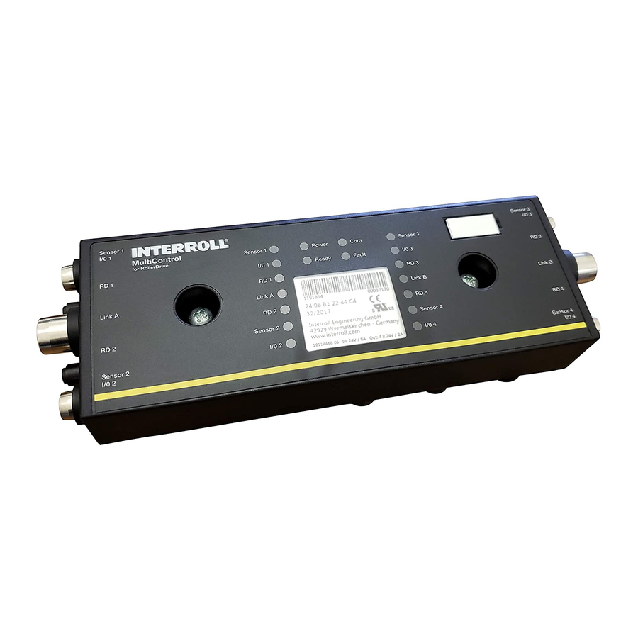
Interroll MultiControl Product information The MultiControl does not provide a protective mechanism against excessive temperature of the connected drive motor. Structure Sensor 1 ® Sensor 3 I/0 1 I/0 3 MultiControl Sensor 1 Power Sensor 3 for RollerDrive I/0 1... -
Page 12: Scope Of Supply
Interroll MultiControl Product information Scope of supply The scope of supply of the MultiControl contains the following components: • MultiControl • Baseplate • Two screws for fastening the MultiControl to the baseplate Nameplate The information on the nameplate is used to identify the MultiControl. -
Page 13: Technical Data
Sensor 4 I/0 2 I/0 4 MultiControl The distance from the top edge of the MultiControl to neighboring components must be at least 10 mm to be able to operate the magnetic sensor. Version 2.3 (01/2017) en-US Translation of original instruction manual... - Page 14 Interroll MultiControl Product information 32.5 32.5 Mounting plate Version 2.3 (01/2017) en-US Translation of original instruction manual...
-
Page 15: Transport And Storage
4 In the event of damage, take photos of the damaged parts. 4 Report any damage caused by transport immediately to the transport company and Interroll to retain the right to claim for compensation. 4 Do not expose the MultiControl to serious temperature fluctuations as this could result in condensation. Storage... -
Page 16: Assembly And Installation
In the case of curves, wherever possible the MultiControl should be assembled on the outside radius as the RollerDrive connection is on this side. The distance from the top edge of the MultiControl to neighboring components must be at least 10 mm to be able to operate the magnetic sensor. -
Page 17: Repeated Assembly
Interroll MultiControl Assembly and installation 4 Place the MultiControl onto the left hole in each case and push it down until the locking mechanism engages. 4 Fasten the MultiControl with the available screws in MultiControl and a Phillips screwdriver onto the baseplate according to DIN EN ISO 4857-Z2. Maximum tightening torque 2 Nm. -
Page 18: Warning Notices Concerning The Electrical Installation
4 Before the installation, wiring or removal of the MultiControl, de-energize it and secure it against inadvertent reactivation. 4 The MultiControl may be operated only with DC voltage with a rated voltage of 24 V and a maximum permissible deviation of ±5 %. -
Page 19: Electrical Installation
The two ground potentials (L-) of the voltage supply are connected with each other in the MultiControl. The two positive contacts (L+) are connected with each other via a diode in the MultiControl. This ensures that the logic can also be supplied via the RollerDrive line, but not the RollerDrive via the logic supply. -
Page 20: Connecting The Rollerdrive
4 Connect the line to the voltage source by connecting the brown core at L+ and the blue core at L-. If the MultiControl has to be removed after bonding, the flat cable must not be reconnected at the same point as otherwise a proper contact cannot be ensured. In this case, the MultiControl has to be repositioned (see "Repeated assembly", page 17). -
Page 21: Connecting The Bus
Receive Data RD+ Receive Data RD- The MultiControl is equipped with an integrated 2-port switch. This allows the MultiControl, e.g. to be integrated in line structures of the bus wiring. 4 Observe the installation guidelines of the respective bus systems: •... -
Page 22: Connecting The Sensors
The connectors 'Sensor 1, I/O 1' to 'Sensor 4, I/O 4' can be used to connect four sensors and four additional inputs and outputs (Aux I/O) to the MultiControl. PNP or NPN sensors as well as sensors with opening or closing contacts can be used. The sensor type and the function of the additional I/Os can be parameterized (see "Configuring inputs and outputs", page 29). -
Page 23: Initial Startup And Operation
4 Ensure there are no bystanders in dangerous areas around the conveyor. Configuration options To start up the MultiControl, it has to be configured first. There are several ways to achieve this: • All settings can be configured using a web-based user interface on a computer connected to the MultiControl (see "User interface", page 24). -
Page 24: User Interface
The MultiControl features an integrated web server generating a user interface for configuring the MultiControl. This user interface can be called up in a web browser on a computer connected to the MultiControl. Except for a web browser, no other software has to be installed on the computer. -
Page 25: Service Data Objects (Sdo)
4 Hold the magnet at the magnetic sensor. When the magnetic sensor recognizes the magnet, the "Fault" LED is permanently lit. After 1 second, running lights start on the LED bar on the left side of MultiControl. Every LED is assigned a function (see table below). - Page 26 4 To change this second selection, hold the magnet against the magnetic sensor again after 2 seconds. Running lights are lighting up on the LED bar on the right side of MultiControl, which can be used to perform additional settings in the same way. The selection is accepted 5 seconds after removing the magnet.
- Page 27 Function 5: Switch LED indicators on or off I/O 2 Function 6: Reset MultiControl to factory settings I/O 2 + Confirmation for function 6: Reset MultiControl to factory settings I/O 4 Sensor 3 Flashes 1 Hz Loading EtherCAT stack I/O 3...
-
Page 28: Configuring Multicontrol
Initial startup and operation Configuring MultiControl Setting bus parameters Bus parameters may have to be changed for MultiControl to be integrated into an automation system. This includes the setting of the bus type used and an addressing. MultiControl supports the following bus types: •... -
Page 29: Defining The Motor Type
Interroll MultiControl Initial startup and operation Selecting the application "I/O Device" must be selected here to operate the MultiControl as I/O device. The adjustable module timers 1 to 4 are without effect here and should not be adjusted. When using the MultiControl with other internal programs, the corresponding program must be selected here , and the timers 1 to 4 be adjusted to the conveyor system. -
Page 30: Resetting To Factory Settings
• Magnetic sensor: Function 6 (LED "I/O 2") NOTICE Destruction of the MultiControl due to premature switch-off of the voltage supply Resetting to factory settings will also change the bus type. If the voltage supply is switched off while the bus type is being changed, the MultiControl can be destroyed. -
Page 31: Operation
4 Ensure that no persons are in the conveyor's danger areas before switching on the power supply. If the MultiControl functions as I/O device, it cannot independently start or stop motors or execute other actions. To do so, it requires commands from a master controller, e.g. a PLC (see "Process data", page 32). -
Page 32: Process Data
Interroll MultiControl Initial startup and operation Process data The process data are divided into two parts: the process image of the inputs and the process image of the outputs. The addresses specified in this chapter are intended as offset to the start addresses specified in the configuration of the PLC. - Page 33 First, the error outputs of the connected motors are returned. In this case, a logical ONE at the input means "Motor is Error state". To prevent unused motor connections from creating any errors, the connections should be deactivated, even if MultiControl is used as I/O device (see "Defining the motor type", page 29).
-
Page 34: Process Image Of The Outputs
• Zone status • Global signals These input signals have no meaning for the use of MultiControl as I/O device. Process image of the The process image of the outputs is divided into three parts: Digital I/O, Motors and Other outputs signals. - Page 35 The speed of the connected RollerDrive depends on the gear ratio. 4 To set the speed, switch a percentage value between 5 and 100 according to the table below to the "Speed" output at the "RD" connection of MultiControl. (Values not listed can be interpolated in a linear way.) 4 To reverse the direction of rotation, use negative values between -5 and -100.
- Page 36 Interroll MultiControl Initial startup and operation Additional signals The last part of the process image of the outputs is subdivided into three subsections: • Control inputs overwrite • Control outputs overwrite • Handshake signals overwrite Version 2.3 (01/2017) en-US Translation of original instruction manual...
-
Page 37: Maintenance And Cleaning
4 As part of the regular control and maintenance work on the conveyor, ensure that the screws of the MultiControl are still tight and that the cables are still laid properly and connected to the terminals. -
Page 38: Decommissioning And Disposal
4 Disconnect all cables from the MultiControl. 4 Loosen the screws with which the MultiControl is fastened to the base plate and pull off MultiControl. 4 If the MultiControl is to be completely disassembled, also loosen the screws with which the base plate is fastened to the conveyor frame and remove the base plate from the conveyor frame. -
Page 39: Troubleshooting
Interroll MultiControl Troubleshooting Meaning of the LEDs LEDs on the MultiControl inform about the operating state of the conveyor. Status descriptions of the LEDs: • Off: LED is permanently off • On: LED is permanently on • Flashes 1 Hz: LED flashes at a frequency of 1 Hz; pulse duty factor 1:1 •... -
Page 40: Leds Of Connections
Interroll MultiControl Troubleshooting LEDs of connections State Meaning Sensor 1 Logical switching state of displayed sensor: Sensor 2 Positive logic configured and logical "1" (PNP 24 V, NPN 0 V) at Sensor 3 input Sensor 4 - or - Negative logic configured and logical "0" at input... -
Page 41: Troubleshooting
Troubleshooting Troubleshooting The MultiControl is a complex system. There are many interactions between all system components. Naturally, errors can occur in such a system which either result from the conveying processes or the interaction between the individual components. Not all errors can be shown in detail and the error location and display location cannot always be allocated to each other. -
Page 42: Additional Faults
Interroll MultiControl Troubleshooting Additional faults Fault Possible cause Remedy The MultiControl is not No or insufficient power supply 4 Check whether the output voltage of the working or is working power supply is within the specified voltage incorrectly range. 4 Check the connections and correct if necessary. -
Page 43: Appendix
3 x M8 Snap-in dummy plug 3 x M8 screw connection dummy plug Extension cable for RollerDrive EC310, (2 m) S-1004033 Data types The following data types are used for cyclical and acyclical communication with the MultiControl: Abbreviatio Data type Description BOOL... -
Page 44: Cyclical Process Image
Interroll MultiControl Appendix Cyclical process image Input No. Category Byte Bit Designation Type Comment Sensors Sensor 1 BOOL Status at "Sensor 1" input High/Low = Sensor blocked / not blocked; logical status, voltage level depends on configuration (NPN/PNP; polarity) Sensors... - Page 45 Interroll MultiControl Appendix No. Category Byte Bit Designation Type Comment MotorStates Reserve BYTE Reserve byte so that data words are positioned correctly MotorStates Current1 Average motor current in mA MotorStates Current2 MotorStates Current3 MotorStates Current4 SystemState Voltage_Motor "Motor Power" voltage in mV...
- Page 46 Interroll MultiControl Appendix No. Category Byte Bit Designation Type Comment Control inputs ControlInput 1 BOOL See instructions for ZPA and ZPA+ applications Control inputs ControlInput 2 BOOL Control inputs ControlInput 3 BOOL Control inputs ControlInput 4 BOOL Control inputs ControlInput 5...
- Page 47 Interroll MultiControl Appendix No. Category Byte Bit Designation Type Comment ZoneStates ZoneBusy4 BOOL See instructions for ZPA and ZPA+ applications ZoneStates Reserve BOOL ZoneStates Reserve BOOL ZoneStates Reserve BOOL ZoneStates Reserve BOOL ZoneStates ZoneError1 BYTE ZoneStates ZoneError2 BYTE ZoneStates ZoneError3...
-
Page 48: Output
Interroll MultiControl Appendix Output No. Category Byte Bit Designation Type Comment Digital outputs PLC Output1 BOOL Logical state, voltage level depends on I/O configuration (NPN/PNP type; polarity) Digital outputs PLC Output2 BOOL Digital outputs PLC Output3 BOOL Digital outputs PLC Output4... - Page 49 Interroll MultiControl Appendix No. Category Byte Bit Designation Type Comment 35 Handshake Signals Overwrite 8 Out Down BOOL See instructions for ZPA and ZPA+ applications 36 Handshake Signals Overwrite 8 Out Left BOOL 37 Handshake Signals Overwrite 8 Out Right...
-
Page 50: Acyclical Data
Interroll MultiControl Appendix Acyclical data The SDOs are divided into indexes and subindexes. During the configuration via EtherCAT systems, index and subindex are separated by a colon (e.g. index 0x4700, subindex A becomes 0x4700:0A). For access via PROFINET and EtherNet/IP , index and subindex must be added (e.g. -
Page 51: Error Information
Interroll MultiControl Appendix Error information SDO index: 0x4300 Subindex Designation Data type Access Comment Error State BYTE 1 = operating 2 = minor error 3 = severe error Error Code UINT Error number of last error (0 = no error) -
Page 52: Bus Parameters
Interroll MultiControl Appendix Bus parameters SDO index: 0x4600 Subindex Designation Data type Access Comment Bus Type USINT Bus type used: 1 = EtherCAT 2 = PROFINET 3 = EtherNet/IP IP Configuration Mode USINT Configuration mode of the address: 1 = Static... -
Page 53: Motor Settings
Interroll MultiControl Appendix Motor settings SDO index: 0x4700 The settings of subindexes 5 to 32 are currently without effect. The speed and direction of rotation can be set via cyclical process data (see "Process image of the outputs", page 34). Subindex Designation Data type Access Comment Min. -
Page 54: Inputs And Outputs
Interroll MultiControl Appendix Subindex Designation Data type Access Comment Min. Max. Speed Alternate 3 [mm/s] UINT Alternate speed RollerDrive 3 2000 Speed Alternate 4 [mm/s] UINT Alternate speed RollerDrive 4 2000 Acceleration 1 [mm/s2] UINT Start ramp RollerDrive 1 9999 Acceleration 2 [mm/s2] UINT Start ramp RollerDrive 2... -
Page 55: Led Indicators
Interroll MultiControl Appendix LED indicators SDO index: 0x4800 Subindex Designation Data type Access Comment IO Diagnose LED On BOOL TRUE: LED on FALSE: LED off Application module SDO index: 0x4900 Subindex Designation Data type Access Comment State Table ID UINT... -
Page 56: Error Behavior
Interroll MultiControl Appendix Error behavior SDO index: 0x4A00 Subindex Designation Data type Access Comment Bus Error Handling USINT Error behavior for bus errors 1 = Ignore: Error is ignored. 2 = Warning: Error is indicated via LEDs and logged. 3 = Minor Error: Motor is stopped immediately (I/O device) or motor is stopped within a logic program (other application program). -
Page 57: I/O Configuration
Interroll MultiControl Appendix I/O configuration Value Designation Comment None I/O not used PLC Input Input signal to PLC PLC Output Output signal from PLC Sensor 5 Additional inputs can also be found at the corresponding point in the process image. -
Page 58: Error Codes
Interroll MultiControl Appendix Value Designation Comment StopGlobalZpa AlternateSpeedGlobal InverseDirectnGlobal ErrorOutGlobal VDCErrorIn 1 VDCErrorIn 2 VDCDirectionOut 1 VDCDirectionOut 2 VDCStepPulseOut 1 VDCStepPulseOut 2 Error codes Short text Comment ApplErrNone No error in application program ApplErrUnk Unknown error in application program ApplErrSystemSevere... - Page 59 Interroll MultiControl Appendix Short text Comment ApplErrNbrHandShake Error in neighborhood communication: No response received to handshake message ApplErrNbrLifeCheck Error in neighborhood communication: No life signal received from neighbor ApplErrErrorDataUpdate Access error to error data ApplErrErrorLogUpdate Access error to error log file...
- Page 60 Interroll MultiControl Appendix Short text Comment ApplErrPapSaveConfig Saving connection settings of neighborhood communication not possible ApplErrPapReadConfig Reading connection settings of neighborhood communication not possible Version 2.3 (01/2017) en-US Translation of original instruction manual...
-
Page 61: Declaration Of Conformity
• 2011/65/EU RoHS Directive Applied harmonized standards: • EN 61000-6-2 • EN 61000-6-3 Person authorized to prepare the technical documents: Interroll Engineering GmbH, Hoeferhof 16, D - 42929 Wermelskirchen, Germany Wermelskirchen – May 01, 2015 Armin Lindholm (Manager) Version 2.3 (01/2017) en-US... - Page 62 Interroll MultiControl Version 2.3 (01/2017) Translation of original instruction manual...
- Page 63 Interroll MultiControl Version 2.3 (01/2017) Translation of original instruction manual...
- Page 64 © copyright For your local contacts please visit Version 2.3 (01/2017) interroll.com/contact Translation of original instruction manual...
Need help?
Do you have a question about the MultiControl and is the answer not in the manual?
Questions and answers