Table of Contents
Advertisement
Quick Links
Advertisement
Table of Contents

Subscribe to Our Youtube Channel
Related Manuals for KYLAND Technology SICOM3010G


Summary of Contents for KYLAND Technology SICOM3010G
- Page 1 SICOM3010G Industrial Ethernet Switch Hardware Installation Manual Kyland Technology Co., LTD. Publication Date: Oct. 2011 Version: V1.0 Customer Service Hotline: (+8610) 88796676 FAX: (+8610) 88796678 Website: http://www.kyland.cn E-mail: support@kyland.biz...
- Page 2 SICOM3010G Industrial Ethernet Switch Hardware Installation Manual Disclaimer: Kyland Technology Co., Ltd. tries to keep the content of this manual as accurate and as updated as possible. This document is not guaranteed to be error-free, and we reserve the right to amend it without notice to users.
- Page 3 SICOM3010G User’s Manual-v1.0 Notice for Safety Operation This product performs reliably as long as it is used according to the guidance. Artificial damage or destruction of the equipment should be avoided. Read this manual carefully and keep it for future reference;...
-
Page 4: Table Of Contents
SICOM3010G User’s Manual-v1.0 Contents 1 Packing List ......................4 2 Product Overview ....................4 3 Structure and Interface ..................5 3.1 Front Panel ....................5 3.2 Top Panel ...................... 7 4 Mounting ....................... 8 4.1 Dimension Drawing ..................8 4.2 Mounting Steps ....................9 5 Cable Connection .................... -
Page 5: Packing List
If anything is missing or damaged, please contact us. 2 Product Overview SICOM3010G is a series of green low power consumption and full Gigabit ports industrial Ethernet switch that can be applied extensively in wind power, distribution network automation, subway PIS、AFC, power SACDA,... -
Page 6: Structure And Interface
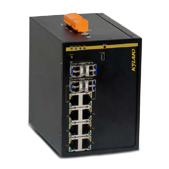
SICOM3010G User’s Manual-v1.0 3 Structure and Interface 3.1 Front Panel SICOM3010G-2GX/GE-6GE Figure 1 Front Panel 1 Table 1 SICOM3010G-2GX/GE-6GE Front Panel Number Diagram Label Description PWR1 Power 1 LED PWR2 Power 2 LED Running LED Ring Ring LED Reset... - Page 7 Alarm LED GX7/GE7, GX8/GE8 1000Base-X, 10/100/1000Base-T(X) Combo port GE1~GE6 10/100/1000Base-T(X) RJ45 port RJ45 port Speed LED RJ45 port Link/ACT LED SICOM3010G-2GX/GE-2GX-6GE Figure 2 Front Panel 2 Table 2 SICOM3010G-2GX/GE-2GX-6GE Front Panel Number Diagram Label Description PWR1 Power 1 LED...
-
Page 8: Top Panel
SICOM3010G User’s Manual-v1.0 PWR2 Power 2 LED Running LED Ring Ring LED Reset Reset button Console Console interface Alarm Alarm LED GX9, GX10 1000Base-X, 10/100/1000Base-T(X) SFP port GX7/GE7, GX8/GE8 1000Base-X, 10/100/1000Base-T(X) Combo port GE1~GE6 10/100/1000Base-T(X) RJ45 port RJ45 port Speed LED RJ45 port Link/ACT LED 3.2 Top Panel... -
Page 9: Mounting
SICOM3010G User’s Manual-v1.0 Figure 3 Top Panel Table 3 SICOM3010G Top Panel Number Description Power supply terminal block Grounding Screw Relay contact 4 Mounting 4.1 Dimension Drawing Dimension Drawing for DIN-Rail Mounting (Unit: mm) Figure 4 DIN-Rail Mounting Dimension... -
Page 10: Mounting Steps
Step 2: Insert the top of the DIN-Rail into the slot of the DIN-Rail connecting seat in the rear panel of SICOM3010G as shown below; move the switch in the direction of arrow 2 to put the whole Din-Rail into the seat; check whether SICOM3010G is firmly mounted on the DIN-Rail, as shown below. - Page 11 DIN-Rail and switch, as shown in arrow 1. Step 2: Pull the SICOM3010G up in the direction of arrow 2; meanwhile remove the switch from the DIN-Rail along the direction of arrow 3.
- Page 12 SICOM3010G User’s Manual-v1.0 then slide down SICOM3010G as seen below; finally screw 4 screws tightly. Now the SICOM3010G should be firmly fixed to the wall or cabinet. Figure 8 Panel Mounting Remove SICOM3010G from wall or cabinet The specific steps are as follows: Step 1: Use a screwdriver to loosen 4 screws;...
-
Page 13: Cable Connection
SICOM3010G User’s Manual-v1.0 5 Cable Connection 5.1 10/100/1000Base-T(X) Ethernet Port 10/100/1000Base-T(X) Ethernet RJ45 port can be connected to terminal equipment and network devices with straight-through cables or crossover cables. RJ45 connectors must be equipped at both ends of cable. Pin definition of 10/100/1000Base-T(X) RJ45 port Pin number of 10/100/1000Base-T(X) RJ45 port is shown in Figure 10. - Page 14 SICOM3010G User’s Manual-v1.0 Transmit/Receive Data(TRD3-) Transmit/Receive Data(TRD2-) Note: “+”“-”means level polarity. Wiring Sequence Figure 11 10/100/1000M Straight-through Cable Wiring Figure 12 10/100/1000M Cross-over Cable Wiring Note: The correlation between the pin of RJ45 connector and the color of twisted pair is: 1-orange and white, 2-orange, 3-green and white, 4-blue, 5-blue and white, 6-green, 7-brown and white, 8-white.
-
Page 15: 1000Base-X, 10/100/1000Base-T(X) Sfp Port
SICOM3010G User’s Manual-v1.0 5.2 1000Base-X, 10/100/1000Base-T(X) SFP Port 1000Base-X, 10/100/1000Base-T(X) SFP port namely is 1000Base SFP slot. Insert SFP module to SFP slot, and then plug the twisted pair or the optical fiber into SFP module to transmit data. Choose the model of SFP module to meet your requirements, as shown in Table 11. - Page 16 SICOM3010G User’s Manual-v1.0 Figure 14 Gigabit SFP Optical Module Wiring Confirm Gigabit SFP optical module RX port and TX port 1. Insert the two connectors in one end of optical fiber into SFP optical module, and then insert the two connectors in the other end of the optical fiber into SFP optical module of another switch to communicate.
-
Page 17: Gigabit Sfp Electrical Module
SICOM3010G User’s Manual-v1.0 Figure 15 SFP Optical Module 5.2.2 Gigabit SFP Electrical Module Figure 16 shows an example of a Gigabit SFP electrical module; Figure 16 Gigabit SFP Electrical Module The use of SFP electrical module While wiring, first insert the SFP electrical module into the SFP slot in the switch, and then plug the twisted pair into the SFP electrical module. -
Page 18: 1000Base-X, 10/100/1000Base-T(X) Combo Port
SICOM3010G User’s Manual-v1.0 Figure 17 SFP Electrical Module 5.3 1000Base-X, 10/100/1000Base-T(X) Combo Port As shown in Figure 18, The 1000Base-X, 10/100/1000Base-T(X) Combo port consists of one 1000 Base-X port (GX7) and one 10/100/1000Base-T(X) Ethernet port (GE7), and only one of the two ports can be used at one time. -
Page 19: Console Interface
SICOM3010G User’s Manual-v1.0 Figure 18 Combo Port 10/100/1000Base-T(X) Ethernet port The instructions of 10/100/1000Base-T(X) Ethernet port can refer to section 5.1. 1000Base-X port Insert Gigabit SFP optical module into 1000Base-X port, and then plug the optical fiber into SFP module to transmit data. Choose the model of SFP module that will meet your requirements, as shown in Table 11. -
Page 20: Power
SICOM3010G User’s Manual-v1.0 Table 5 Mini USB Pin Definition Mini USB Pin Definition VBUS USB connector USB connector pin number is shown in Figure 20. Figure 20 USB Connector USB pin definition is shown in Table 6. Table 6 USB Pin Definition... -
Page 21: Grounding
SICOM3010G User’s Manual-v1.0 and less than 2.5mm . The grounding resistance requirement: <5Ω. 5 pin 5.08mm power terminal block Figure 21 5-pin 5.08mm-spacing Plug-in Terminal Block Table 7 5 Pin 5.08mm Power Terminal Block Contact Definition Contact Number DC Wiring Definition... - Page 22 SICOM3010G User’s Manual-v1.0 Figure 22 Chassis Grounding and Power Terminal Grounding There is a grounding screw on the top panel of the SICOM3010G, which is for chassis ground. One end of the chassis grounding cable is connected with the grounding screw and the other end of the cable is reliably grounded.
-
Page 23: Relay Contact
SICOM3010G User’s Manual-v1.0 Figure 23 18#AWG Yellow-Green Line (Unit: mm) Note: If SICOM3010G needs to perform a dielectric voltage withstand test, in order to avoid test failure, please disconnect the 18#AWG yellow-green line to disable surge protection circuit that leads to leakage electricity. -
Page 24: Led Indicators
SICOM3010G User’s Manual-v1.0 Figure 25. Figure 25 3-Pin 5.08mm-Spacing Plug-In Terminal Blocks The electrical parameters of the relay: Max Switch Voltage: 250VAC/220VDC; Max Switch Current: 2A Max Switch Power: 60W Note: Pin 1 and pin 2 are normally-open contacts; pin 2 and pin 3 are normally-closed contacts. - Page 25 SICOM3010G User’s Manual-v1.0 CPU is running abnormally or the switch is starting. Blinking CPU is running normally (1HZ) CPU is not started up. Alarm LED System alarm Alarm No system alarm. Power LEDs Power 1 connects and operates normally. PWR1 Power 1 disconnects or operates abnormally.
-
Page 26: Reset Button
SICOM3010G User’s Manual-v1.0 7 Reset Button Reset button supports reboot and restoring default configuration. Push the reset button and hold for one second then release to reboot the switch. Hold the reset button down for five seconds then release to restore default configuration (including IP address) and reboot;... - Page 27 SICOM3010G User’s Manual-v1.0 Figure 26 Hyper Terminal 4. Build a new connection named “aa” Figure 27 New Connection 5. Select COM port as the connection type.
- Page 28 SICOM3010G User’s Manual-v1.0 Figure 28 Choose Port 6. Set the parameters of COM port (Bits per second: 115200, Data bits: 8, Parity: None, Stop bits: 1, Flow control: None) Figure 29 Set COM Parameters 7. Click “OK” to enter the CLI interface, and type in a CLI command from Table 9.
-
Page 29: Connected Through Ethernet Cable
SICOM3010G User’s Manual-v1.0 Management View SWITCH#show version Show version of switch Management View SWITCH#reboot Reboot Management View SWITCH#load default Restore default configuration (except for IP address) Management View SWITCH#config terminal Enter configuration view 8.2 Connected through Ethernet Cable 1. Connect any RJ45 port of the switch with the Ethernet port of a personal computer with a RJ45 cable. -
Page 30: Product Configuration Information
Figure 31, login with default user name “admin” and password “123”. Figure 31 Web Interface Access Screen Note: We recommend IE version 8.0 or greater. 9 Product Configuration Information The specific configuration models of SICOM3010G are shown in Table 10 Table 10 SICOM3010G Configuration Model Interface Description Power... - Page 31 SICOM3010G User’s Manual-v1.0 inputs Table 11 SICOM3010G Optional Accessories Model Description DT-BGAZ-02 Panel mounting kit DT-FCZ-RJ45-01 RJ45 dustproof shield DT-XL-Mini USB-USB-2m USB console cable, Mini USB to USB, 2m Gigabit SFP Module IGSFP-1000BASE-T-RJ45 1000Base-T(X) port, RJ45 connector IGSFP-10/100/1000BASE-T-RJ45 10/100/1000Base-T(X) port, RJ45 connector IGSFP-M-SX-LC-850-0.55...
-
Page 32: Basic Features And Specifications
10 Basic Features and Specifications Power Requirements Power input: 12DC (9~18VDC), 24AC/DCW (18~72VDC,18~50VAC) Power terminal: 5-pin 5.08mm-spacing plug-in terminal block Power consumption: SICOM3010G-2GX/GE-6GE: 10W (MAX) SICOM3010G-2GX/GE-2GX-6GE: 11.3W (MAX) Physical Characteristics Housing: Metal, fanless Installation: DIN-Rail or panel mounting Dimensions (W×H×D): 88mm×135mm×137mm...
Need help?
Do you have a question about the SICOM3010G and is the answer not in the manual?
Questions and answers