
Related Manuals for KYLAND Technology SICOM3000A


Summary of Contents for KYLAND Technology SICOM3000A
- Page 1 SICOM3000A Industrial Ethernet Switch Hardware Installation Manual Publication Data: Sep. 2017 Version: V1.0 No.: 112020149...
- Page 2 SICOM3000A Industrial Ethernet Switch Hardware Installation Manual Disclaimer: Kyland Technology Co., Ltd. tries to keep the content of this manual as accurate and as updated as possible. This document is not guaranteed to be error-free, and we reserve the right to amend it without notice to users.
- Page 3 Notice for Safety Operation The product performs reliably as long as it is used according to the guidance. Artificial damage or destruction of the device should be avoided. Before using the device, read this manual carefully for personal and equipment safety. Please keep the manual for further reference.
- Page 4 Do not disassemble the device by yourself. When an anomaly occurs, contact our sales or technical support personnel. If any part is lost, contact our sales or technical support personnel to purchase the substitute. Do not purchase parts from other channels. ...
-
Page 5: Table Of Contents
Contents 1 Product Overview .......................1 2 Structure and Interface .......................3 2.1 Front Panel ........................3 2.2 Top Panel ........................4 3 Mounting ..........................5 Dimension Drawing ......................5 3.1 ............................5 3.2 Mounting Modes and Steps ..................6 3.2.1 DIN-Rail Mounting ....................6 3.2.2 Panel Mounting ......................8 4 Connection ........................ -
Page 6: Product Overview
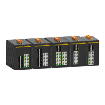
The series switches provide Mini USB Console port, and supports one-touch recovery, and network management through Web, Telnet, and console port. SICOM3000A supports DIN rail mounting and panel mounting. It provides two 100/1000Base-X, 10/100/1000Base-T(X) SFP slots (Gigabit SFP Slot), and eight 10/100Base-T(X) Ethernet ports, The SPF slots support the optical power detection function. - Page 7 Product Overview FC05=FC connector, 1310nm, 5km Ports with S: SC40=SC connector, 1310nm, 40km ST40=ST connector, 1310nm, 40km FC40=FC connector, 1310nm, 40km SC60=SC connector, 1310nm, 60km SC80=SC connector, 1550nm, 80km Ports without S or M: PS1-PS2: power input L3-L3 (24VDC, redundant power input) Note:...
-
Page 8: Structure And Interface
Structure and Interface 2 Structure and Interface Caution: It is recommended to purchase the port dustproof shield (optional) to keep ports clean and ensure device performance. 2.1 Front Panel Figure 1 Front Panel (1) Power 1 LED (2) Power 2 LED (3) Running LED (4) Ring LED (5) Alarm LED... -
Page 9: Top Panel
Structure and Interface 2.2 Top Panel Figure 2 Top Panel... -
Page 10: Mounting
Mounting 3 Mounting 3.1 Dimension Drawing Figure 3 Dimensions for DIN-Rail Mounting (unit: mm) Figure 4 Dimensions for DIN-Rail Mounting (unit: mm) Caution: As part of the heat dissipation system, the switch housing becomes hot during operation. -
Page 11: Mounting Modes And Steps
Mounting Please use caution when coming in contact and avoid covering the switch housing when the switch is running. The figures in this manual are only for reference. 3.2 Mounting Modes and Steps The device supports both DIN-rail mounting and panel mounting. Before installation, make sure that the following requirements are met. - Page 12 Mounting Figure 5 DIN-Rail 1 Mounting DIN-Rail 1 Dismounting Step 1: As shown in the following figure, press the device downward and move the device in direction 1 until the bottom of the device is detached from the DIN rail. Step 2: Pull the device upward and move the device in direction 2 until the device is removed from the DIN rail completely.
-
Page 13: Panel Mounting
Mounting Figure 7 DIN-Rail 2 Mounting DIN-Rail 2 Dismounting Step 1: Insert the head of a screwdriver into the opening of the spring locking piece at the bottom from the left. Lift the handle of the screwdriver to open the spring locking piece of the connecting seat, as shown on the left of the following figure. - Page 14 Mounting Mounting Step 1: Use screws to fix the plate for panel mounting to the rear panel of the device. Step 2: Select the mounting position (on a wall or inner wall of a cabinet) for the device and guarantee adequate space and heat dissipation for it.
- Page 15 Mounting Figure 10 Panel Dismounting Caution: Cut off the power and disconnect all cables before mounting, dismounting or moving the equipment.
-
Page 16: Connection
Connection 4 Connection 4.1 10/100Base-T(X) Ethernet Port 10/100Base-T(X) Ethernet port is equipped with RJ45 connector. The port is self-adaptive. It can automatically configure itself to work in 10M or 100M state, full or half duplex mode. The port can also adapt to MDI or MDI-X connection automatically. You can connect the port to a terminal or network device with a straight-through or cross-over cable. -
Page 17: 100Base-Fx Ethernet Port
Connection Figure 12 Connection Using Straight-through/Cross-over Cable Note: The color of the cable for RJ45 connector meets the 568B standard: 1-orange and white, 2-orange, 3-green and white, 4-blue, 5-blue and white, 6-green, 7-brown and white, and 8-brown. 4.2 100Base-FX Ethernet Port 100Base-FX Ethernet port is equipped with FC/ST/SC connector, and each port consists of TX (transmit) port and RX (receive) port. -
Page 18: 100/1000Base-X, 10/100/1000Base-T(X) Sfp Slot
Connection laser products. Routine operation is not harmful to your eyes, but do not look directly at the fiber port when the device is powered on. 4.3 100/1000Base-X, 10/100/1000Base-T(X) SFP slot 100/1000Base-X, 10/100/1000Base-T(X) SFP slot (gigabit SFP slot) requires an SFP optical/electrical module to enable data transmission. -
Page 19: Sfp Optical Module
Connection 4.3.1 SFP Optical Module Figure 14 SFP Optical Module An SFP optical module is equipped with LC connector, and each port consists of a TX (transmit) port and an RX (receive) port. To enable communication between Device A and Device B, connect the TX port of Device A to the RX port of Device B, and the RX port of Device A to the TX port of Device B, as shown in the following figure. -
Page 20: Sfp Electrical Module
Connection If the LED is on, the connection is correct. If the LED is off, the link is not connected. This may be caused by incorrect connection of the TX and RX ports. In this case, swop the two connectors at one end of the fibers. Caution: ... -
Page 21: Grounding
Connection (optional). The device provides the console port on the front panel. To use the console port, you need to install Mini USB driver.exe (you can find the program in the delivered CD) on the computer. One end of a USB console cable is Mini USB connector to be inserted into the console port of the switch, and the other end is the USB connector to be inserted into the USB port of a PC. -
Page 22: Power Terminal Block
Connection the switch properly. You need to ground the switch before it is powered on and disconnect the grounding cable after the switch is powered off. The switch provides a grounding screw(see Figure 2) on the top panel for chassis grounding. After crimping one end of the grounding cable to a cold pressed terminal, secure the end to the grounding screw and connect the other end to the earth firmly. - Page 23 Connection PGND PGND PWR2: - PWR2: N PWR2: + PWR2: L Wiring and Mounting Step 1: Ground the device properly according to section 4.5. Step 2: Remove the power terminal block from the device. Step 3: Insert the power wires into the power terminal block according to Table 5 and secure the wires.
-
Page 24: Alarm Terminal Block
Connection Do not remove any part or plug in or out any connector when the device is powered on. 4.7 Alarm Terminal Block The device provides an alarm terminal block on the top panel for alarm output. When the switch works properly, the normally-open contacts of the alarm relay are closed and the normally-closed contacts are open;... - Page 25 Connection Step 3: Insert the alarm terminal block into its socket. Wiring and Mounting should meet following specifications. Table 7 Wiring and Mounting Specifications Terminal Type Required Torque Wire Range (AWG) Terminal Block Plug 4.5-5.0 lb-in 12-24...
-
Page 26: Reset
Reset 5 Reset The device provides a Reset button on the front panel. The button can be used to restart the device or restore factory default settings. You can restart the device by pressing and holding the button for 0.5 to 3 second. You can restore factory default settings by pressing and holding the button for 3 seconds or more. -
Page 27: Leds
LEDs 6 LEDs Table 8 Front Panel LEDs State Description Power 1 is connected and operates properly. Power 1 LED Power 1 is not connected or operates abnormally. Power 2 is connected and operates properly. Power 2 LED Power 2 is not connected or operates abnormally. Blinking The CPU operates properly. -
Page 28: Switch Access
Switch Access 7 Switch Access You can access the switch in any of the following ways: 7.1 Access through Console Port Step 1: Install Mini USB driver.exe. You can find the program in the delivered CD. Connect the USB port of the PC to the console port of the switch with the USB console cable. Step 2: Open Hyper Terminal in Windows OS. - Page 29 Switch Access Figure 25 Selecting a Serial Port Note: To confirm the communication port in use, right-click [My Computer] and select [Property]. Click [Hardware] → [Device Manager] → [Port] to view the communication port. Step 5: Set port parameters (Bits per second: 115200, Data bits: 8, Parity: None, Stop bits: 1, and Flow control: None), as shown in the following figure.
-
Page 30: Access Through Telnet
Switch Access Figure 26 Setting Port Parameters Step 6: Click OK to enter the switch CLI. Then the following commands can be used to perform operations. Table 9 CLI Commands View Command Description Privileged mode SWITCH#show interface vlan 1 Query the IP address of the switch. Privileged mode SWITCH#show version Query the version of the switch. -
Page 31: Access Through Web
Switch Access IP address of the device), enter "telnet 192.168.0.2" in the dialog box. Figure 27 Access through Telnet Step 3: Click OK. The Telnet CLI is displayed. Then you can run the commands in Table 9 to perform operations. 7.3 Access through Web Step 1: Connect the network port of a PC to the Ethernet port of the switch with a network cable. -
Page 32: Basic Features And Specifications
Basic Features and Specifications 8 Basic Features and Specifications Power Requirements Maximum Voltage Power Identifier Rated Voltage Range Range 24VDC 18-36VDC Terminal block 5-pin 5.08mm-spacing plug-in terminal block Rated Power Consumption Rated power consumption 9W (MAX) Physical Characteristics Housing Metal, fanless Protection class IP30 Installation... - Page 33 FAX: +86-10-88796678 Website: http://www.kyland.com Email: support@kyland.com For more information about KYLAND products, please visit our website: http://www.kyland.com...
Need help?
Do you have a question about the SICOM3000A and is the answer not in the manual?
Questions and answers