
Related Manuals for KYLAND Technology SICOM3000A


Summary of Contents for KYLAND Technology SICOM3000A
- Page 1 SICOM3000A Industrial Ethernet Switch Hardware Installation Manual Publication Data: Mar. 2019 Version: V1.2 No.: 112020167...
- Page 2 SICOM3000A Industrial Ethernet Switch Hardware Installation Manual Disclaimer: Kyland Technology Co., Ltd. tries to keep the content of this manual as accurate and as updated as possible. This document is not guaranteed to be error-free, and we reserve the right to amend it without notice to users.
- Page 3 Notice for Safety Operation The product performs reliably as long as it is used according to the guidance. Artificial damage or destruction of the device should be avoided. Before using the device, read this manual carefully for personal and equipment safety. Please keep the manual for further reference.
- Page 4 Do not disassemble the device by yourself. When an anomaly occurs, contact our sales or technical support personnel. If any part is lost, contact our sales or technical support personnel to purchase the substitute. Do not purchase parts from other channels. ...
- Page 5 NOTE: This equipment has been tested and found to comply with the limits for a Class A digital device, pursuant to part 15 of the FCC Rules. These limits are designed to provide reasonable protection against harmful interference when the equipment is operated in a commercial environment.
-
Page 6: Table Of Contents
Contents 1 Product Overview .......................1 1.1 Small products(The shell width is 66 mm) ...............1 1.2 Medium products(The shell width is 88 mm) ............2 1.3 Large products(The shell width is 102 mm) .............1 2 Structure and Interface .......................3 2.1 Front Panel ........................3 2.2 Top Panel ........................6 2.2.1 Low voltage(L2/L5)products Top Panel ............6 2.2.2 High voltage(HV)products Top Panel ...............7... - Page 7 6 LEDs ..........................27 7 Switch Access ........................28 7.1 Access through Console Port ..................28 7.2 Access through Telnet ....................30 7.3 Access through Web ....................31 8 Basic Features and Specifications ..................32...
-
Page 8: Small Products(The Shell Width Is 66 Mm
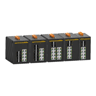
Product Overview 1 Product Overview SICOM3000A includes a series of green low-consumption industrial Ethernet switches. The series switches provide RJ45 Consoleport, and supports one-touch recovery, and network management through Web, Telnet, and console port. 1.1 Small products(The shell width is 66 mm)... -
Page 9: Medium Products(The Shell Width Is 88 Mm
(Gigabit SFP Slot), and eight 10/100/1000Base-T(X) Ethernet ports, or eight 10/100/1000Base-T(X) Ethernet ports. The SPF slots support the optical power detection function. For details, see the following table. Table 2 Models Models SICOM3000A-Ports-Connector-PS1-PS2 Code Code option 4GX8GE、2GX8GE、8GE : Notes ,... -
Page 10: Product Overview
100/1000Base-X, 10/100/1000Base-T(X) SFP slots (Gigabit SFP Slot), and sixteen 10/100/1000Base-T(X) Ethernet ports. The SPF slots support the optical power detection function. For details, see the following table. Table 3 Models Models SICOM3000A-Ports-Connector-PS1-PS2 Code Code option 12GX8GE、 8GX8GE、 8GX8T、 8SFP8T、 4GX16GE、 4GX16T、 4SFP16T、 2GX16GE、2GX16T、16GE、16T :... - Page 11 Product Overview een 10/100/1000Base-T(X)ports : , ; 2GX16T two 100/1000Base-X 10/100/1000Base-T(X) SFPslots sixteen 10/100Base-T(X)ports : 16GE sixteen 10/100/1000Base-T(X)ports : sixteen 10/100Base-T(X)ports Connector:parameters for Ports can’t work at 100Base-FX in the default,sfp slots support configure the 100Base-FX L2-L2 (24-48VDC, redundant power input) L5-L5 (12-24VDC, redundant power input) PS1-PS2:power input HV:100-240VAC,50/60Hz;110-220VDC...
-
Page 12: Structure And Interface
Structure and Interface 2 Structure and Interface Caution: It is recommended to purchase the port dustproof shield (optional) to keep ports clean and ensure device performance. 2.1 Front Panel Small product front panel Figure 1 Medium product front panel (1) Power 1 LED (2) Power 2 LED (3) Running LED... - Page 13 Structure and Interface (11) 10/100/1000Base-X SFP Slot (12) 10/100Base-X Ethernet Port (13) 10/100Base-T(X) Ethernet Port speed LED (yellow) (14) 10/100Base-T(X) Ethernet Port connection status LED (green) Medium product front panel Figure 2 Medium product front panel (1) Power 1 LED (2) Power 2 LED (3) Running LED (4) Ring LED...
- Page 14 Structure and Interface (12) 10/100/1000Base-T(X) Ethernet Port (13) 10/100/1000Base-T(X) Ethernet Port speed LED (yellow) (14) 10/100/1000Base-T(X) Ethernet Port connection status LED (green) Large product front panel Figure 3 Large product front panel (1) Power 1 LED (2) Power 2 LED (3) Running LED (4) Ring LED (5) Alarm LED...
-
Page 15: Top Panel
Structure and Interface (13) 10/100Base-T(X) or 10/100/1000Base-T(X) Ethernet Port connection status LED (green) (14) 100/1000M SFP Slot 2.2 Top Panel 2.2.1 Low voltage(L2/L5)products Top Panel Figure 4 Low voltage products Top Panel... -
Page 16: High Voltage(Hv)Products Top Panel
Structure and Interface 2.2.2 High voltage(HV)products Top Panel Figure 5 High voltage products Top Panel... -
Page 17: Mounting
Mounting 3 Mounting 3.1 Dimension Drawing Figure 6 Dimensions for Small Products DIN-Rail Mounting (unit: mm) Figure 7 Dimensions for Small Products Panel Mounting(unit: mm) - Page 18 Mounting Figure 8 Dimensions for Medium Products DIN-Rail Mounting (unit: mm) Figure 9 Dimensions for Medium Products Panel Mounting(unit: mm)
-
Page 19: Mounting Modes And Steps
Mounting Figure 10 Dimensions for Large Products DIN-Rail Mounting (unit: mm) Figure 11 Dimensions for Large Products Panel Mounting(unit: mm) Caution: As part of the heat dissipation system, the switch housing becomes hot during operation. Please use caution when coming in contact and avoid covering the switch housing when the switch is running. -
Page 20: Din-Rail Mounting
Mounting non-condensing) 2) Power requirement: The power input is within the voltage range of the switch. 3) Grounding resistance: <5 4) No direct sunlight, distant from heat source and areas with strong electromagnetic interference. 5) Devices are to be installed in an authority certified enclosure and accessible only by the use of a tool. -
Page 21: Panel Mounting
Mounting connecting seat, as shown on the left of the following figure. Step 2: Move the device in direction 2 until the bottom of the device is detached from the DIN rail. Then move the device in direction 3 and uplift the device until the top of the connecting seat is detached from the DIN rail. - Page 22 Mounting direction 1 until the four screws are in the Ф4 positions. Then tighten the screws to complete mounting. Figure 14 Panel Mounting Dismounting Step 1: Loosen the four screws with a screwdriver. Move the device upward until the four screws are in the Ф6.5 positions in the following figure.
- Page 23 Mounting Caution: Cut off the power and disconnect all cables before mounting, dismounting or moving the equipment.
-
Page 24: Connection
Connection 4 Connection 4.1 10/100Base-T(X) Ethernet Port 10/100Base-T(X) Ethernet port is equipped with RJ45 connector. The port is self-adaptive. It can automatically configure itself to work in 10M or 100M state, full or half duplex mode. The port can also adapt to MDI or MDI-X connection automatically. You can connect the port to a terminal or network device with a straight-through or cross-over cable. -
Page 25: 10/100/1000Base-T(X) Ethernet Port
Connection Figure 17 Connection Using Straight-through/Cross-over Cable Note: The color of the cable for RJ45 connector meets the 568B standard: 1-orange and white, 2-orange, 3-green and white, 4-blue, 5-blue and white, 6-green, 7-brown and white, and 8-brown. 4.2 10/100/1000Base-T(X) Ethernet Port 10/100/1000Base-T(X) Ethernet port is equipped with RJ45 connector. - Page 26 Connection Table 5 Pin Definitions of 10/100Base-T(X) Ethernet Port MDI-X Signal MDI Signal Receive Data+ (RD0+) Transmit Data+ (TD0+) Receive Data- (RD1-) Transmit Data- (TD1-) Transmit Data+ (TD0+) Receive Data+ (RD0+) Receive Data+ (RD2+) Transmit Data+ (TD2+) Receive Data- (RD2-) Transmit Data- (TD2-) Transmit Data- (TD1-) Receive Data- (RD1-)
-
Page 27: 100/1000Base-X, 10/100/1000Base-T(X) Sfp Slot
Connection 4.3 100/1000Base-X, 10/100/1000Base-T(X) SFP slot 100/1000Base-X, 10/100/1000Base-T(X) SFP slot (gigabit SFP slot) requires an SFP optical/electrical module to enable data transmission. The following table lists the SFP optical/electrical modules (optional) supported by the series switches. Table 6 SFP Optical/Electrical Modules Central Transmission Model... -
Page 28: Sfp Optical Module
Connection technical support personnel. 4.3.1 SFP Optical Module Figure 20 SFP Optical Module An SFP optical module is equipped with LC connector, and each port consists of a TX (transmit) port and an RX (receive) port. To enable communication between Device A and Device B, connect the TX port of Device A to the RX port of Device B, and the RX port of Device A to the TX port of Device B, as shown in the following figure. -
Page 29: Sfp Electrical Module
Connection other end into the peer module. 2. View the corresponding connection status LED: If the LED is on, the connection is correct. If the LED is off, the link is not connected. This may be caused by incorrect connection of the TX and RX ports. In this case, swop the two connectors at one end of the fibers. -
Page 30: Console Port
Connection 4.4 Console Port 4.4.1 RJ45 Console port Medium products& Large products provide RJ45 Console port. There is a Console port on the front panel of the switch, as shown in Connect the 9-pin serial port of a PC to the console port of the switch with a DB9-RJ45 console cable. -
Page 31: Grounding
Connection TXD (Transmit data) RXD (Receive data) GND (Grounding) GND (Grounding) 4.5 Grounding Grounding protects the switch from lightning and interference. Therefore, you must ground the switch properly. You need to ground the switch before it is powered on and disconnect the grounding cable after the switch is powered off. - Page 32 Connection power wires to the terminal block to provide power to the device. The device supports redundant power input with a 5-pin 5.08mm-spacing plug-in terminal block. When one power input is faulty, the device can continue operating properly, thereby improving network reliability.
-
Page 33: Alarm Terminal Block
Connection the device. Step 5: Connect the other end of the power wires to the external power supply system according to the power supply requirements of the device. View the status of the power LEDs on the front panel. If the LEDs are on, the power is connected properly. Wiring and Mounting should meet following specifications. - Page 34 Connection Figure 29 Alarm Terminal Block (socket) Electrical parameters of the relay: Max Switch Voltage: 24VDC; Max Switch Current: 1A Max Switching Power: 60W Dielectric Strength: 2KV Note: Pin 1 and pin 2 are normally-open contacts; pin 2 and pin 3 are normally-closed contacts. When the switch works properly, pin 1 and pin 2 are closed, pin 2 and pin 3 are open;...
-
Page 35: Reset
Reset 5 Reset The device provides a Reset button on the front panel. The button can be used to restart the device or restore factory default settings. You can restart the device by pressing and holding the button for 0.5 to 3 second. You can restore factory default settings by pressing and holding the button for 3 seconds or more. -
Page 36: Leds
LEDs 6 LEDs Table 12 Front Panel LEDs State Description Power 1 is connected and operates properly. Power 1 LED Power 1 is not connected or operates abnormally. Power 2 is connected and operates properly. Power 2 LED Power 2 is not connected or operates abnormally. Blinking The CPU operates properly. -
Page 37: Switch Access
LEDs Effective port connection 10/100Base-T(X) Ethernet port Blinking Ongoing network activities connection status LED (green) No effective port connection 10/100Base-T(X) Ethernet port 1000M working state (1000Base-T(X)) speed LED (yellow) 10M or 100M working state or no connection Effective port connection 10/100Base-T(X) Ethernet port Blinking Ongoing network activities... - Page 38 Switch Access Figure 30 Creating a Connection Step 4: Connect the communication port in use, as shown in the following figure. Figure 31 Selecting a Serial Port Note: To confirm the communication port in use, right-click [My Computer] and select [Property]. Click [Hardware] →...
-
Page 39: Access Through Telnet
Switch Access Figure 32 Setting Port Parameters Step 6: Click OK to enter the switch CLI. Then the following commands can be used to perform operations. Table 13 CLI Commands View Command Description Privileged mode SWITCH#show interface vlan 1 Query the IP address of the switch. Privileged mode SWITCH#show version Query the version of the switch. -
Page 40: Access Through Web
Switch Access address of the device), enter "telnet 192.168.0.2" in the dialog box. Figure 33 Access through Telnet Step 3: Click OK. The Telnet CLI is displayed. Then you can run the commands (as shown inTable 13) to perform operations. 7.3 Access through Web Step 1: Connect the network port of a PC to the Ethernet port of the switch with a network cable. -
Page 41: Basic Features And Specifications
Basic Features and Specifications 8 Basic Features and Specifications Power Requirements Maximum Voltage Power Identifier Rated Voltage Range Range 24-48VDC 18-60VDC 12-24VDC 9-36VDC 100-240VAC,50/60Hz;110-220VDC 85-264VAC/77-300VDC L2/L5:5-pin 5.08 mm-spacing plug-in terminal block Terminal block HV:3-pin 7.62 mm-spacing plug-in terminal block Rated Power Consumption Small products:<12W Rated power Medium products:<16W... - Page 42 Basic Features and Specifications Operating temperature -40℃~+75℃ Storage temperature -40℃~+85℃ Ambient relative humidity 5%~95% (non-condensing) Pollution degree Altitude 2000m Warranty Warranty 5 years...
- Page 43 FAX: +86-10-88796678 Website: http://www.kyland.com Email: support@kyland.com For more information about KYLAND products, please visit our website: http://www.kyland.com...
Need help?
Do you have a question about the SICOM3000A and is the answer not in the manual?
Questions and answers