
Subscribe to Our Youtube Channel
Related Manuals for IBASE Technology CMI203-990


Summary of Contents for IBASE Technology CMI203-990
- Page 1 CMI203 System Family Mini-ITX Standard Systems User’s Manual Version 1.0 (Mar. 2018)
- Page 2 No part of this publication may be reproduced, copied, stored in a retrieval system, translated into any language or transmitted in any form or by any means, electronic, mechanical, photocopying, or otherwise, without the prior written consent of IBASE Technology, Inc. (hereinafter referred to as “IBASE”).
-
Page 3: Compliance
Compliance This product has passed CE tests (pre-scan) for environmental specifications and limits. This product is in accordance with the directives of the Union European (EU). If users modify and/or install other devices in this equipment, the CE conformity declaration may no longer apply. This product has been tested and found to comply with the limits for a Class B (pre- scan) device, pursuant to Part 15 of the FCC Rules. -
Page 4: Important Safety Information
Important Safety Information Carefully read the precautions before using the device. Environmental conditions: • Lay the device horizontally on a stable and solid surface in case the device may fall, causing serious damage. • Leave plenty of space around the device and do not block the openings for ventilation. -
Page 5: Caution
CAUTION Replace only with the same or equivalent type recommended by the manufacturer. Dispose of used batteries according to the manufacturer’s instructions. Warranty Policy • IBASE standard products: 24-month (2-year) warranty from the date of shipment. If the date of shipment cannot be ascertained, the product serial numbers can be used to determine the approximate shipping date. -
Page 6: Table Of Contents
Technical Support & Services ..............v Chapter 1 General Information ..............1 Introduction ..................... 2 Features ....................2 Specifications – CMI203-991 & CMI203-990 ........... 3 Specifications – CMI203-982 & CMI203-981 ........... 5 Overview ....................7 Dimensions ................... 10 Chapter 2 Hardware Installation ............ -
Page 7: Chapter 1 General Information
Chapter 1 General Information The information provided in this chapter includes: • Features • Specifications • Overview • Dimensions... -
Page 8: Introduction
– MI991, MI990, MI982 and MI981. These motherboards feature iSmart that allows the device capable of auto-scheduling for general applications and gives energy savings on power. The system family and the compatible motherboards are listed as below. Model CMI203-991 CMI203-990 CMI203-982 CMI203-981 Motherboard MI991 MI990... -
Page 9: Specifications - Cmi203-991 & Cmi203-990
General Information 1.3 Specifications – CMI203-991 & CMI203-990 Product Name CMI203-991 CMI203-990 System Motherboard MI991AF MI991EF MI990VF MI990EF ® ® Intel Gen. Core™ i7/i5/i3 Intel Gen. Core™ i7/i5/i3 ® ® ® ® / Pentium / Celeron / Pentium / Celeron... - Page 10 Product Name CMI203-991 CMI203-990 I/O Ports Front Panel • 1 x AC power inlet • 4 x COM ports (plus 1 reserved hole) • 1 x DVI-D • 1 x HDMI • 1 x DisplayPort • Rear Panel 6 x USB 3.0 •...
-
Page 11: Specifications - Cmi203-982 & Cmi203-981
General Information 1.4 Specifications – CMI203-982 & CMI203-981 Product Name CMI203-982 CMI203-981 System Motherboard MI982EF MI981AF ® Intel Gen. Core™ i7/i5/i3 ® ® / Pentium / Celeron DT Processor ® ® Chipset Intel H81 PCH Intel Q87 PCH 2 x DDR3L-1600 SO-DIMM, 2 x DDR3L-1600 SO-DIMM, Memory upgradable to 16 GB... - Page 12 Product Name CMI203-982 CMI203-981 I/O Ports Front Panel • 1 x AC power inlet • 4 x COM ports (plus 1 reserved hole) • 1 x DVI-D • 1 x VGA • 1 x DisplayPort • Rear Panel 6 x USB 3.0 •...
-
Page 13: Overview
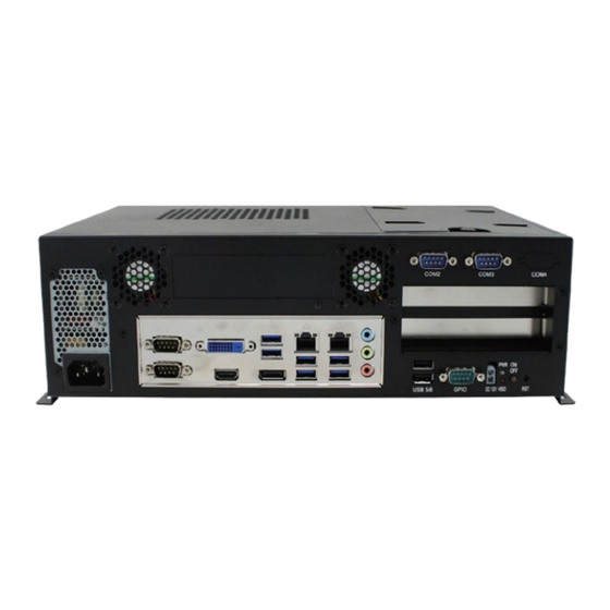
General Information 1.5 Overview Front View No. Name Name 2.5” / 3.5” HDD Drive Bay Wall Mount Brackets CMI203 System Family User Manual... - Page 14 Rear View CMI203-991 & CMI221-990: No. Name Name COM Ports GPIO Port (COM4 is reserved) LCM Slot (Reserved) USB 2.0 Ports Audio Jacks GbE LAN Ports (From top to bottom: Line-In, Line-Out, Mic-In) PCIe (x16) Expansion Slots USB 3.0 Ports Reset Button DisplayPort Power Button...
- Page 15 General Information CMI203-982 & CMI221-981: No. Name Name COM Ports GPIO Port (COM4 is reserved) LCM Slot (Reserved) USB 2.0 Ports Audio Jacks GbE LAN Ports (From top to bottom: Line-In, Line-Out, Mic-In) PCIe (x16) Expansion Slots USB 3.0 Ports Reset Button DisplayPort Power Button...
-
Page 16: Dimensions
1.6 Dimensions Unit: mm CMI203 System Family User Manual... -
Page 17: Chapter 2 Hardware Installation
Chapter 2 Hardware Installation The information provided in this chapter includes: • Essential installations: memory and HDD • Expansion card , fan, and wall mount installation... -
Page 18: Essential Installations Before You Begin
2.1 Essential Installations Before You Begin 2.1.1 Memory Installation If you need to install or replace a memory module, disassemble the device cover first and then follow the instructions below for installation. Loosen 6 screws from the device cover and remove the cover. Press the ejector tab of the memory slot down and outwards with your fingertips. -
Page 19: Hdd Installation
Appendix 2.1.2 HDD Installation If you are using a model type of CMI203 System that doesn’t include a HDD, you will need to install one. Follow the instructions below for HDD installation or replacement. Loosen the screw from the HDD tray and open the tray up. Loosen 4 screws, attach your HDD, tighten these screws to fix the HDD and connect the related cables to the motherboard. -
Page 20: Pcie (X16) Expansion Card Installation
2.2 PCIe (x16) Expansion Card Installation Loosen 6 screws from the device cover and remove the cover. Remove the screw(s) to take out the expansion slot filler(s). Screws Expansion Slot Filler Install your PCIe (x16) expansion card and fix the card by tightening the screw mentioned above. -
Page 21: Fan Replacement
Appendix 2.3 Fan Replacement Remove 6 screws from the device cover and remove the cover. Remove 4 screws for a fan for replacement and tighten the screws after installation. 4 screws 4 screws After installation, tighten 6 screws mentioned in Step 1 to secure the device cover. -
Page 22: Mounting Brackets Installation
2.4 Mounting Brackets Installation Requirements Before mounting the system, ensure that you have enough room for the power adaptor and signal cable routing, and have good ventilation for the power adaptor. The method of mounting must be able to support the weight of the SE-102-N plus the weight of the suspending cables attached to the system.
Need help?
Do you have a question about the CMI203-990 and is the answer not in the manual?
Questions and answers