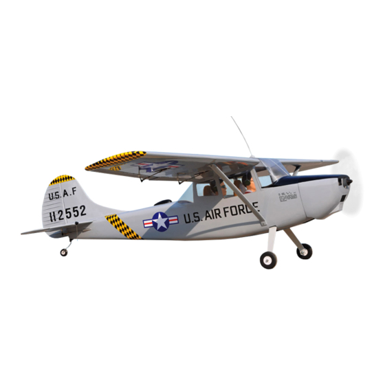
Black Horse Model BIRD DOG Instruction Manual Book
95% almost ready to fly, wingspan: 1,890mm. 74.41 in., length: 1,400mm. 55.12 in., weight: 3.5kg. 7.7lbs., part listing required not included, glow engine: 55-61 2 stroke./91 4 stroke, electric motor: kms 4120/05, battery: 4-5 cells-li-poly-14.8-18.5v-5.0
Table of Contents
Advertisement
Quick Links
SPECIFICATION
Wingspan : 1,890mm.
Length
: 1,400 mm.
Weight
:
3.5kg.
Part listing required (not included)
Glow Engine : 55 - 61 2 stroke.
91
Instruction Manual book
74.41 in.
Electric Motor: KMS 4120/05
Battery: 4-5 Cells-Li-Poly-14.8-18.5v- 5.000 mAh - 20 c .
55.12in.
Radio:
7.7lbs.
Servo :
4 stroke.
05 channels.
06-07 servos.
Made in Vietnam.
Advertisement
Table of Contents

Subscribe to Our Youtube Channel
Related Manuals for Black Horse Model BIRD DOG


Summary of Contents for Black Horse Model BIRD DOG
- Page 1 Instruction Manual book SPECIFICATION Wingspan : 1,890mm. 74.41 in. Electric Motor: KMS 4120/05 Battery: 4-5 Cells-Li-Poly-14.8-18.5v- 5.000 mAh - 20 c . Length : 1,400 mm. 55.12in. Radio: 05 channels. Weight 3.5kg. 7.7lbs. Servo : 06-07 servos. Part listing required (not included) Glow Engine : 55 - 61 2 stroke.
-
Page 2: Parts List
Instruction Manual Item code:BH82 . This instruction manual is designed to help you build a great flying aeroplane. Please read this manual thoroughly before starting assembly of your BIRD DOG. Use the parts listing below to identify all parts. WARNING Please be aware that this aeroplane is not a toy and if assembled or used incorrectly it is capable of causing injury to people or property. -
Page 3: Safety Precaution
BIRD DOG - INSTRUCTION MANUAL Item code:BH82. Caution: this model is not a toy! SAFETY PRECAUTION. If you are a beginner to this type of powered + This is not a toy model, please ask an experienced model flyer + Be sure that no other flyers are using your for help and support. -
Page 4: Installing The Aileron Servos
BIRD DOG - Instruction Manual Item code:BH82 . C/A glue Aileron C/A glue 1. Elevator plastic light. 2 .Plastic part for fuselage. 3 .Plastic for fuselage top hatch. 4. Wheels. 5. Fuel tank. . 6. Aluminium landing gear. 7. Tail gear set. - Page 5 BIRD DOG - INSTRUCTION MANUAL Item code:BH82. 2. Using a modeling knife, remove the cov- ering servo tray. C/A glue Remove covering Servo tray. Aileron Flap 1) Install the rubber grommets and brass eyelets onto the aileron servos. 3. Using the thread as a guide and using masking tape, tape the servo lead to the end of the thread: carefully pull the thread out.
- Page 6 BIRD DOG - Instruction Manual Item code:BH82 . Nilon control clasp 3mm x 40mm. M3 lock nut. 5. Instal servo tray with aileron servo into the wing as same as picture below. 2x10mm. Secure 2.INSTALLING THE AILERON CONTROL HORN. Drill a hole 3mm...
-
Page 7: Installing The Flap Servos
BIRD DOG - INSTRUCTION MANUAL Item code:BH82. II. FLAP. 1.INSTALLING THE FLAP SERVOS. Control horn of the aileron thread Repeat the procedure for the other wing half. 3.INSTALLING THE AILERON Electric way LINKAGES. Installing the aileron linkages as pictures below. - Page 8 BIRD DOG - Instruction Manual Item code:BH82 . Flap control horn. 3.INSTALLING THE FLAP Nilon control clasp LINKAGES. Installing the aileron linkages as pictures below. 90mm 3mm x 40mm. M3 lock nut. M2 lock nut C/A glue C/A glue Repeat the procedure for the other wing...
- Page 9 BIRD DOG - INSTRUCTION MANUAL Item code:BH82. THERE ARE TWO OPTIONS: 1. ELECTRIC MOTOR 2. ENGINE MOUNT. OPTION 1: ELECTRIC MOTOR Secure INSTALLING ELECTRIC MOTOR. 3 x 15mm 3 x 15mm Motor. Drill a hole 3mm diameter. C/A glue Epoxy glue...
- Page 10 BIRD DOG - Instruction Manual Item code:BH82 . C/A glue INSTALLING THE RECEIVER AND BATTERY. 3 x 15mm 1. Plug the servo leads and the switch lead into the receiver. You may want to plug an aileron extension into the receiver to make plugging in the aileron servo lead easier when you are installing the wing .
-
Page 11: Installing The Engine Mount
BIRD DOG - INSTRUCTION MANUAL Item code:BH82. Front view. COWLING. INSTALLING THE ENGINE MOUNT. 1) Slide the cowl over the motor and line See pictures below: up the back edge of the cowl with the marks you made on the fuselage. - Page 12 BIRD DOG - Instruction Manual Item code:BH82 . When the stopper assembly is installed in the tank, the top of the vent tube should rest just below the top surface of the tank. It should not touch the top of the tank.
- Page 13 BIRD DOG - INSTRUCTION MANUAL Item code:BH82. 9) To secure the fuel tank in place, ap- ply a bead of silicon sealer to the forward area of the tank, where it exits the fuselage behind the engine mounting box and to the rear of the tank at the forward bulkhead.
-
Page 14: Installing The Engine
BIRD DOG - Instruction Manual Item code:BH82 . INSTALLING THE ENGINE. 2.5 x25mm. Locate the long piece of wire used for the throttle pushrod. One end of the wire has been pre-bend in to a “Z” bend at the factory. This “Z”... - Page 15 BIRD DOG - INSTRUCTION MANUAL Item code:BH82. COWLING. 1) Slide the fiberglass cowl over the en- gine and line up the back edge of the cowl with Bottom side the marks you made on the fuselage. Trim and cut Trim and cut...
- Page 16 BIRD DOG - Instruction Manual Item code:BH82 . Throttle servo Machine screw Right side Front view Secure INSTALLING THE THROTTLE PUSHROD. Install one adjustable metal connector through the third hole out from the center of one servo arm, enlarge the hole in the servo arm using a 2mm drill bit to accommodate the servo connector.
- Page 17 BIRD DOG - INSTRUCTION MANUAL Item code:BH82. HORIZONTAL STABILIZER, VESTICAL INSTALLATION. Horizontal stabilize installation . See picture below. Top side C/A glue C/A glue C/A glue C/A glue...
- Page 18 BIRD DOG - Instruction Manual Item code:BH82 . C/A glue Epoxy glue C/A glue 1. Draw a center line onto the horizontal stabilizer. Then slide the horizontal into the fuselage. C/A glue center line 2 Using a modeling knife, cut away the covering from the fuselage for the stabilizer and remove it.
- Page 19 BIRD DOG - INSTRUCTION MANUAL Item code:BH82. Check to mark sure the wing and stabi- lizer are paralell. If they are not, lightly sand the opening in the fuselage for the stabilizer until the stabilizer is paralell to the wing.
- Page 20 BIRD DOG - Instruction Manual Item code:BH82 . C/A glue C/A glue ELEVATOR CONTROL HORN PUSHROD INSTALLATION. Elevator control horn install as same as the way of aileron control horn. Please see pic- tures below. M3 lock nut. 3mm x 40mm.
- Page 21 BIRD DOG - INSTRUCTION MANUAL Item code:BH82. C/A glue Elevator control horn ELEVATOR AND RUDDER PUSHROD INSTALLATION. Elevator and rudder pushrod install as same as the way of aileron pushrod. M2 lock nut. M2 lock nut C/A glue...
- Page 22 BIRD DOG - Instruction Manual Item code:BH82 . Vertical stabilizer installation See picture below. C/A glue 1) Using a modeling knife, remove the covering from the top of the fuselage and the covering from over the precut hinge slot cut...
-
Page 23: Mounting The Tail Wheel Bracket
BIRD DOG - INSTRUCTION MANUAL Item code:BH82. MOUNTING THE TAIL WHEEL BRACKET. Mark line 3 x 15mm 4. Now, remove the rudder and using a modeling knife, carefully cut just inside the 1. Set the tail wheel assembly in place marked lines and remove the film of the rud- on the plywood plate. - Page 24 BIRD DOG - Instruction Manual Item code:BH82 . Epoxy glue Epoxy glue C/A glue C/A glue Epoxy glue C/A glue Epoxy glue...
-
Page 25: Rudder Control Horn Installa- Tion
BIRD DOG - INSTRUCTION MANUAL Item code:BH82. RUDDER CONTROL HORN INSTALLA- TION. Rudder control horn install as same as the way of aileron control horn. Please see pic- tures below. M3 lock nut. 3mm x 40mm. Nilon control clasp Control horn of elevator. - Page 26 BIRD DOG - Instruction Manual Item code:BH82 . C/A glue Rudder Elevator pushrod. pushrod Secure MAIN GEAR INSTALATION. PARTS REQUIRED 1) Assemble and mounting the wheel pants as shown in the following pictures. Secure 2) Using the hardware provided, mount...
-
Page 27: Installing The Switch
BIRD DOG - INSTRUCTION MANUAL Item code:BH82. INSTALLING THE SWITCH. 1) Cut out the switch hole using a modeling knife. Use a 2mm drill bit and drill out the two mounting holes through the fuselage side. 2) Secure the switch in place using the two machine screws provided with the radio system. -
Page 28: Wing Attachment
BIRD DOG - Instruction Manual Item code:BH82 . Battery Receiver WING ATTACHMENT. Wing bolt. Locate the aluminium wing dihedral brace. Secure the wing and fuselage through wing bolt as picture below. Secure. *** Test fit the aluminium tube dihedral brace into each wing haft. -
Page 29: Plastic Parts
BIRD DOG - INSTRUCTION MANUAL Item code:BH82. 4x 30mm Insert and Secure secure Left wing Mark point Secure Plastic parts Plastic parts fuselage top hatch. C/A glue... - Page 30 BIRD DOG - Instruction Manual Item code:BH82 . Mark point Drill a hole 1mm diameter C/A glue Plastic parts of elevator Plastic parts of top fuselage Cut. Mark line. Remove covering...
- Page 31 BIRD DOG - INSTRUCTION MANUAL Item code:BH82. C/A glue Secure Mark point Secure Drill a hole 1mm diameter WING TRUTS INSTALLATION 3 x15mm...
-
Page 32: Control Throws
4) Check the control surface. 5) Check the receiver antenna . It should be fully extended and not coiled up inside the fuselage. 6) Properly balance the propeller. We wish you many safe and enjoy- able flights with your BIRD DOG.
Need help?
Do you have a question about the BIRD DOG and is the answer not in the manual?
Questions and answers