Table of Contents
Advertisement
Quick Links
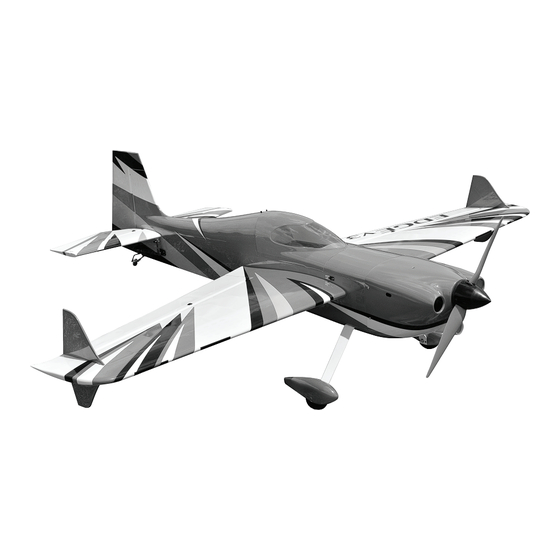
Glow and EP
ALL BALSA - PLY WOOD CONSTRUCTION.
COVERED WITH ORACOVER.
95% ALMOST READY TO FLY
SPECIFICATION
- Wingspan: 2,000 mm (78.74in).
- Length: 1,850 mm (72.83in).
- Weight: 5.6 - 5.8kg (12.34lbs).
- Wing area: 75.76 dm
- Wing loading: 73.91 g/dm
- Servo mount: 42mm x 21mm.
- Wing type: NacaAirfoil.
- Gear type: Aluminium Hi-grade for
main gear and tail gear (included).
- Spinner size: Plastic 85mm.
- Covering type: Genuine oracover
Instruction Manual Book
2
.
2
.
R
Item code: BH176
Parts listing required (not included):
- Radio: 06 channels minimum.
- Servo: 06 servos (HV High torque steel
gear servo).
- Engine:33 - 35 cc gas.
- Motor: Brushless outrunner
2500 - 3200W, 250KV.
- Propeller: Suit with your engine.
Recommended Motor and Battery set up
(not included):
- Motor: RIMFIRE.1.60.
- Lipo cell: 12 cells 4,000-5,500mAh.
- Receiver battery: 6-7.4V/ 2200-3000mAh.
- ESC: 80 - 100A.
Made in Vietnam.
Advertisement
Table of Contents

Related Manuals for Black Horse Model EDGE 540 V3


Summary of Contents for Black Horse Model EDGE 540 V3
- Page 1 Instruction Manual Book Item code: BH176 Glow and EP ALL BALSA - PLY WOOD CONSTRUCTION. COVERED WITH ORACOVER. 95% ALMOST READY TO FLY SPECIFICATION Parts listing required (not included): - Wingspan: 2,000 mm (78.74in). - Length: 1,850 mm (72.83in). - Radio: 06 channels minimum. - Weight: 5.6 - 5.8kg (12.34lbs).
-
Page 2: Table Of Contents
Thank you for purchasing Black Horse Model products. With over 18 years experience in production and fly testing, Black Horse Model is committed to bring the best quality products and good service to customers. Along with a team of creative engineers and skilled workers, we will always accompany with customers by our great experiences, fully enthusiasm... -
Page 3: Warranty
In that Black Horse Model has no control over the final assembly or material used for final assembly, SUGGESTION Black Horse Model is not responsible for loss of use , or other incidental or consequential damages. To avoid scratching your new airplane, do not... -
Page 4: Covering Tools
EDGE 540 V3 Item code: BH176 Instruction Manual FLIGHT WARNINGS ADHESIVES AND REQUIRED TOOLS When ready to fly, first extend the transmitter aerial. Thin CA Switch on the transmitter. 30-minute epoxy Switch on the receiver. 6-minute epoxy Check that the wings are correctly fitted to the Threadlocker thread locking cement fuselage. - Page 5 EDGE 540 V3 Item code: BH176 Instruction Manual • Officially designated AMA Air Show Teams (AST) are authorized to use devices and practices as defined within the Team AMA Program Document. (AMA Document #718.) (j) Not operate a turbine-powered aircraft, unless in compliance with the AMA turbine regulations. (AMA Document #510-A.)
-
Page 6: Parts Listing (Not Included)
EDGE 540 V3 Item code: BH176 Instruction Manual PARTS LISTING (NOT INCLUDED). Servo extension leads. 620mm ..2 pcs. Engine: 33 - 35 cc gas 220mm ..4 pcs. Propeller. Suit with your engine. LiPo. 6S - 22.2V- 4000-5000mAh. 2 Packs MOTOR Size: 1.60 .. - Page 7 EDGE 540 V3 Item code: BH176 Instruction Manual : Fuselage. Wing panel ( 2a, 2b Horizontal stabilizer (3a, 3b). : Rudder. Aluminium wing dihedral brace. : Top hatch fuselage (6a: Canopy, 6b: Wood frame hatch). : Fuel tank (7a: Clunk, 7b: Sttopper (three line)).
-
Page 8: Suggestion For Engine And Servo
EDGE 540 V3 Item code: BH176 Instruction Manual SUGGESTION FOR ENGINE AND SERVO PREPARATIONS Use a covering iron with a covering sock on • ENGINE: DLE 35 RA; OS 33GT high heat to tighten the covering if necessary. • SERVO: Two Options... -
Page 9: Installing The Ailerons Servos
EDGE 540 V3 Item code: BH176 Instruction Manual Make certain the hinges are adequately secured with glue. If they come loose in flight accidents may result. Apply epoxy glue INSTALLING THE AILERONS SERVOR 1. Install the rubber grommets and brass eyelets onto 4. - Page 10 EDGE 540 V3 Item code: BH176 Instruction Manual < Aileron servo > Servo ARM Hitec 24T.2’’ < Bottom view > 1.5mm Warning! Set all scerws securely. If they come off during flight you will lose control of your aircraft! Must be purchased <...
-
Page 11: Installing The Aileron Linkages
EDGE 540 V3 Item code: BH176 Instruction Manual INSTALLING THE AILERON LINKAGES 4. Center the aileron and hold it in place using a couple of pieces of masking tape. Adjust the 1. Install the control horn into the aileron. linkage until the aileron and the servo arm are both centered and then tighten the nut against. - Page 12 EDGE 540 V3 Item code: BH176 Instruction Manual < Bottom view > Assemble left and right sides the same way Apply threadlocker (screw cement).
- Page 13 EDGE 540 V3 Item code: BH176 Instruction Manual 4x12mm Plastic Screw - - - - - - 2 4x12mm < Bottom view >...
-
Page 14: Installing The Main Landing Gear
EDGE 540 V3 Item code: BH176 Instruction Manual INSTALLING THE MAIN LANDING 4 x 15mm Cap Screw 5 x 50mm Socket Head Cap Screw - - - - 2 5 mm Hex Nut 4mm Flat Washer 5mm Collar 4mm Spring Washer... - Page 15 EDGE 540 V3 Item code: BH176 Instruction Manual 5x50mm Socket Head Cap Screw 5mm Flat Washer 5mm Flat Washer 5mm Hex Nut 5mm Flat Washer 5mm Hex Nut 5mm Collar 85mm Wheel Main gear Wheel Pant 5mm Flat Washer Main gear...
- Page 16 EDGE 540 V3 Item code: BH176 Instruction Manual 3 x 10mm 85mm Wheel Button Screw Main gear Apply threadlocker (screw cement). Assemble left and right Wheel Pant sides the same way < Bottom view >...
- Page 17 EDGE 540 V3 Item code: BH176 Instruction Manual 4 x 15mm < Bottom view > < Bottom view > 4 x 15mm...
-
Page 18: Secure The Wing To The Fuselage
EDGE 540 V3 Item code: BH176 Instruction Manual SECURE THE WING TO THE FUSELAGE 6 x 25mm Plastic Screw Attach the wings to the fuselage and secure the wing panels. < Top view > 6 x 25mm... -
Page 19: Horizontal Stabilizer Installation
EDGE 540 V3 Item code: BH176 Instruction Manual HORIZONTAL STABILIZER INSTALLATION 1. Using a modeling knife, cut away the covering When you are sure that everything is aligned from the fuselage for the stabilizer and remove it. correctly, mix up a generous amount of 30 minute epoxy. - Page 20 EDGE 540 V3 Item code: BH176 Instruction Manual Top view 4 x 15mm Socket Head Cap Screw Bottom view...
-
Page 21: Rudder Installation
EDGE 540 V3 Item code: BH176 Instruction Manual RUDDER INSTALLATION Pinned Hinge < Top view > Pinned Hinge - - - - 4 90 Degree Cut off shaded portion Apply epoxy glue 9. Attach the clevis to the rudder servo. There should be... - Page 22 EDGE 540 V3 Item code: BH176 Instruction Manual < Bottom view > Aluminium ball 3x12mm Cable Cable rod 3x35mm 3x12mm 3.2mm Servo ARm Hitec 24T.4’’ Cut off shaded portion Must be purchased separately! Pay close attention here...
-
Page 23: Installing The Elevator Servo
EDGE 540 V3 Item code: BH176 Instruction Manual Rudder servo INSTALLING THE ELEVATOR SERVO INSTALLING THE ELEVATOR LINKAGES 1. Remove the covering from both size of the Repeat these step as installing the aileron linkages. fuselage. 2. Install two servo to the fuselage as shown. - Page 24 EDGE 540 V3 Item code: BH176 Instruction Manual < Bottom view > 3x12mm Elevator rod Servo ARm 3x12mm Must be purchased Hitec 24T.2’’ separately! Apply threadlocker Assemble left and right Pay close attention here (screw cement). sides the same way...
-
Page 25: Installing The Tail Wheel
EDGE 540 V3 Item code: BH176 Instruction Manual Assemble left and right sides the same way INSTALLING THE TAIL WHEEL 3 x 15mm Cap Screw #2-Tail wheel set < Bottom view > 3 x 15mm TP Screw 3 x 15mm... - Page 26 EDGE 540 V3 Item code: BH176 Instruction Manual 3 x 15mm < Bottom view >...
- Page 27 EDGE 540 V3 Item code: BH176 Instruction Manual < Bottom view > Spring < Bottom view >...
-
Page 28: Installing The Engine
EDGE 540 V3 Item code: BH176 Instruction Manual INSTALLING THE ENGINE May be you also need to trim some wood from the tri-angle Using plate of plywood (supplied with the kit) mark the holes wood for the installation is easy. - Page 29 EDGE 540 V3 Item code: BH176 Instruction Manual 5mm Flat Washer 16 x 5mm Flat Washer 5 x 90mm Socket Head Cap Screw - - - - - - - - - - - 4 5mm Spring Washer 16 x 5mm Rubber Washer...
- Page 30 EDGE 540 V3 Item code: BH176 Instruction Manual DLE 35 CC Electronic Ignition System Foam Zip tie DLE 35 CC Must be purchased separately!
-
Page 31: Installing The Stopper
EDGE 540 V3 Item code: BH176 Instruction Manual Throttle Lever Choke Lever INSTALLING THE STOPPER... -
Page 32: Installing The Fuel Tank
EDGE 540 V3 Item code: BH176 Instruction Manual Cut off shaded portion INSTALLING THE FUEL TANK 5. When satisfied with the alignment of the stopper assembly tighten the 3mm x 20mm machine screw until the rubber stopper expands and 1. Using a modeling knife, cut one length of silicon seals the tank opening. -
Page 33: Installing The Throttle
EDGE 540 V3 Item code: BH176 Instruction Manual Clunks #6 Fuel Tank Fuel Tank Silicone Tube Zip tie INSTALLING THE THROTTLE 1. Plug the throttle servo into the receiver and turn on Connector the radio system. Check to ensure that the throttle servo output shaft is moving in the correct direction. -
Page 34: Mounting The Cowl
EDGE 540 V3 Item code: BH176 Instruction Manual 1.5mm Throttle Servo Must be purchased Apply epoxy glue. separately! MOUNTING THE COWL 4. While holding the cowl firmly in position, drill 1. Remove the muffler and needle valve assembly four 1,6mm pilot holes through both the cowl from the engine. - Page 35 EDGE 540 V3 Item code: BH176 Instruction Manual 3 x 12mm TP Screw Cowl area cutout for engine head. Cut off shaded portion...
- Page 36 EDGE 540 V3 Item code: BH176 Instruction Manual 2.5 mm Apply instant glue Drill holes using the stated. (C.A glue, super glue). (in this case 1.5mm 1.5mm C . A...
-
Page 37: Installing The Spinner
EDGE 540 V3 Item code: BH176 Instruction Manual INSTALLING THE SPINNER Install the spinner back-plate, propeller and spinner cone. The propeller should not touch any part of the spinner cone. If it dose, use a sharp modeling knife and carefully trim away the spinner cone where the propeller comes in contact with it. - Page 38 EDGE 540 V3 Item code: BH176 Instruction Manual...
-
Page 39: Installing The Receiver And Battery
EDGE 540 V3 Item code: BH176 Instruction Manual INSTALLING THE SWITCH INSTALLING THE RECEIVER AND BATTERY 1. Plug the servo leads and the switch lead into the 1. The switch should be mounted on the fuselage receiver. You may want to plug an aileron... - Page 40 EDGE 540 V3 Item code: BH176 Instruction Manual 10 x 40mm 4 mm Spring Washer 4mm Washer 4x60mm Socket Head Cap Screw M5 Blind Nut 16 x 5mm Rubber Washer 16 x 5mm Flat Washer 5 mm Spring Washer 12 x 60mm...
- Page 41 EDGE 540 V3 Item code: BH176 Instruction Manual Battery Cord When rotating clock wise, change the connection of 2 wires. Must be purchased separately!
-
Page 42: Installing Canopy Fuselage
EDGE 540 V3 Item code: BH176 Instruction Manual INSTALLING CANOPY FUSELAGE Position the canopy so the rear frame on the canopy is aligned with the rear edge of the cockpit opening. Use canopy glue to secure the canopy to the canopy hatch. Use low-tack tape to hold the canopy in position until the glue fully cures. -
Page 43: Balancing
EDGE 540 V3 Item code: BH176 Instruction Manual Adhesive tape. LATERAL BALANCE BALANCING 1. It is critical that your airplane be balanced correctly. After you have balanced a plane on the C.G. Improper balance will cause your plane to lose You should laterally balance it. - Page 44 EDGE 540 V3 Item code: BH176 Instruction Manual 6 x 25mm Plastic Screw Plate of plywood 160-165 mm (6.3-6.5 in) Plate of plywood Pay close attention here Cut off excess. Apply instant glue Assemble left and right (CA glue, super glue).
-
Page 45: Control Throws
EDGE 540 V3 Item code: BH176 Instruction Manual In order to obtain the CG specified, reposition the receiver and other equipment. If not obtain the CG specified, add a weight and Do not fly before confirming the adjust. correct location of the CG. If the... -
Page 46: Decoration
EDGE 540 V3 Item code: BH176 Instruction Manual DECORATION 12mm 12mm Aileron Control < Side view > Left 11mm 11mm Elevator Control < Side view > Left 35mm 35mm Rudder Control FOR YOUR RADIO INSTALLATION BASIC CONNECTION FOR AIRPLANE AND ADJUSTMENT OF SERVOS Example of connection For more information, refer to radio system instruction manual. -
Page 47: Main Gear Dimensional Detail
EDGE 540 V3 Item code: BH176 Instruction Manual MAIN GEAR DIMENSIONAL DETAIL 17.0 34.0 183.0 13.0 34.0 17.0 TAIL GEAR DIMENSIONAL DETAIL 25.0 25.0... -
Page 48: Decoration
EDGE 540 V3 Item code: BH176 Instruction Manual DECORATION <Top view> <Bottom view> <Side view> Left <Side view> Right ORACCOVER #21-071 -Black #21-023 - Ferri Red #21-011 - Grey #21-010 - White... - Page 50 I/C FLYING WARNINGS Always operate in open areas, away from fly near power lines,aerials or AL WAYS adjust the engine from behind NEVER factories, hospitals, schools, buildings other dangerous areas including airports, the propeller, and do not allow any part of and houses etc.
- Page 51 I/C FLYING GUIDELINES Operate the control sticks on the ALWAYS land the model INTO When ready to fly, first extend transmitter and check that the the wind, this ensures that the the transmitter aerial. control surfaces move freely and in model lands at the slowest possible the CORRECT directions.
Need help?
Do you have a question about the EDGE 540 V3 and is the answer not in the manual?
Questions and answers