Table of Contents
Advertisement
Quick Links
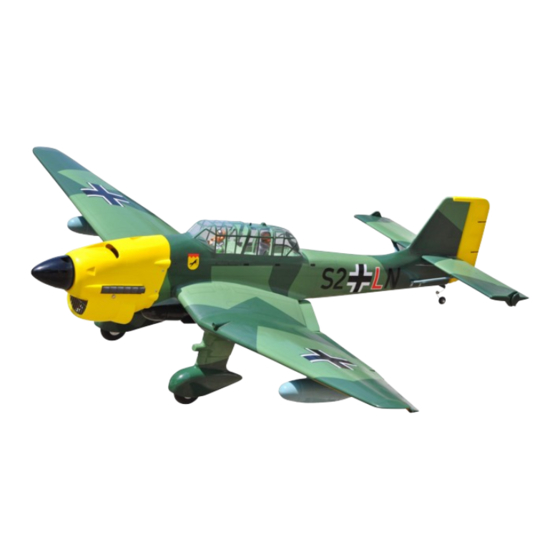
JU87-STUKA
BALSA AND PLY WOOD CONSTRUCTION.
COVERED WITH PVC PRINTING.
95% ALMOST READY TO FLY
SPECIFICATION
- Wingspan: 1,920mm (75.59in).
- Length: 1,560mm (61.42in.)
- Weight: 5.1kg (11.22lbs).
- Wing area: 62.4dm
- Wing loading: 81.7g/dm
- Wing type: Naca Airfoil.
- Gear type: Oleo struts (included).
- Spinner: 95mm.
- Servo mount: 42mm x 21mm.
Instruction Manual Book
.
2
.
2
Item code: BH80A.
New improvement.
Parts listing required (not included):
- Radio: 06 channels.
- Servo: 09 servos.
- Engine: 120 4 strokes; 120 2 strokes.
- Motor: Brushless outrunner 1800-2300W, 450KV.
- Propeller: Suit with your engine.
Recommended motor
and battery set up (not included):
- Motor: RIMFIRE.120.
- Lipo cell: 6 cells 4,000-5,000mAh.
- Receiver battery: 6V/ 1200-2000mAh NiMH.
- ESC: 80A.
Made in Vietnam.
Advertisement
Table of Contents

Related Manuals for Black Horse Model JU87-STUKA


Summary of Contents for Black Horse Model JU87-STUKA
- Page 1 Instruction Manual Book Item code: BH80A. JU87-STUKA New improvement. BALSA AND PLY WOOD CONSTRUCTION. COVERED WITH PVC PRINTING. 95% ALMOST READY TO FLY SPECIFICATION Parts listing required (not included): - Wingspan: 1,920mm (75.59in). - Radio: 06 channels. - Length: 1,560mm (61.42in.) - Servo: 09 servos.
-
Page 2: Tools And Supplies Needed
Instruction Manual This instruction manual is designed to help you build a great flying aeroplane. Please read this manual thoroughly before starting assembly of your JU87-STUKA. Use the parts listing below to identify all parts. WARNING Please be aware that this aeroplane is not a toy and if assembled or used incorrectly it is capable of causing injury to people or property. -
Page 3: Safety Precaution
JU87 - STUKA. Item code: BH80A. Instruction Manual Caution: This model is not a toy! This model is highly pre-fabricated and can be built in If you are a beginner to this type of powered model, a very short time. However, the work which you have to please ask an experienced model flyer for help and carry out is important and must be done carefully. -
Page 4: Installing The Aileron Servos
JU87 - STUKA. Item code: BH80A. Instruction Manual REPLACEMENT SMALL PARTS 3x12mm 4x15 mm 3x15mm 5x15mm 2x10mm 4x70mm 3x12mm 3 x 12mm 1. Oleo Strut 2. Wheels. 3. Plastic fairing for landing gear. 4. Wheel pants. 5. Plastic top wing. 6. -
Page 5: Installing The Aileron Linkages
JU87 - STUKA. Item code: BH80A. Instruction Manual 3) Place the servo into the servo tray. Center 2. INSTALLING THE AILERON CONTROL HORN the servo within the tray and drill 1.5mm pilot holes through the block of wood for each of the four mount- ... - Page 6 JU87 - STUKA. Item code: BH80A. Instruction Manual Flaslink Control horn Pushrod wire Bottom side. Secure the gear to the wing. Repeat the procedure to install the second aileron 4x15 mm linkages in the opposite wing half. After both linkages are completed. connect both of the aileron servo loads using a Y-harness you have purchased.
- Page 7 JU87 - STUKA. Item code: BH80A. Instruction Manual Install and secure the wheel. Secure Trim the covering. Secure the wheel pants. A+B Epoxy glue Drill a hole 2.5mm and secure 3x12mm Repeat the procedure to install the gear in the op- in the op- in the op- posite wing half.
-
Page 8: Installing The Engine Mount
JU87 - STUKA. Item code: BH80A. Instruction Manual PLASTIC TOP WING Top side. C/A glue. Repeat the procedure for the opposite wing half. IV. INSTALLING THE ENGINE MOUNT See pictures below: OPTION 2: ENGINE MOUNT 4x30mm There are two options: 1. -
Page 9: Installing The Fuselage Servos
JU87 - STUKA. Item code: BH80A. Instruction Manual 5) Test fit the stopper assembly into the tank. It may 145mm be necessary to remove some of the flashing around the tank opening using a modeling knife. If flashing is present, make sure none of it falls into the tank. -
Page 10: Installing The Throttle Pushrod
JU87 - STUKA. Item code: BH80A. Instruction Manual VI. COWLING Rudder servo Throttle servo Cowl area cutout for engine head. Elevator servo 3. INSTALLING THE THROTTLE PUSHROD 1) Slide the fiberglass cowl over the engine and line up the back edge of the cowl with the marks you made on the fuselage. -
Page 11: Installing Horizontal Stabilizer
JU87 - STUKA. Item code: BH80A. Instruction Manual VII. INSTALLING HORIZONTAL STABILIZER 1) Test fit the elevator to the horizontal stabilizer C/A glue. with the hinges. If the hinges don’t remain centered, stick a pin through the middle of the hinge to hold it in position. -
Page 12: Elevator Control Horn Installation
JU87 - STUKA. Item code: BH80A. Instruction Manual 5) With the horizontal stabilizer correctly aligned, mark the shape of the fuselage on the top and the bottom of the tail plane using a water soluble / non permanent felt-tip pen. Drill a hole 1.5 mm Elevator control horn... - Page 13 JU87 - STUKA. Item code: BH80A. Instruction Manual 2. ELEVATOR PUSHROD INSTALLATION Bottom side. Push in Elevator pushrod Silicone Tube M2 Lock nut 1) Using pliers, carefully make a 90 degree bend down at the mark made. Cut off the excess wire, leaving about 6mm beyond the blend.
-
Page 14: Mounting The Tail Wheel Bracket
JU87 - STUKA. Item code: BH80A. Instruction Manual Rudder servo Drill a hole 2.5mm diameter Snap keeper Rudder pushrod Flaslink Servo arm Pushrod wire XI. MOUNTING THE TAIL WHEEL 3) Secure the tail wheel bracket in place using BRACKET three 3mm x 12mm wood screws. -
Page 15: Installing The Switch, Receiver And Battery
JU87 - STUKA. Item code: BH80A. Instruction Manual 3x15mm Secure 3x12mm X. INSTALLING THE SWITCH, RECEIVER AND BATTERY INSTALLING PLASTIC BOMB FUSELAGE Please see pictures below. 1) Cut out the switch hole using a modeling knife. Use a 2mm drill bit and drill out the two mounting holes through the fuselage side. -
Page 16: Wing Attachment
JU87 - STUKA. Item code: BH80A. Instruction Manual XII. INSTALLING COCKPIT XI. WING ATTACHMENT FUSELAGE, PROPELLERS Locate the aluminium wing dihedral brace. Aluminium tube. 19mm. 655mm *** Test fit the aluminium tube dihedral brace into each wing haft. The brace should slide in easily. If not, use 220 grit sand around the edges and ends of the brace until it fits properly. -
Page 17: Installing The Spinner
JU87 - STUKA. Item code: BH80A. Instruction Manual Position the canopy so the rear frame on the canopy is BALANCING aligned with the rear edge of the cockpit opening. Use canopy glue to secure the canopy to the canopy hatch. ... -
Page 18: Control Throws
Rudder : 12mm right 12mm left 6) Properly balance the propeller. We wish you many safe and enjoyable flights 12mm JU87-STUKA with your 12mm Aileron control 15mm Flap control 10mm 10mm... - Page 19 I/C FLINGT WARNINGS Always operate in open areas, away ALWAYS adjust the engine from from factories, hospitals, schools, NEVER fly near power lines, behind the propeller, and do not buildings and houses etc. NEVER aerials or other dangerous areas allow any part of your body to be in fly your aircraft close to people or including airports, motorways etc.
Need help?
Do you have a question about the JU87-STUKA and is the answer not in the manual?
Questions and answers