Omron CJ1W-CORT21 Operation Manual
Cj-series.
user defined can unit
nj-series cpu unit
Hide thumbs
Also See for CJ1W-CORT21:
- Operation manual (290 pages) ,
- Operation manual (172 pages) ,
- Operation manual (317 pages)

Related Manuals for Omron CJ1W-CORT21


Summary of Contents for Omron CJ1W-CORT21
- Page 1 Machine Automation Controller CJ-series User Defined CAN Unit Operation Manual for NJ-series CPU Unit CJ1W-CORT21 User Defined CAN Unit W517-E2-01...
-
Page 3: Introduction
Thank you for purchasing a CJ-series CJ1W-CORT21 User Defined CAN Unit. This manual contains information that is necessary to use the CJ-series CJ1W-CORT21 User Defined CAN Unit for an NJ-series CPU Unit. Please read this manual and make sure you understand the func- tionality and performance of the NJ-series CPU Unit before you attempt to use it in a control system. -
Page 4: Relevant Manuals
Introduction Relevant Manuals There are three manuals that provide basic information on the NJ-series CPU Units: the NJ-series CPU Unit Hardware User’s Manual, the NJ-series CPU Unit Software User’s Manual, and the NJ-series Instructions Reference Manual. Most operations are performed from the Sysmac Studio Automation Software. Refer to the Sysmac Stu- dio Version 1 Operation Manual (Cat. -
Page 5: Manual Configuration
Introduction Manual Configuration NJ-series CPU Unit Hardware User’s Manual (Cat. No. W500) Section Description Section 1 This section provides an introduction to the NJ-series Controllers and their features, Introduction and gives the NJ-series Controller specifications. Section 2 This section describes the system configuration used for NJ-series Controllers. System Configuration Section 3 This section describes the parts and functions of the configuration devices in the NJ-... - Page 6 Introduction Sysmac Studio Version 1 Operation Manual (Cat. No. W504) Section Description Section 1 This section provides an overview and lists the specifications of the Sysmac Studio Introduction and describes its features and components. Section 2 This section describes how to install and uninstall the Sysmac Studio. Installation and Uninstallation Section 3 This section describes the basic concepts for designing an NJ-series System with the...
-
Page 7: Manual Structure
Introduction Manual Structure Page Structure The following page structure is used in this manual. Level 1 heading 4 Installation and Wiring Level 2 heading Mounting Units Level 3 heading Level 2 heading Gives the current headings. Level 3 heading 4-3-1 Connecting Controller Components The Units that make up an NJ-series Controller can be connected simply by pressing the Units together and locking the sliders by moving them toward the back of the Units. -
Page 8: Sections In This Manual
Introduction Sections in this Manual Features and System Configuration Nomenclature and Installation Data Exchange with the CPU Unit Message Communications Communications Timing Troubleshooting and Maintenance Appendices Index CJ-series User Defined CAN Unit Operation Manual for NJ-series CPU Unit (W517) -
Page 9: Table Of Contents
CONTENTS Introduction....................... 1 Relevant Manuals ..................... 2 Manual Configuration....................3 Manual Structure ...................... 5 Sections in this Manual.................... 6 CONTENTS ........................ 7 Read and Understand this Manual ................ 10 Safety Precautions ....................13 Precautions for Safe Use ..................18 Precautions for Correct Use .................. 24 Regulations and Standards ................... - Page 10 Section 2 Nomenclature and Installation Nomenclature and Installation ....................2-2 2-1-1 Nomenclature and Functions ..................... 2-2 2-1-2 Switch Settings ........................... 2-5 Installing the User Defined CAN Unit ..................2-8 2-2-1 System Configuration Precautions ..................... 2-8 2-2-2 Mounting ............................ 2-8 2-2-3 Handing Precautions ........................
- Page 11 Section 6 Troubleshooting and Maintenance Overview ..........................6-2 6-1-1 Troubleshooting the User Defined CAN Unit ................6-2 Troubleshooting with the User Defined CAN Unit Indicators ..........6-4 6-2-1 Run LED Indicator ........................6-4 6-2-2 ERR LED Indicator ........................6-5 6-2-3 Two 7-segment Display ......................
-
Page 12: Read And Understand This Manual
WHETHER SUCH CLAIM IS BASED ON CONTRACT, WARRANTY, NEGLIGENCE, OR STRICT LIABILITY. In no event shall the responsibility of OMRON for any act exceed the individual price of the product on which liability is asserted. IN NO EVENT SHALL OMRON BE RESPONSIBLE FOR WARRANTY, REPAIR, OR OTHER CLAIMS... - Page 13 Application Considerations SUITABILITY FOR USE OMRON shall not be responsible for conformity with any standards, codes, or regulations that apply to the combination of products in the customer's application or use of the products. At the customer's request, OMRON will provide applicable third party certification documents identifying ratings and limitations of use that apply to the products.
- Page 14 Performance data given in this manual is provided as a guide for the user in determining suitability and does not constitute a warranty. It may represent the result of OMRON's test conditions, and the users must correlate it to actual application requirements. Actual performance is subject to the OMRON Warranty and Limitations of Liability.
-
Page 15: Safety Precautions
Safety Precautions Definition of Precautionary Information The following notation is used in this manual to provide precautions required to ensure safe usage of an NJ-series Controller. The safety precautions that are provided are extremely important to safety. Always read and heed the information provided in all safety precautions. The following notation is used. - Page 16 Symbols The circle and slash symbol indicates operations that you must not do. The specific operation is shown in the circle and explained in text. This example indicates prohibiting disassembly. The triangle symbol indicates precautions (including warnings). The specific operation is shown in the triangle and explained in text. This example indicates a precaution for electric shock.
- Page 17 WARNING During Power Supply Do not touch any of the terminals or terminal blocks while the power is being supplied. Doing so may result in electric shock. Do not attempt to take any Unit apart. In particular, high-voltage parts are present in the Power Supply Unit while power is supplied or immediately after power is turned OFF.
- Page 18 WARNING Fail-safe Measures Unintended outputs may occur when an error occurs in variable memory or in memory used for CJ-series Units. As a countermeasure for such prob- lems, external safety measures must be provided to ensure safe operation of the system. Provide measures in the communications system and user program to ensure safety in the overall system even if errors or malfunctions occur in data link communications or remote I/O communications.
- Page 19 Caution Application Do not touch any Unit when power is being supplied or immediately after the power supply is turned OFF. Doing so may result in burn injury. Wiring Be sure that all terminal screws and cable connector screws are tightened to the torque specified in the relevant manuals.
-
Page 20: Precautions For Safe Use
Precautions for Safe Use Disassembly and Dropping • Do not attempt to disassemble, repair, or modify any Units. Doing so may result in malfunction or fire. • Do not drop any Unit or subject it to abnormal vibration or shock. Doing so may result in Unit malfunc- tion or burning. - Page 21 • Do not apply voltages or connect loads to the Output Units or slaves in excess of the maximum rat- ings. • Surge current occurs when the power supply is turned ON. When selecting fuses or breakers for external circuits, consider the above precaution and allow sufficient margin in shut-off performance. Refer to the relevant manuals for surge current specifications.
- Page 22 The Power Supply Unit may continue to supply power to the rest of the Controller for a few seconds after the power supply turns OFF. The PWR indicator is lit during this time. Confirm that the PWR indicator is not lit before you perform any of the above. Operation •...
- Page 23 • You cannot upload or download information for forced refreshing with the Sysmac Studio. After downloading data that contains forced refreshing, change to RUN mode and then use the Sysmac Studio to perform the operation for forced refreshing. Depending on the difference in the forced status, the control system may operate unexpectedly. •...
- Page 24 • EtherCAT communications are not always established immediately after the power supply is turned ON. Use the system-defined variables in the user program to confirm that communications are estab- lished before attempting control operations. • If frames sent to EtherCAT slaves are lost due to noise or other causes, slave I/O data is not commu- nicated, and the intended operation is sometimes not achieved.
- Page 25 Unit Replacement • We recommend replacing the Battery with the power turned OFF to prevent the CPU Unit’s sensitive internal components from being damaged by static electricity and to prevent malfunctions. The Bat- tery can be replaced without turning OFF the power supply. To do so, always touch a grounded piece of metal to discharge static electricity from your body before you start the procedure.
-
Page 26: Precautions For Correct Use
Precautions for Correct Use Storage, Mounting, and Wiring • Do not operate or store the Controller in the following locations. Operation may stop or malfunctions may occur. • Locations subject to direct sunlight • Locations subject to temperatures or humidity outside the range specified in the specifications •... - Page 27 Error Processing • In applications that use the results of instructions that read the error status, consider the affect on the system when errors are detected and program error processing accordingly. For example, even the detection of a minor error, such as Battery replacement during operation, can affect the system depending on how the user program is written.
- Page 28 SD Memory Cards • Insert the SD Memory Card all the way. • Do not turn OFF the power supply to the Controller during SD Memory Card access. The files may be corrupted. If there is a corrupted file in the SD Memory Card, the file is automatically deleted by the restoration function when the power supply is turned ON.
-
Page 29: Regulations And Standards
Concepts EMC Directive OMRON devices that comply with EC Directives also conform to the related EMC standards so that they can be more easily built into other devices or the overall machine. The actual products have been checked for conformity to EMC standards.* Whether the products conform to the standards in the system used by the customer, however, must be checked by the customer. - Page 30 Keep communication cables as short as possible and ground to 100 Ω min. Trademarks • Sysmac and SYSMAC are trademarks or registered trademarks of OMRON Corporation in Japan and other countries for OMRON factory automation products. • Windows, Windows 98, Windows XP, Windows Vista, and Windows 7 are registered trademarks of Microsoft Corporation in the USA and other countries.
-
Page 31: Unit Versions
□ DDMYY: Lot number, : For use by OMRON, xxxx: Serial number “M” gives the month (1 to 9: January to September, X: October, Y: November, Z: December) MAC address Gives the MAC address of the built-in port on the Unit. - Page 32 Right-click any open space in the Unit Editor and select Production Information. The Production Information Dialog Box is displayed. Simple Display Detailed Display In this example, “Ver.1.0” is displayed next to the unit model. The following items are displayed. CPU Unit CJ-series Units Unit model Unit model...
-
Page 33: Related Manuals
Sysmac Studio. tions of the Sysmac Studio. CJ-series User Defined W517 CJ1W-CORT21 Learning about the func- The functions and operating procedures when CAN Units Operation tions and operating proce- the CJ-series User Defined CAN Unit is used in... -
Page 34: Revision History
Revision History A manual revision code appears as a suffix to the catalog number on the front and back covers of the manual. W517-E1-01 Cat. No. Revision code Revision code Date Revised content April 2012 Original production CJ-series User Defined CAN Unit Operation Manual for NJ-series CPU Unit (W517) -
Page 35: Features And System Configuration
Features and System Configuration This section provides an introductory overview of CAN bus, its functions and how to setup and configure a network. It also addresses the User Defined CAN Unit its config- uration, features and specifications. 1-1 User Defined CAN Unit Features ....... . . 1-2 1-2 Overview of CAN Bus . -
Page 36: User Defined Can Unit Features
1 Features and System Configuration User Defined CAN Unit Features The User Defined CAN Unit (CJ1W-CORT21) is a CPU Bus Unit which can be installed on an NJ-series Controller. The User Defined CAN Unit will interface between the CPU of the NJ-series controller and the CAN bus. - Page 37 1 Features and System Configuration Sending CAN Messages Message commands are used to define the CAN messages for the User Defined CAN Unit. These commands define which messages can be send by the Unit, the mode of sending, and the timing for when messages are sent.
- Page 38 1 Features and System Configuration Condition Unit Processing The integrity check for the message fails. The The User Defined CAN Unit sends an error frame on the CAN check is done by the CAN Unit directly, or the bus. firmware. The message is rejected by the CAN controller and/or the firmware, no notification is sent to the application layer.
-
Page 39: Overview Of Can Bus
1 Features and System Configuration Overview of CAN Bus The Controller Area Network (CAN) is a serial communications protocol which efficiently supports dis- tributed real-time control with a very high level of security. Its domain of application ranges from high speed networks to low cost multiplex wiring. -
Page 40: Can Communication Protocol
1 Features and System Configuration 1-2-1 CAN Communication Protocol In general, the CAN communication protocol is based on the Open System Interconnection (OSI) refer- ence model in accordance with the international standard ISO-7498 (see the following illustration). OSI Reference Model ISO-7498 The model defines 7 layers of communication functions, two of which (layers 1 and 2) are used in CAN. - Page 41 1 Features and System Configuration Serial Bus A number of different data rates are defined from 1Mbps to 10kbps. Cable length depends on the data rate used. The maximum line length is 5 km and the minimum is 25 meters at 1Mbps. Termina- tion resistors are used at each end of the cable.
- Page 42 1 Features and System Configuration expected to occur; the distance between an edge that occurs outside of Sync_Seg and the Sync_Seg is called the phase error of that edge. A signal-edge is expected to lie in this segment, and is used to synchronize the bus input to the system clock. The Propagation Time Segment Prop_Seg is intended to compensate for the physical delay times within the CAN network.
- Page 43 1 Features and System Configuration Data Frame The data frame is composed of an Arbitration field, Control field, Data field, CRC field, and an ACK field. The frame begins with a 'Start of frame' [SOF], and ends with an 'End of frame' [EOF] space. The data field may be from 0 to 8 bytes.
-
Page 44: Physical Can Connection
1 Features and System Configuration Identifier Length Standard format The identifier’s length is 11 bits and corresponds to the Base Id in the Extended format. The indenti- fier is interpreted as an integer value in the hexadecimal range 0x0000 - 0x07FF. Extended format In contrast to the Standard format, the identifier in this format consists of 29 bits. -
Page 45: Principles Of Data Exchange
1 Features and System Configuration 1-2-3 Principles of Data Exchange Unit Addressing When data is transmitted by CAN, no units are addressed, but instead, the content of the message (e.g. rpm or engine temperature) is designated by an identifier that is unique throughout the net- work. -
Page 46: Efficiency Of Bus Allocation
1 Features and System Configuration The priority at which a message is transmitted compared with another less urgent message is spec- ified by the identifier of the message concerned. The priorities are defined during system design in the form of corresponding binary values and cannot be changed dynamically. The identifier with the lowest binary number has the highest priority. - Page 47 1 Features and System Configuration Non-destructive Bus Access With methods of this type the bus is allocated to one and only one unit either immediately or within a specified time following a single bus access (by one or more units). This ensures that each bus access by one or more units leads to an unambiguous bus allocation.
-
Page 48: Message Frame Formats
1 Features and System Configuration These requests are handled in the order of the importance of the messages for the system as a whole. This proves especially advantageous in overload situations. Since bus access is prioritized on the basis of the messages, it is possible to guarantee low individual latency times in real-time systems. -
Page 49: Detecting And Signaling Errors
1 Features and System Configuration CRC Field The CRC field contains the CRC sequence, followed by a delimiter. this CTC-delimiter is a single recessive bit. The frame check sequence is derived from a cyclic redundancy code best suited for frames with bit counts less then 127 bits (BCH code). - Page 50 1 Features and System Configuration Bit Stuffing The coding of the individual bits is tested at bit level. The bit representation used by CAN is NRZ (non-return-to-zero) coding, which guarantees maximum efficiency in bit coding. The synchroniza- tion edges are generated by means of bit stuffing, i.e. after five consecutive equal bits the sender inserts into the bit stream a stuff bit with the complementary value, which is removed by the receiv- ers.
-
Page 51: Data Reliability Of The Can Protocol
1 Features and System Configuration Error Reset In bus off mode, the CAN unit has its communication disabled. The user program in the CPU can enable the communication using a message command. Enabling the communication will reset both the receive and transmit counter. 1-2-8 Data Reliability of the CAN Protocol ... -
Page 52: Extended Format Can Message
1 Features and System Configuration 1-2-9 Extended Format CAN Message 29-bit Identifier The Society of Automotive Engineers (SAE) "Truck and Bus" sub-committee standardized signals and messages as well as data transmission protocols for various data rates. It became apparent that standardization of this kind is easier to implement when a longer identification field is available. -
Page 53: 1-2-10 Implementations Of The Can Protocol
1 Features and System Configuration 1-2-10 Implementations of the CAN Protocol Overview Communication is identical for all implementations of the CAN protocol. There are differences, how- ever, with regard to the extent to which the implementation takes over message transmission from the micro controllers which follow it in the circuit. -
Page 54: Specifications
General specifications of the CJ-series User Defined CAN Unit conform to those of the NJ-series CPU Units. Functional and Performance Specifications Item Specification User Defined CAN Unit model CJ1W-CORT21 Applicable Controller NJ Series Unit classification CPU Bus Unit Applicable unit numbers... - Page 55 *1 FINS message communications are available with the NJ Series. However, with these functions, not all areas of the NJ-series CPU Unit are accessible. If these functions need to be used, such as to connect to existing equipment, please consult with your OMRON representative. 1-21...
-
Page 56: Basic Operating Procedures
1 Features and System Configuration Basic Operating Procedures 1-4-1 Network Installation Procedure Determine a suitable baud rate for the system. Determine the node arrangement, the wiring configura- tion, and the cable lengths. A) Restrictions on lenghts of communication lines. B) Separation from noise sources. Do (1) and (2) above meet the Check CAN specifications? -
Page 57: User Defined Can Unit Startup Procedure
1 Features and System Configuration 1-4-2 User Defined CAN Unit Startup Procedure The basic operating procedures for the User Defined CAN Unit are described here. Use Sysmac Studio to create programs and to configure the Unit. For details on operations of Sysmac Studio, refer to the Sysmac Studio Version 1 Operation Manual (Cat. - Page 58 1 Features and System Configuration Allocation of User-defined Variables to the Memory Used for CJ- series Unit Bits and words are allocated to the memory used for CJ-series when you configure the User Defined CAN unit with message commands. • send buffers specification •...
-
Page 59: Nomenclature And Installation
Nomenclature and Installation This section describes the nomenclature and installation of the User Defined CAN Unit. 2-1 Nomenclature and Installation ........2-2 2-1-1 Nomenclature and Functions . -
Page 60: Nomenclature And Functions
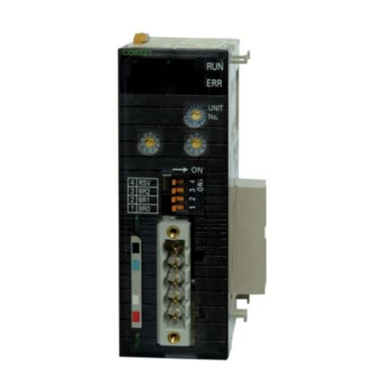
2 Nomenclature and Installation Nomenclature and Installation 2-1-1 Nomenclature and Functions CJ1W-CORT21 Indicators CORT21 Unit No. switch UNIT This switch sets the unit number of the User Defined CAN Unit as a one-digit hexadecimal value. These switches are reserved for future use. - Page 61 2 Nomenclature and Installation Indicator Color Status Condition Green Normal operating status. The Unit state is ST3, ST4 or ST5. • A non-recoverable fatal error has occurred • Unit state is ST2 and a start-up error has occurred. Power is not supplied or the Unit is in state ST1 or ST2.
- Page 62 2 Nomenclature and Installation Seven Segment Digits Status Display Unit not mounted in CPU Rack Not Lit Initializing (State ST1*) Start-up error (State ST2*) Unit not configured (State ST3*) Lit: FF CAN communications are disabled (State ST4*) CAN communications are enabled (State ST5*) Lit: 00 CAN network power failure Blink: 01...
-
Page 63: Switch Settings
2 Nomenclature and Installation Action Indicator State Areas configured, message command Green 2902 State = ST4* 7-Segment Left dot Right dot Buffer(s) configured, Green message command 2903 - 2906 State = ST4* 7-Segment Left dot Right dot *See section 2-2-5 Unit States for more information. 2-1-2 Switch Settings Unit No. - Page 64 2 Nomenclature and Installation Rotary Switches The two 10-position rotary switches below the Unit No. are reserved for future use. DIP Switch The DIP switches on the front of the User Defined CAN Unit are used to set the baud rate and implicitly, the sample point.
- Page 65 2 Nomenclature and Installation CAN Bus Connector The CAN bus connector is a 5-pin open style connector. This CAN connector is located on the front side of the Unit, and is a male connector with five pins. female male Color stickers that match communication cable colors are attached to the communications connectors. Match the colors when connecting communication cables to the connectors, the colors can be found in the next table.
-
Page 66: Installing The User Defined Can Unit
2 Nomenclature and Installation Installing the User Defined CAN Unit 2-2-1 System Configuration Precautions You can mount up to 16 Units on the CPU Rack or an Expansion Rack per CPU (but no more than 10 Units on one Rack). 2-2-2 Mounting Carefully align the connectors to mount the User Defined CAN Unit. -
Page 67: Handing Precautions
2 Nomenclature and Installation 2-2-3 Handing Precautions • Always turn OFF the Controller before you mount or dismount a Unit or connect or disconnect cables. • Provide separate conduits or ducts for the I/O lines to prevent noise from high-tension lines or power lines. -
Page 68: Unit States
2 Nomenclature and Installation 2-2-5 Unit States The User Defined CAN Unit has several states. These states are visualized in the figure below. Events will force the Unit to switch to a different state, these events can be user initialized or caused by system behaviour (or error conditions detected in the system). - Page 69 2 Nomenclature and Installation Cyclic refresh of message State Name Description command(s) Initializing The Unit executes start-up tests and ini- tializes the CPU bus communications. Start-up error A start-up error was detected during start- up tests or during the intialization of the CPU communication bus.
- Page 70 2 Nomenclature and Installation 2-12 CJ-series User Defined CAN Unit Operation Manual for NJ-series CPU Unit (W517)
-
Page 71: Data Exchange With The Cpu Unit
Data Exchange with the CPU Unit This section provides information on exchangin data between the User Defined CAN Unit and NJ-series CPU Units. 3-1 Data Exchange with the CPU Unit ....... . 3-2 3-1-1 Data Flow . -
Page 72: Data Flow
3 Data Exchange with the CPU Unit Data Exchange with the CPU Unit Data exchange between this Unit and the CPU Units uses the I/O port and memory for CJ-series Unit allocated to the User Defined CAN Unit. 3-1-1 Data Flow The CPU Units and CJ-series User Defined CAN Units exchange data as shown in the table and chart below. - Page 73 3 Data Exchange with the CPU Unit Loca- Item Description tion/Variable Control and *_EnblCANC Flags to control the Unit behavior and to show the status of the Unit. Status Flags omm, *_StaComm Send Triggers Configurable Triggers to send CAN messages on demand. Bits in the send trigger area will send a message if the bit-value has a rising edge and the bit is asso- ciated with an output buffer.
- Page 74 3 Data Exchange with the CPU Unit CPU Unit User Defined CAN Unit I/O port User program Communication Enable, Communication Enable, Status, No. of Delayed Status, No. of Delayed Messages Messages Communication Enable Device variable AT specification for CJ-series Unit Status, Number of Delayed Messages Memory used for...
-
Page 75: Accessing From The User Program
3 Data Exchange with the CPU Unit Device Variable for CJ-series Unit Device variables for CJ-series Units are variables for which AT is specified for the I/O port explained below. The user program uses device variables for CJ-series Unit to access the Configuration Unit such as the User Defined CAN Unit. - Page 76 3 Data Exchange with the CPU Unit From the user program, the following is used to exchange various types of information: Data type I/O port, memory used for CJ-series Unit Access method Communication Enable, Status, Number Operation Data Device variables of Delayed Messages for CJ-series Unit Memory Areas...
- Page 77 3 Data Exchange with the CPU Unit How to Create User-defined Variables Use the Sysmac Studio to register user-defined variables to the variable table. Use user-defined vari- ables to specify the AT specification of the memory used for CJ-series Unit to which buffer and trigger areas are allocated.
-
Page 78: Device Variable For Cj-Series Unit
3 Data Exchange with the CPU Unit Device Variable for CJ-series Unit When you operate and reference software switches and statuses, use the following device variables for CJ-series Unit allocated to the I/O port of this Unit. Name of device variable for Type Area CJ-series Unit... -
Page 79: Status Communication
3 Data Exchange with the CPU Unit 3-2-2 Status Communication Use one of the following device variables for CJ-series Unit to monitor Status. Communication from the user program: • WORD-type device variable for CJ-series Unit holding all switch functions contained in Status Com- munication •... - Page 80 3 Data Exchange with the CPU Unit The following device variables for CJ-series Unit are used to reference individual information. Name of device variables for Type Area Function CJ-series Unit *_EnblComm BOOL Enabled <Operation specifications> Communi- TRUE: cation CAN communications enabled and unit state is ST5 (communicating).
- Page 81 3 Data Exchange with the CPU Unit Name of device variables for Type Area Function CJ-series Unit *_NetPwrErr BOOL Network- <Operation specifications> Power Fail- TRUE: Error ER10 active indicating a power fail- ure while communicating. FALSE: Network power is within acceptable range. Default: FALSE *_BusoffErr BOOL...
-
Page 82: Number Of Delayed Messages
3 Data Exchange with the CPU Unit 3-2-3 Number of Delayed Messages When the *_SendOver variable is TRUE, *_DelayMsgNo will provide the number of delayed messages in BCD format. For details on the *_SendOver variable, see 3-2-2 Status Communication. Name of device variable for Type Area Function... -
Page 83: Message Communications
Message Communications This section describes message communications sent from the user program in the CPU Unit. 4-1 Overview ........... . . 4-2 4-1-1 Outline of Message Communications . -
Page 84: Overview
Message communications enable messages to be sent between nodes on a CAN network when required by system conditions. The messages can be sent between CPUs, between an OMRON CPU and a User Defined CAN unit, or between slaves. They can be used to send/receive data, read time data, error histories, and other data or control operation, e.g., refreshing with user-specified values. - Page 85 4 Message Communications Additional Information The User Defined CAN Unit supports sending and recieving functions for messages. Every mes- sage in CAN communication has an identifier. The configurable options for these message iden- tifiers are 29-bit or 11-bit size for each input and output message buffer. See sections below for more information.
-
Page 86: Unit Configuration And Control
4 Message Communications Unit Configuration and Control In order to operate a CAN network, each unit in the network needs to be configured with software (user program) configuration. The total process of network and unit configuration involves: • Setting up the physical network topology •... - Page 87 4 Message Communications Command Block Number of Command Memory Start Memory Start Number Memory Start Memory Start Receive Code Area Address Area Address of Send Area Address Area Address Messages Messages Receive Buffers Receive Trigger Send Buffers Send Trigger The following table defines the minimum and maximum values for each item in the command block. Setting Minimum Value (Hex) Maximum Value (Hex)
- Page 88 4 Message Communications Note 1 Using the maximum address send/receive buffers will result in an error because the buffers consume 5 words each. Therefore, use the following equation to determine the maximum allowable memory area for a start address buffer: •...
- Page 89 4 Message Communications 2 On response code 0000, the unit will set to zero: • The Receive Message buffers that are added to the configuration • The Receive Trigger bits that are added to the configuration (the Send Trigger bits are not cleared) ...
- Page 90 4 Message Communications If any of these bits is set, *_MsgRcv is ON. If all these bits are reset, *_MsgRcv is OFF. The location S of the receive trigger word is configured with the command code 2902. This memory area contains input words. The length of the area is determined by the number of configured receive message buffers.
- Page 91 4 Message Communications Big endian: Little endian: Word T Data length (number of bytes) Data length (number of bytes) Word T + 1 Data byte 0 Data byte 1 Data byte 1 Data byte 0 Word T + 2 Data byte 2 Data byte 3 Data byte 3 Data byte 2...
-
Page 92: Configure 11-Bit Id Output Message Buffer (2903)
4 Message Communications Big endian: Little endian: Word U Data length (number of bytes) Data length (number of bytes) Word U + 1 Data byte 0 Data byte 1 Data byte 1 Data byte 0 Word U + 2 Data byte 2 Data byte 3 Data byte 3 Data byte 2... - Page 93 4 Message Communications Setting Minimum Value (Hex) Maximum Value (Hex) Setting Details Buffer Number 0000 027F Defines which buffer to configure (0 to 639) Identifier 11-bit 0000 07FF Identifier value Method of Sending 0001 0004 • 0001: Message will be sent when the corre- sponding bit in the send trigger area changes...
-
Page 94: Configure 29-Bit Id Output Message Buffer (2904)
4 Message Communications End Code (hex) Description Condition Correction 1103 No area type Unit state = ST3 or ST4 and Number of output buffers the memory area is not avail- exceeds the number of out- able put buffers configured by message command 2902. - Page 95 4 Message Communications The following table defines the minimum and maximum values for each item in the command block with setting details. Setting Minimum Value (Hex) Maximum Value (Hex) Setting Details Buffer Number 0000 027F Defines which buffer to configure (0 to 639) Identifier 29-bit 00000000 1FFF FFFF...
-
Page 96: Configure 11-Bit Id Input Message Buffer (2905)
4 Message Communications End Code (hex) Description Condition Correction 1002 The command length is Too few parameters sent in insufficient for the smallest the command. command Correct the command and re- send. 1103 Address range destination Unit state = ST4 or ST5 and Number of output buffers error buffer number is greater than... - Page 97 4 Message Communications The following table defines the minimum and maximum values for each item in the command block with setting details. Setting Minimum Value (Hex) Maximum Value (Hex) Setting Details Buffer Number 0000 027F Defines which buffer to configure (0 to 639) Identifier 11-bit 0000 07FF...
-
Page 98: Configure 29-Bit Id Input Message Buffer (2906)
4 Message Communications Note 1 On response code 0000, the unit configures the input (receive) message buffer identified with buffer number with the following properties: • Extended identifier length (see additional information below) • Identifier number • Big or little endian format, see Send Buffer Area on page 8 Additional Information The last command 2905 or 2906 sent to the unit determines whether 11-bit or 29-bit identifiers are used for all input message buffers. -
Page 99: Direct Transmit Of An 11-Bit Id Can Message (2907)
4 Message Communications End Code (hex) Description Condition Correction No response Unit state = ST1 or ST2 Restart the CPU, make sure that the unit is mounted and wired correctly Normal completion Unit state = ST4 or ST5 and Command is executed and 0000 all parameters are in range operation is normal. - Page 100 4 Message Communications Command Block Command Identifier Data Big or Data, 8 Bytes Code 11-bit Length Little in Bytes Endian The following table defines the minimum and maximum values for each item in the command block with setting details. Setting Minimum Value (Hex) Maximum Value (Hex) Setting Details...
-
Page 101: Direct Transmit Of An 29-Bit Id Can Message (2908)
4 Message Communications End Code (hex) Description Condition Correction 110C Parameter error Unit state = ST5 and one or Correct the parameters, more parameters are not in range 2201 Not executable in current Unit state = ST3 or ST4 Nothing configured. Perform mode message command 2902 before executing this com-... - Page 102 4 Message Communications Response Block Issuing a Direct Transmit of an 29-bit ID CAN Message command will result in the following response End Codes. Command Code Code End Code (hex) Description Condition Correction No response Unit state = ST1 or ST2 Restart the CPU, make sure that the unit is mounted and wired correctly...
-
Page 103: Setting The Can Bit Rate And Sample Point (2909)
4 Message Communications 4-2-8 Setting the CAN Bit Rate and Sample Point (2909) The bit rate can be set in 2 ways: • The 8 bit rates recommended by CANopen can be selected with the DIP-switches on the front of the Unit. -
Page 104: Error Log Read (2102)
4 Message Communications End Code (hex) Description Condition Correction 1002 The command length is Too few parameters sent in the command. insufficient for the smallest Correct the command and re- command send. 110C Parameter error Unit state = ST3 or ST4 and Correct the parameters. -
Page 105: Error Log Clear (2103)
4 Message Communications Response Block Issuing an Error Log Read command will result in the following response End Codes. 10 bytes each Maximum Number Number Command End Code Error log records Number of stored of records code of stored records records End Code (hex) Description... - Page 106 4 Message Communications Response Block Issuing an Error Log Clear command will result in the following response End Codes. End code Command code End Code (hex) Description Condition Correction 0000 Normal Completion 250F Memory Writing Error. Error Log was not cleared normally 260B Cannot Clear Error Log...
-
Page 107: Communications Timing
Communications Timing This section describes the overall specifications and the communication performance of the User Defined CAN Unit. 5-1 Performance ..........5-2 5-1-1 I/O Refresh Time . -
Page 108: Performance
5 Communications Timing Performance The overall performance of the User Defined CAN Unit depends on the performance of the host CPU interface and the performance of the CAN interface. In the next two sub-sections, these factors will be described. 5-1-1 I/O Refresh Time The I/O refresh time of the User Defined CAN Unit depends on the size of the receive flags area, the size of the send trigger area, on the number of input buffers and on the number of output buffers that... - Page 109 5 Communications Timing Example 2 • Number of output buffers: 640 • Number of configured output buffers: 1 Every time the trigger configured message is ON, the evaluation time of all output buffers (being 640) will be: 10.0 + (4.3 * 639) = 2.76 (milliseconds). Precautions for Correct Use Precautions for Correct Use To optimize the evaluation time for the triggered send mode, set the number of output buffers...
-
Page 110: Input Message Processing Time
5 Communications Timing SM3, Cyclic Mode In Cyclic mode the evaluation time differs for output buffers that should be sent and for which the cyclic time has not yet elapsed. Output buffers with elapsed cyclic time have an evaluation time of 11.6 micro- seconds. -
Page 111: Can Interface
5 Communications Timing • Set the number of input buffers with message command 2902 to the same amount as the number of configured input buffers (that is the total number of buffers configured with message command 2905 or 2906). • Configure the order of input buffers according to the frequency of received messages, i.e. in descending order. - Page 112 5 Communications Timing Minimum I/O Response Time CORT21 Input node Output node minimum I/O response time : Input Node ON (OFF) delay : Unit Processing time for Received messages : Output Node ON (OFF) delay : Unit Processing time for Transmitted messages : Message Delay time : Program Execution time : I/O Refresh time...
- Page 113 5 Communications Timing Maximum I/O Response Time CORT21 Input node Output node maximum I/O response time : Input Node ON (OFF) delay : Unit Processing time for Received messages : Output Node ON (OFF) delay : Unit Processing time for Transmitted messages : Message Delay time : Program Execution time : I/O Refresh time...
-
Page 114: Transmission Of Can Messages
5 Communications Timing 5-1-6 Transmission of CAN Messages Transmitting With Direct Transmit Mode The following figure shows the sequence of direct transmitting a CAN message using message com- mand 2907 or 2908. 2907, 2908 CORT21 Output Node : The transmission time of a user defined CAN message : The I/O Refresh time : The Program Execution time After the content of the message command is transferred to the User Defined CAN Unit, the unit imme-... -
Page 115: Reception Of Can Messages
5 Communications Timing Transmitting With Send Mode Sending messages with SM1, SM2 or SM3 differs from direct sending CAN messages. There is no delay between the start of ‘program execution’ and passing the message to the User Defined CAN Unit. SM1, SM2, SM3 CORT21 Output node... - Page 116 5 Communications Timing 5-10 CJ-series User Defined CAN Unit Operation Manual for NJ-series CPU Unit (W517)
- Page 117 Troubleshooting and Maintenance This section describes error processing, periodic maintenance operations and trouble- shooting procedures needed to keep the User Defined CAN Unit operating properly. It is recommended to read through the error processing procedures before operation so that operating errors can be identified and corrected quickly. 6-1 Overview .
-
Page 118: Overview
6 Troubleshooting and Maintenance Overview 6-1-1 Troubleshooting the User Defined CAN Unit The User Defined CAN Unit uses several error detection and error handling mechanisms. User Defined CAN is based on the serial bus protocol of CAN. The data link layer of the CAN protocol combines 5 error detection mechanisms (CRC check, frame check, Ack check, bit check, bit stuffing check). - Page 119 6 Troubleshooting and Maintenance Power-on or Reset Start RUN LED = OFF ERR LED = OFF Initialise hardware 7-Segment display = OFF and software Right dot inicator = OFF Left dot indicator = OFF RUN LED = RED ERR LED = RED Wrong CPU unit? 7-Segment display...
-
Page 120: Troubleshooting With The User Defined Can Unit Indicators
Flashing ST1 (PC21 startup error) or ST2 (hardware Verify proper unit number setting. error) If problem persists, contact an Omron rep- resentative. Fatal error in unit Restart Unit. If problem persists, contact and Omron representative. -
Page 121: Err Led Indicator
• CPU Watchdog Time-out • Make sure the Cyclic refresh is enabled • PC21 bus error • Restart the Unit • Cyclic refresh time-out If problem persists, contact a local Omron • I/O table error representative. 6-2-3 Two 7-segment Display... -
Page 122: Two Dot Indicators
6 Troubleshooting and Maintenance 6-2-4 Two Dot Indicators Indicator Color Status Unit Status Comments Left Dot Unit is configured, and communi- Enable communication by turning ON cation is enabled or disabled, *_EnblCANComm. This is confirmed when state is ST4 or ST5 *_EnblComm is ON or communication is enabled. -
Page 123: Error Log Functions
6 Troubleshooting and Maintenance Error Log Functions Errors detected by the User Defined CAN Unit are stored in the error log along with the date and time of their occurrence. The error log can be read, cleared, and monitored using message commands. 6-3-1 Error Log Table Each time an error occurs, one error record is recorded in the User Defined CAN Unit’s RAM error log... -
Page 124: Error Codes And Detail Codes
6 Troubleshooting and Maintenance 6-3-2 Error Codes and Detail Codes Error Error Detail code Record code stored in First byte Second byte (Hex) EEPROM 0001 CPU Unit watchdog timer error 00 Hex 00 Hex 0002 CPU Unit service monitoring error Monitoring time (ms) (Servicing from the CPU Unit is not performed at fixed intervals.) - Page 125 6 Troubleshooting and Maintenance Device Variable *_StaComm (Word) Controlled Device Variable Name Status Unit Operation *_BusoffErr (Bool) Bus Off Unit Bus off event did not happen since last event EV3 (enable communications) Event Unit Bus off event EV5 (bus off) has been gener- ated *_ErrInErrLog Error in Error...
-
Page 126: Troubleshooting
6 Troubleshooting and Maintenance Troubleshooting 6-4-1 CPU Unit’s ERR/ALM Indicator Lit or Flashing Error Probable cause An I/O setting check error occurred. • Make sure that the Unit is mounted properly. • The CPU Bus Unit model registered in the Unit Configuration in the CPU Unit does not match the actual Unit Configuration. -
Page 127: Event Logs
6 Troubleshooting and Maintenance Event Logs 6-5-1 Overview of the Event Logs You use the same methods to manage all of the events that occur on the NJ-series Controller. (The events include errors and information.) You can use the Sysmac Studio or an NS-series PT to confirm current Controller events and the logs of events that have occurred. -
Page 128: Error Table
6 Troubleshooting and Maintenance 6-5-2 Error Table The errors that may occur for this Unit are listed below. Event levels are given in the table as follows: Maj: Major fault level Prt: Partial fault level Min: Minor fault level Obs: Observation Info: Information Refer to the NJ-series Troubleshooting Manual (Cat. - Page 129 6 Troubleshooting and Maintenance Effects User program Tells what will hap- Operation Provides special information on the pen to execution of operation that results from the error. the user pro- gram.*4 System-defined Variable Data type Name variables Lists the variable names, data types, and meanings for system-defined variables that provide direct error notification, that are directly affected by the error, or that contain settings that cause the error.
-
Page 130: Error Descriptions
6 Troubleshooting and Maintenance Error Descriptions Event name Network Power Error Event code 04C60000 hex Meaning CAN network power is insufficient. Source PLC function module Source details CJ-series Unit Detection During CAN com- timing munications Error attributes Level Minor Fault Recovery Cycle the power Log category... - Page 131 6 Troubleshooting and Maintenance Event name Receive Queue Overflow Event code 84C30000 hex Meaning The receive queue was overflowed Source PLC function module Source details CJ-series Unit Detection During CAN com- timing munications Error attributes Level Observation Recovery All messages Log category System received were...
-
Page 132: Maintenance And Replacement
6 Troubleshooting and Maintenance Maintenance and Replacement This section describes the routine cleaning and inspection recommended as regular maintenance as well as the Unit replacement procedure. 6-6-1 Cleaning Clean the User Defined CAN Units regularly as described below in order to keep the network in its opti- mal operating condition. -
Page 133: Replacing Faulty Units
• When a Unit is being returned for repair, attach a sheet of paper detailing the problem and return the Unit to your OMRON dealer. • If there is a faulty contact, try wiping the contact with a clean, lint-free cloth dampened with alcohol. - Page 134 6 Troubleshooting and Maintenance 6-18 CJ-series User Defined CAN Unit Operation Manual for NJ-series CPU Unit (W517)
-
Page 135: Appendices
Appendices A-1 Differences in Available Functions Depending on the CPU Unit (NJ/CJ- series) to be Connected ........A-2 A-1-1 Differences in Available Functions . -
Page 136: Differences In Available Functions Depending On The Cpu Unit (Nj/Cj-Series) To Be Connected
Some functions available to the CJ series may be unavailable when you operate this Unit with the NJ series. Note This manual describes the information you must know when using CJ1W-CORT21 by connect- ing it to NJ-series CPU Unit. You can use FINS message communications with NJ-series, but not all areas of the NJ-series CPU Unit can be accessible. - Page 137 Appendices The device variables for CJ-series Units that correspond to bits 0 to 15 of a word starting with CIO n+3 are as follows: CJ-series I/O memory address NJ-series device variables for CJ-series Unit Word address Variable name Description CIO n+3 0 to 1 Reserved by System *_EnblComm...
-
Page 138: User Program Example
Appendices User Program Example The following example uses the message command 2902 (Configure Memory Areas) to configure the User Defined CAN Unit for correct operation. This user program example is created with the Structured Text language using the Sysmac Studio ST Editor. See the Sysmac Studio Operation Manual (Cat. No. W504) for more details about program creation using the ST Editor. - Page 139 Appendices ST Program The following ST Program example configures the User Defined CAN Unit based on the provided details. CJ-series User Defined CAN Unit Operation Manual for NJ-series CPU Unit (W517)
- Page 140 Appendices CJ-series User Defined CAN Unit Operation Manual for NJ-series CPU Unit (W517)
- Page 141 Index Index-1 CJ-series User Defined CAN Unit Operation Manual for NJ-series CPU Unit (W517)
- Page 142 Index Index Numerics 11-bit Identifier ............... 4-3 Data Exchange with the CPU Unit ........ 3-2 29-bit Identifier ............1-18, 4-3 Data Field ..............1-14 Data Frame ..............1-9 Destructive Bus Allocation ........... 1-13 Device name ..............3-6 Device Variable ............. 3-8 ACK Errors ..............
- Page 143 Index License of CAN ............. 1-5 Send Queue Overflow ..........6-12 LLC Sublayer ..............1-8 Send Trigger Area ............4-7 Send Triggers ..............3-3 Sending Messages ............. 1-11 Serial Bus ............... 1-5, 1-7 Seven-Segment Indicator ..........2-3 maintenance ............... 6-16 SM1 Mode ..............
- Page 144 Index Index-4 CJ-series User Defined CAN Unit Operation Manual for NJ-series CPU Unit (W517)
Need help?
Do you have a question about the CJ1W-CORT21 and is the answer not in the manual?
Questions and answers