Omron CJ1W-PNT21 Operation Manuals
Machine automation controller cj series profinet i/o controller unit nj series cpu unit
Hide thumbs
Also See for CJ1W-PNT21:
- Operation manual (167 pages) ,
- Quick start manual (9 pages) ,
- Brochure (8 pages)
Table of Contents
Advertisement
Quick Links
Download this manual
See also:
Operating Manual
Advertisement
Table of Contents
Troubleshooting

Related Manuals for Omron CJ1W-PNT21


Summary of Contents for Omron CJ1W-PNT21
- Page 1 At the end of this document you will find links to products related to this catalog. You can go directly to our shop by clicking HERE. HERE...
- Page 2 ZX-T Series Machine Automation Controller CJ-series PROFINET I/O Controller Unit Operation Manual for NJ-series CPU Unit CJ1W-PNT21 PROFINET I/O Controller Unit W511-E2-01...
-
Page 4: Introduction
Thank you for purchasing a CJ-series CJ1W-PNT21 IO Controller Unit. This manual contains information that is necessary to use the CJ-series CJ1W-PNT21 IO Controller Unit for an NJ-series CPU Unit. Please read this manual and make sure you understand the functional- ity and performance of the NJ-series CPU Unit before you attempt to use it in a control system. -
Page 5: Relevant Manuals
Introduction Relevant Manuals There are three manuals that provide basic information on the NJ-series CPU Units: the NJ-series CPU Unit Hardware User’s Manual, the NJ-series CPU Unit Software User’s Manual and the NJ-series Instructions Reference Manual. Most operations are performed from the Sysmac Studio Automation Software. Refer to the Sysmac Stu- dio Version 1 Operation Manual (Cat. -
Page 6: Manual Configuration
Introduction Manual Configuration NJ-series CPU Unit Hardware User’s Manual (Cat. No. W500) Section Description Section 1 This section provides an introduction to the NJ-series Controllers and their features, Introduction and gives the NJ-series Controller specifications. Section 2 This section describes the system configuration used for NJ-series Controllers. System Configuration Section 3 This section describes the parts and functions of the configuration devices in the NJ-... - Page 7 CIO Area and DM Area. These words both enable controlling the Unit and accessing Data Exchange with the CPU Unit Unit and network status. This section describes how to operate the CJ1W-PNT21 PROFINET IO Controller Unit in a Network. It will discuss setting up a network, configuring all the connected Section 5 devices and starting the network.
- Page 8 Introduction SmartSlice GRT1-Series PROFINET IO Communication Unit Operation Manual (W13E) Section Description This section provides an introductory overview of the GRT1 series SmartSlice I/O Section 1 Units and the GRT1-PNT PROFINET IO Communication Unit, its functions and how Features and Specifications to set up and configure it for a PROFINET network.
- Page 9 The information contained in this section is important for the safe and reliable opera- Section 1 tion of the CJ1W-PNT21 PROFINET IO Controller Unit. You must read this section Precautions and understand the information contained before attempting to set up or operate a CJ1W-PNT21 PROFINET IO Controller Unit and related systems.
-
Page 10: Manual Structure
Introduction Manual Structure Page Structure The following page structure is used in this manual. Level 1 heading 4 Installation and Wiring Level 2 heading Mounting Units Level 3 heading Level 2 heading Gives the current Level 3 heading headings. 4-3-1 Connecting Controller Components The Units that make up an NJ-series Controller can be connected simply by pressing the Units together and locking the sliders by moving them toward the back of the Units. - Page 11 In this manual, “download” refers to transferring data from the Sysmac Studio to the physical Controller and “upload” refers to transferring data from the physical Controller to the Sysmac Studio. In this manual, the CJ1W-PNT21 Unit may be referred to as “PROFINET IO Controller Unit”, “Master Unit, “IO Controller Unit”, “IO Controller” or “PNT21 Unit”.
-
Page 12: Sections In This Manual
Introduction Sections in this Manual Features and System Configuration Nomenclature and Installation Configuration Software Data Exchange with the CPU Unit Operation Message Communications Troubleshooting and Maintenance Appendices Index CJ-series PROFINET IO Controller Unit Operation Manual for NJ-series CPU Unit (W511) -
Page 13: Table Of Contents
CONTENTS Introduction ......................1 Relevant Manuals ..................... 2 Manual Configuration ....................3 Manual Structure ...................... 7 Sections in this Manual ................... 9 CONTENTS ......................10 Read and Understand this Manual ............... 14 Safety Precautions ....................17 Precautions for Correct Use .................. 28 Regulations and Standards ................... - Page 14 2-2-4 External Dimensions ........................2-9 Network Installation ......................2-10 2-3-1 MRP Ring Redundancy ......................2-13 2-3-2 PROFINET IO Controller redundancy ..................2-14 2-3-3 Network and Controller Redundancy ..................2-15 Section 3 Configuration Software CX-ConfiguratorFDT ....................... 3-2 3-1-1 Starting CX-ConfiguratorFDT ..................... 3-2 3-1-2 Installation Procedure for a DTM ....................
- Page 15 5-3-5 Mapping I/O Data ........................5-13 5-3-6 Supported Data Types and Conversion ................... 5-21 Performance .......................... 5-25 Operating the Network ......................5-27 5-5-1 User Access to the Network ..................... 5-27 5-5-2 Changing the Output Data State of the IO Controller ............... 5-27 Section 6 Message Communications Overview ..........................
- Page 16 CJ-series PROFINET IO Controller Unit Operation Manual for NJ-series CPU Unit (W511)
-
Page 17: Read And Understand This Manual
WHETHER SUCH CLAIM IS BASED ON CONTRACT, WARRANTY, NEGLIGENCE, OR STRICT LIABILITY. In no event shall the responsibility of OMRON for any act exceed the individual price of the product on which liability is asserted. IN NO EVENT SHALL OMRON BE RESPONSIBLE FOR WARRANTY, REPAIR, OR OTHER CLAIMS... - Page 18 Application Considerations SUITABILITY FOR USE OMRON shall not be responsible for conformity with any standards, codes, or regulations that apply to the combination of products in the customer's application or use of the products. At the customer's request, OMRON will provide applicable third party certification documents identifying ratings and limitations of use that apply to the products.
- Page 19 Performance data given in this manual is provided as a guide for the user in determining suitability and does not constitute a warranty. It may represent the result of OMRON's test conditions, and the users must correlate it to actual application requirements. Actual performance is subject to the OMRON Warranty and Limitations of Liability.
-
Page 20: Safety Precautions
Safety Precautions Definition of Precautionary Information The following notation is used in this manual to provide precautions required to ensure safe usage of an NJ-series Controller. The safety precautions that are provided are extremely important to safety. Always read and heed the information provided in all safety precautions. The following notation is used. - Page 21 Symbols The circle and slash symbol indicates operations that you must not do. The specific operation is shown in the circle and explained in text. This example indicates prohibiting disassembly. The triangle symbol indicates precautions (including warnings). The specific operation is shown in the triangle and explained in text. This example indicates a precaution for electric shock.
- Page 22 WARNING During Power Supply Do not touch any of the terminals or terminal blocks while the power is being supplied. Doing so may result in electric shock. Do not attempt to take any Unit apart. In particular, high-voltage parts are present in the Power Supply Unit while power is supplied or immediately after power is turned OFF.
- Page 23 WARNING Fail-safe Measures Unintended outputs may occur when an error occurs in variable memory or in memory used for CJ-series Units. As a countermeasure for such prob- lems, external safety measures must be provided to ensure safe operation of the system. Provide measures in the communications system and user program to ensure safety in the overall system even if errors or malfunctions occur in data link communications or remote I/O communications.
- Page 24 Caution Application Do not touch any Unit when power is being supplied or immediately after the power supply is turned OFF. Doing so may result in burn injury. Wiring Be sure that all terminal screws and cable connector screws are tightened to the torque specified in the relevant manuals.
- Page 25 Precautions for Safe Use Disassembly and Dropping • Do not attempt to disassemble, repair, or modify any Units. Doing so may result in malfunction or fire. • Do not drop any Unit or subject it to abnormal vibration or shock. Doing so may result in Unit malfunc- tion or burning.
- Page 26 • Do not apply voltages or connect loads to the Output Units or slaves in excess of the maximum rat- ings. • Surge current occurs when the power supply is turned ON. When selecting fuses or breakers for external circuits, consider the above precaution and allow sufficient margin in shut-off performance. Refer to the relevant manuals for surge current specifications.
- Page 27 The Power Supply Unit may continue to supply power to the rest of the Controller for a few seconds after the power supply turns OFF. The PWR indicator is lit during this time. Confirm that the PWR indicator is not lit before you perform any of the above. Operation •...
- Page 28 • You cannot upload or download information for forced refreshing with the Sysmac Studio. After downloading data that contains forced refreshing, change to RUN mode and then use the Sys- mac Studio to perform the operation for forced refreshing. Depending on the difference in the forced status, the control system may operate unexpectedly. •...
- Page 29 • EtherCAT communications are not always established immediately after the power supply is turned ON. Use the system-defined variables in the user program to confirm that communications are estab- lished before attempting control operations. • If frames sent to EtherCAT slaves are lost due to noise or other causes, slave I/O data is not commu- nicated, and the intended operation is sometimes not achieved.
- Page 30 Unit Replacement • We recommend replacing the Battery with the power turned OFF to prevent the CPU Unit’s sensitive internal components from being damaged by static electricity and to prevent malfunctions. The Bat- tery can be replaced without turning OFF the power supply. To do so, always touch a grounded piece of metal to discharge static electricity from your body before you start the procedure.
-
Page 31: Precautions For Correct Use
Precautions for Correct Use Storage, Mounting, and Wiring • Do not operate or store the Controller in the following locations. Operation may stop or malfunctions may occur. • Locations subject to direct sunlight • Locations subject to temperatures or humidity outside the range specified in the specifications •... - Page 32 Error Processing • In applications that use the results of instructions that read the error status, consider the affect on the system when errors are detected and program error processing accordingly. For example, even the detection of a minor error, such as Battery replacement during operation, can affect the system depending on how the user program is written.
- Page 33 SD Memory Cards • Insert the SD Memory Card all the way. • Do not turn OFF the power supply to the Controller during SD Memory Card access. The files may be corrupted. If there is a corrupted file in the SD Memory Card, the file is automatically deleted by the restoration function when the power supply is turned ON.
-
Page 34: Regulations And Standards
Concepts EMC Directive OMRON devices that comply with EC Directives also conform to the related EMC standards so that they can be more easily built into other devices or the overall machine. The actual products have been checked for conformity to EMC standards.* Whether the products conform to the standards in the system used by the customer, however, must be checked by the customer. - Page 35 The NJ-series Controllers comply with the following shipbuilding standards. Applicability to the ship- building standards is based on certain usage conditions. It may not be possible to use the product in some locations. Contact your OMRON representative before attempting to use a Controller on a ship.
-
Page 36: Unit Versions
□ DDMYY: Lot number, : For use by OMRON, xxxx: Serial number “M” gives the month (1 to 9: January to September, X: October, Y: November, Z: December) MAC address Gives the MAC address of the built-in port on the Unit. - Page 37 Right-click any open space in the Unit Editor and select Production Information. The Production Information Dialog Box is displayed. Simple Display Detailed Display In this example, “Ver.1.0” is displayed next to the unit model. The following items are displayed. CPU Unit CJ-series Units Unit model Unit model...
-
Page 38: Related Manuals
GRT1-PRT Learning about the GRT1- Describes the GRT1-PRT PROFIBUS Commu- Communication Unit series SmartSlice PROFI- nications Unit for OMRON’s SmartSlice I/O Operation Manual NET Communication Unit. Units. It also describes how to install and opera- tion the Unit. SmartSlice GRT1 Series... -
Page 39: Revision History
Revision History A manual revision code appears as a suffix to the catalog number on the front and back covers of the manual. W511-E2-01 Cat. No. Revision code Revision code Date Revised content September 2011 Original production CJ-series PROFINET IO Controller Unit Operation Manual for NJ-series CPU Unit (W511) -
Page 40: Features And System Configuration
Features and System Configuration This section provides an introductory overview of PROFINET, its functions and how to configure a system. It also addresses the PROFINET IO Controller Unit’s features and specifications. 1-1 Overview of PROFINET ......... 1-2 1-1-1 PROFINET IO Controller Unit Features . -
Page 41: Overview Of Profinet
1-1-1 PROFINET IO Controller Unit Features The CJ1W-PNT21 PROFINET IO Controller is a Unit that can be installed on an NJ-series controller system. The Unit provides a communication means through a PROFINET IO network to OMRON and non-OMRON PROFINET IO Devices. -
Page 42: Profinet Communication
NET IO Device can be accessed via the PROFINET IO Controller Unit by acyclic messaging (see 6- 3 Acyclic Messages). The maximum size of the I/O data exchanged between the CJ1W-PNT21 and the CPU is 7168 words. The I/O data can be distributed over two input areas and two output areas. Each of the input and output areas can be mapped to any location in the DM Area, CIO Area, WR Area, HR Area, or the EM banks. -
Page 43: Profinet Distributed I/O
1 Features and System Configuration TCP provides an error-free transmission of data from sender to receiver. It establishes a connection between the two stations before the transmission is complete. This connection is monitored during operation and disconnected after the transmission is complete. UDP does not guarantee an error-free transmission of data. - Page 44 1 Features and System Configuration Number PROFINET PROFIBUS Comment I/O System DP master system IO Controller DP master Device that addresses the connected I/O units by exchanging the input and output signals with them. This controller normally runs the automation program. I/O Supervisor PG/PC Class 2 DP Device (e.g.
-
Page 45: Provider/Consumer Model
1 Features and System Configuration I/O Supervisor A PROFINET IO Supervisor is an optional device in the network, which has temporary access to the field devices. It is typically an engineering station for monitoring or commissioning of the system. ... - Page 46 1 Features and System Configuration Number Description Communication Unit I/O module Submodule Channel CJ-series PROFINET IO Controller Unit Operation Manual for NJ-series CPU Unit (W511)
-
Page 47: Profinet Io Controller Unit
• PROFINET I/O connection parameters the PROFINET IO Controller Unit • Allocated IO Device parameters set CX-ConfiguratorFDT connection method Built-in Ethernet/IP on CPU, Ethernet connection on CJ1W-PNT21 Unit, or peripheral (USB) port Display section Indicators for Unit status and PROFINET status •... -
Page 48: Protocol Specifications
1 Features and System Configuration Item Specification Setting section Rotary Switches: Unit No. (hexadecimal x 1), Two rotary switches (reserved) Other functions Error history size and storage of up to 80 error events including time stamps in volatile memory. 16 error events can be logged into non-vola- tile memory. -
Page 49: Cx-Configuratorfdt
Devices. For this purpose OMRON provides the CX-ConfiguratorFDT Configuration program which runs under Microsoft Windows™ NT 4.0, Windows™ 2000, Windows™ XP or Windows™ 7 operating systems. Together with CX-ConfiguratorFDT, OMRON provides DTM COM Objects for PROFINET IO Device configuration. CX-ConfiguratorFDT Container Application CX-ConfiguratorFDT provides an FDT environment in which DTMs can be executed. -
Page 50: Specifications
1 Features and System Configuration Connection to the CJ1W-PNT21 Unit is achieved through a communication port of the NJ-series Controller Unit, using CX-Server. CX-Server also allows routing the download through multiple sys- tems, if supported by these systems. The CJ1W-PNT21 does not support message routing. - Page 51 1 Features and System Configuration Item Specification CX-Configu- General Project functions File handling: CX-ConfiguratorFDT supports overall handling of ratorFDT project files as well as network data. • New: Start a new project. • Open: Open an existing project file. • Save (As): Save a project file. •...
-
Page 52: Basic Operating Procedures
The PROFINET IO Controller Unit must be configured before it can exchange I/O data with any of its IO Devices. To configure the unit, information about the IO Devices must be available. OMRON provides two means to provide an IO Controller Unit with IO Device information: •... -
Page 53: Profinet Io Controller Unit Startup Procedure
1 Features and System Configuration 1-4-2 PROFINET IO Controller Unit Startup Procedure The basic operating procedures for the PROFINET IO Controller Unit are described here. Use Sysmac Studio to create and set programs. For details on operations of Sysmac Studio, refer to Sysmac Studio NJ-One Version 1.0 Operation Manual (Cat. - Page 54 1 Features and System Configuration Additional Information When turning on the power supply to the Controller, an I/O Setting Check Error occurs when there is a Unit Configuration in the CPU Unit which does not match the actual Unit Configuration. In this case, reset the Controller after transferring the Unit Configuration to cancel the error.
- Page 55 1 Features and System Configuration 1-16 CJ-series PROFINET IO Controller Unit Operation Manual for NJ-series CPU Unit (W511)
-
Page 56: Nomenclature And Installation
Nomenclature and Installation This section describes the nomenclature and installation of the PROFINET IO Control- ler Unit. 2-1 Unit Components ..........2-2 2-1-1 Nomenclature and Functions . -
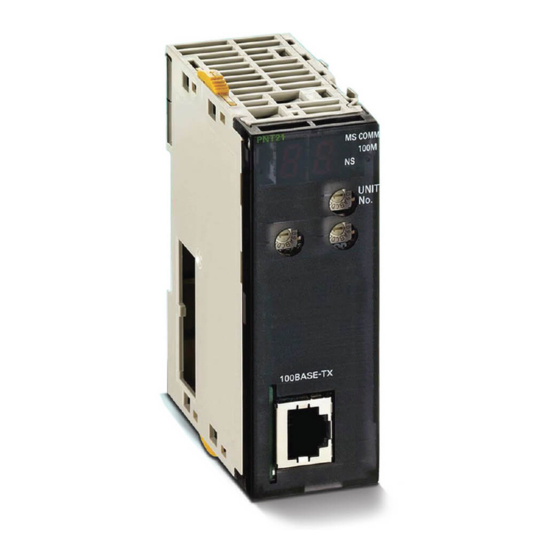
Page 57: Unit Components
(B) and the PROFINET IO Ethernet connector (C) on the front side of the CJ1W- PNT21 Unit. Each of these components is explained in the following sections. Indicators The CJ1W-PNT21 PROFINET IO Controller Unit uses the following indicators: • Four status indicators • Two 7-segment displays to show extra information •... - Page 58 2 Nomenclature and Installation Status Indicators: MS, NS, COMM and 100M Indicator Color State Description MS (Module Status) Green Initialization successful, unit is in normal operation Flashing No connection to the Ethernet Network, but initialization was successful. A non-recoverable, fatal error has occurred.
-
Page 59: Switch Settings
2 Nomenclature and Installation Seven-Segment Indicator In addition to the MS and NS indicators, PROFINET IO Controller Units have a 2-digit, 7-segment indicator. There are dot indicators at the lower-right corner of each digit. Seven-segment Digits Status Display IO Controller in normal operation Displays character “r”... - Page 60 PROFINET network. • After correcting the unit number setting, cycle the power to the Controller. • The two lower rotary switches are reserved for future use. Ethernet Connector The CJ1W-PNT21 has on Ethernet port. Signal Abbreviation Signal Direction...
- Page 61 2 Nomenclature and Installation Additional Information The following standards and specifications apply to the Ethernet connector and the twisted-pair cable. • Electrical specifications: Conforming to IEEE 802.3 standards • Connector structure: RJ45 8-pin Modular Connector (conforming to ISO 877). For more infor- mation about connectors see the PROFINET Cabling and Interconnection Technology Guide- line Order No.: 2.252 available through PI (Profi International).
-
Page 62: Installing The Profinet Io Controller Unit
2 Nomenclature and Installation Installing the PROFINET IO Controller Unit 2-2-1 System Configuration Precautions You can mount up to 16 Units on the CPU Rack or an Expansion Rack per CPU (but no more than 10 Units on one Rack). 2-2-2 Mounting Carefully align the connectors to mount the PROFINET IO Controller Unit... -
Page 63: Handling Precautions
2 Nomenclature and Installation Precautions for Safe Use If the sliders are not securely locked, the PROFINET IO Controller Unit functions may not oper- ate sufficiently. To dismount the Unit, move the sliders to the “Release” direction. 2-2-3 Handling Precautions Always turn OFF the Controller before you mount or unmount a Unit or connect or disconnect cables. -
Page 64: External Dimensions
2 Nomenclature and Installation 2-2-4 External Dimensions CJ-series PROFINET IO Controller Unit Operation Manual for NJ-series CPU Unit (W511) -
Page 65: Network Installation
Line Network A line topology comprises multiple IO Devices connected in series. Many IO Devices, such as the Omron GRT1-PNT IO Device Unit have an Ethernet switch integrated in the Unit offering an easy way to interconnect all Devices. Advantages of the Line Topology •... - Page 66 2 Nomenclature and Installation Star Network The star topology is the most common topology for Ethernet networks. A central switch allows for com- munication between all connected devices. Advantages of the Star Topology • Flexible adding and removing of devices without changes in existing connections. •...
- Page 67 2 Nomenclature and Installation Tree Network The tree topology is a hierarchical combination of multiple star topology interconnected with each other. Advantages of the Tree Topology • Flexible adding and removing of devices without changes in existing connections. • Easy diagnostics of the network by default isolation. •...
-
Page 68: Mrp Ring Redundancy
The network requires an MRP manager to facilitate the redundancy. As an MRP client, there are no specific settings required for the Omron GRT1-PNT IO Device Unit. Please refer to the manual of the used MRP manager unit for details on how to set up and operate the MRP network. -
Page 69: Profinet Io Controller Redundancy
Normally the first IO Controller that signalled that the output data is valid will be in control of the outputs of the IO Device. OMRON can therefore only guarantee proper IO Controller redundancy operation if implemented with GRT1-PNT IO Devices. -
Page 70: Network And Controller Redundancy
2 Nomenclature and Installation 2-3-3 Network and Controller Redundancy When combining the PROFINET MRP ring redundancy and the IO Controller redundancy a control system with a high reliability can be achieved. Single points of failure should have no influence on the operation of the application. - Page 71 2 Nomenclature and Installation 2-16 CJ-series PROFINET IO Controller Unit Operation Manual for NJ-series CPU Unit (W511)
-
Page 72: Configuration Software
Configuration Software This section presents an overview of the configuration software and gives insight in the main aspects of defining a PROFINET IO configuration. 3-1 CX-ConfiguratorFDT ......... . . 3-2 3-1-1 Starting CX-ConfiguratorFDT . -
Page 73: Cx-Configuratorfdt
The DTM only contains very limited online diagnostics functions and online parameter setup is not possible. This section provides information about the use of the CJ1W-PNT21 PROFINET IO Controller DTM and the Generic I/O Device DTM. For the use of the GRT1-PNT SmartSlice PROFINET IO Device DTM please refer to the SmartSlice GRT1-Series PROFINET IO Communication Unit Operation Manual □□... -
Page 74: Installation Procedure For A Dtm
This section explains how to install the PROFINET IO Generic Device DTM software. Exit all other Windows-based programs. Double-click the file OMRON PNIOGenericDeviceDTM setup.exe. The setup program for the PROFINET IO Generic Device DTM will start. Select the preferred Language for the Setup and click OK. -
Page 75: Establishing The Profinet Io Network
3 Configuration Software 3-1-3 Establishing the PROFINET IO Network This section briefly describes how to create, connect and configure the PROFINET IO network using the CX-ConfiguratorFDT software and the Device DTM’s. More detail can be found in the following sec- tions. -
Page 76: Cx-Configuratorfdt Main Window
3 Configuration Software CX-ConfiguratorFDT Main Window At first start up, the main application window of CX-ConfiguratorFDT opens with a New Project and the Device Catalogue is opened automatically. The Device Catalogue can also be opened from the menu. The figure below shows the opened CX-ConfiguratorFDT main window for a project already containing a defined network with the Device Catalogue window opened. - Page 77 3 Configuration Software The highest level of the tree is the project. The next level is the network controller level. On this level one or more Controller or master devices can be allocated. For example PROFINET IO Controllers. The third level contains the device DTM’s. These can only be the devices that can connect to that particular network master.
- Page 78 3 Configuration Software Menu Command Shortcut Key Description View Full Screen CTRL-ALT-F Switches the window to full screen view on the main display Network View Hides or un-hides the Network view Device Catalog Hides or un-hides the Device Catalogue Status Bar Hides or un-hides the Status bar Error Log Hides or un-hides the Error logging window...
-
Page 79: Device Catalog
3 Configuration Software Icon Description Equivalent menu command Uploads the parameters from the device. Device-Upload Parameters Opens the Device Catalogue. View-Device Catalogue Status Bar The status bar displays the current user role, that is the login level. In case the Error Log view has been closed, the status bar will additionally display a symbol to indicate that new errors are available in the Error Log view. - Page 80 3 Configuration Software Device name File date DTM categories Version number Vendor name Install a new GSD file Update Device Catalogue Add selected device to the network Invoking the Device Catalog The Device Catalogue window is opened by either selecting the icon in the CX-Configura- torFDT toolbar or by selecting View - Device Catalogue from the menu.
- Page 81 3 Configuration Software Additional Information The list makes no distinction between normal DTMs and GSDML files which have been loaded through the Generic IO Device DTM. When both DTM and GSDML are available for one device, it is recommended to use the DTM. ...
-
Page 82: Adding Devices To The Network
The device DTMs as listed in the Device Catalogue can be added to the network in three ways: Using the context menu A context menu will pop up when selecting the CJ1W-PNT21 PROFINET IO Controller DTM and then right clicking the mouse. By selecting the menu option Add Device, a simplified Device Catalogue is displayed showing only the DTMs which are allowed to be added to the PROFINET IO Controller DTM. -
Page 83: Saving And Opening Projects
3 Configuration Software Using the Drag & Drop function A Device DTM listed in the standard Device Catalogue window can be dragged and dropped from the Device Catalogue to a desired position in the Network view. Using the Add Device button A device DTM selected in the Device Catalogue can be added to a selected Master DTM in the Network view by clicking the Add Device button in the Device Catalogue window. -
Page 84: Error Logging And Fdt Monitoring
3 Configuration Software Right click the DTM to bring up the context menu. Select the Export to HTML option from the context menu. A window will pop up displaying the progress of the export process. When finished, CX-Configura- torFDT will launch the default browser to display the result. In this case, however, no links will be available to other DTMs in the network. -
Page 85: Access Control And User Management
The message may include the name of the DTM involved in the communication. The figure below shows an example of an FDT Monitoring message sequence. This example sequence is generated when opening a CJ1W-PNT21 PROFINET IO Controller Unit DTM. Right-clicking in the Error Log view displays a context menu providing the options listed below. - Page 86 3 Configuration Software The access rights per level are defined in the table below. Function Observer Operator Maintenance Planning Engineer Administrator New file Allowed Allowed Allowed Allowed Allowed Open file Allowed Allowed Allowed Allowed Allowed Save File Not allowed Not Allowed Allowed Allowed allowed...
- Page 87 3 Configuration Software Changing Access Rights By selecting the check box next to a level, the administrator can grant access rights to CX-Configu- ratorFDT, i.e. the checked levels can start and access CX-ConfiguratorFDT. If a check box is not selected, the corresponding level can not be used to start CX-ConfiguratorFDT and it will not appear in the drop down list in the login window.
- Page 88 3 Configuration Software The Administrator level has always access and can not be disabled in the User Accounts window. Changing the Passwords In order to change a specific password, select the Change password button in the User Account window, next to the related access level. The level must be enabled by selecting the check box to the left of it.
-
Page 89: Profinet Io Controller Dtm
3 Configuration Software PROFINET IO Controller DTM To allow configuration and data monitoring from within CX-ConfiguratorFDT a CJ1W-PNT21 PROFI- NET IO Controller DTM is installed. The DTM shows up in the Device Catalogue under the following name: Description Functions CJ1W-PNT21 PROFINET IO Controller •... - Page 90 3 Configuration Software Configuration Interface Buttons Master DTM Configuration User Interface The IO Controller DTM Configuration User Interface contains five main items. • PROFINET Identification • Configuration • Diagnosis • Firmware • DTM Information The five items are discussed below. ...
-
Page 91: Profinet Identification
3 Configuration Software 3-3-2 PROFINET Identification The PROFINET Identification item is used to detect and setup the names of the PROFINET IO Devices on the network. The PROFINET Identification item has only one sub-item: • Network Scan The sub-item is described in the section below. Network Scan In the Network Scan sub-item the following settings and operations must be done prior to starting PRO- FINET IO Communication. -
Page 92: Configuration
3 Configuration Software Control Description Search Devices The Search Devices button initiates a scan of the network and shows all found PROFINET IO Devices in the Network Scan View. For each device the MAC Address, Device Type, the currently assigned name and IP Address are dis- played. - Page 93 3 Configuration Software Each sub-item is described in the sections below. PLC Setup The PLC Setup sub-item provides the controls to establish communication between the PC and the PROFINET IO Controller Unit. The PLC Setup allows setting of the unit number to identify the PRO- FINET IO Controller Unit on the CPU system.
- Page 94 Controller Unit, after pressing the test button. Item Description Description Displays the name of the Unit, that is CJ1W-PNT21 Firmware Version Displays the firmware version of the PROFINET IO Controller Unit. PLC Mode The PLC Mode Box contains information and gives the user the opportunity to change the CPU mode.
- Page 95 3 Configuration Software Item Description Name This string is the PROFINET IO name of the Unit. IP Address This is the IP Address the PROFINET IO Controller Unit will use to setup communication to PROFINET IO Devices and on which the PROFINET IO Controller will be accessible from the Ethernet network.
- Page 96 3 Configuration Software The Device Name entered must be equal to the name that was given to the IO Device in the network Scan in the PROFINET Identification screen. If there is a mismatch the IO Controller can not estab- lish a connection.
- Page 97 3 Configuration Software IO Device Area The IO Device Area displays the mapping of the I/O data of the allocated IO Devices onto the CPU memory areas. The mapping can be made automatically or be changed by the user prior to down- loading.
- Page 98 CJ1W-DRM21 Devicenet Master/Slave Unit and in the CJ1W-PRM21 PROFIBUS Master unit. Care should be taken to avoid data overlap if such a Unit is part of the same CPU system as the CJ1W-PNT21 PROFINET IO Controller Unit. Mapping Area Control Each mapping Area in the Allocation tab is equipped with four controls and an information field located below the Area.
-
Page 99: Diagnosis
3 Configuration Software 3 Before compressing, the IO Controller DTM will display a warning message prompting the user for confirmation of the action. Changing Mapped Data Allocations By default, the data is mapped to Area 1 in both the Output and Input Allocation tabs. It is however possible to map a part of the data to the second area in the same tab. - Page 100 3 Configuration Software The status information is read from the Device Variables *_CtlrSta, *_UnitSta and *_IoDevSta. See 4-2 Device Variables for CJ-series Unit (Software Switches, Statuses) for more information. IO Device Status The IO Device Status presents an overview of the IO Devices that are in active Data Exchange or have the New Alarm flag raised.
- Page 101 3 Configuration Software Error History The Error History shows the Error Log of the PROFINET IO Controller Unit. For troubleshooting refer to this Error Log. 3-30 CJ-series PROFINET IO Controller Unit Operation Manual for NJ-series CPU Unit (W511)
-
Page 102: Firmware Upgrade
3 Configuration Software Firmware Upgrade In the rare occasion a firmware upgrade is needed for the CJ1W-PNT21 PROFINET IO Controller this can be done in the Firmware Upgrade item. The IO Controller DTM must be set online to perform the upgrade. -
Page 103: Generic Io Device Dtm
When this file is downloaded into the IO Controller it can perform I/O Data-exchange with the IO Devices. Apart from the configuration of OMRON PROFINET IO Devices by a DTM, OMRON provides the possi- bility to use GSDML files to allow configuration of third-party PROFINET IO Device Units, if a DTM is not provided. -
Page 104: Installing Gsdml Files
3 Configuration Software 3-5-2 Installing GSDML Files Install Device Description File The Device Catalogue window contains an Install Device Description File button. Clicking the button opens a file selection box from where different types of files can be imported. Only GSD-files for PRO- FIBUS devices and GSDML files for PROFINET IO Devices can be selected. - Page 105 A list of available modules is read from the GSDML file of the IO Device. The figure below shows an example of a module selection for a Omron GRT1-PNT PROFINET IO Device. Defining the I/O Configuration...
- Page 106 • Analog Units normally occupy 1, 2 or 3 words. To further explain the mapping sequence, an example is given below. The example is based on the Omron GRT1-PNT PROFINET IO Device. Example To illustrate how the Digital and Analog SmartSlice I/O Units are mapped to I/O words, and how to...
- Page 107 3 Configuration Software 3-36 CJ-series PROFINET IO Controller Unit Operation Manual for NJ-series CPU Unit (W511)
-
Page 108: Data Exchange With The Cpu Unit
Data Exchange with the CPU Unit This section describes the words allocated to the PROFINET IO Controller Unit in the CIO Area and DM Area. These words both enable controlling the Unit and accessing Unit and network status. 4-1 Data Exchange with the CPU Unit ....... . 4-2 4-1-1 Data Flow . -
Page 109: Data Flow
4 Data Exchange with the CPU Unit Data Exchange with the CPU Unit Data exchange between this Unit and the CPU Units uses the I/O port and memory for CJ-series Unit allocated to the PROFINET IO Controller Unit. 4-1-1 Data Flow The CPU Units and CJ-series PROFINET IO Controller Units exchange data as shown in the table and chart below. - Page 110 4 Data Exchange with the CPU Unit PROFINET I/O CPU Unit Controller Unit I/O port User program Software switch, Software switch, status data status data Software switches (I/O refresh) Device variable AT specification for CJ-series Unit Status (I/O refresh) Slave detailed IO Device status data Allocations setting table...
-
Page 111: Accessing From The User Program
4 Data Exchange with the CPU Unit Device Variable for CJ-series Unit Device variables for CJ-series Units are variables for which AT is specified for the I/O port explained below. The user program uses device variables for CJ-series Unit to access the configuration of the PROFINET IO Controller Unit. - Page 112 4 Data Exchange with the CPU Unit How to Create Device Variable for CJ-series Unit Use I/O Map in Sysmac Studio to allocate device variables for CJ-series Unit to an I/O port. Specify variable names using one of the methods shown below. 1.
- Page 113 4 Data Exchange with the CPU Unit A 4 point Input Unit and 4 point Output Unit are configured for use with the SmartSlice GRT1-PNT I/O bus coupler as shown above. CJ-series PROFINET IO Controller Unit Operation Manual for NJ-series CPU Unit (W511)
- Page 114 4 Data Exchange with the CPU Unit Words allocated I/O data CIO 3200 OUT device I/O data (Device Number 1) CIO 3300 GRT1-PNT Communication Unit Status (Device Number 1) CIO 3301 IN device I/O data (Device Number 1) Allocate the I/O data to the user-defined variables as shown in the example below. Additional Information For details on memory used for CJ-series Unit, variable allocation, and user-defined variable registration, refer to Sysmac Studio NJ-One Version 1.0 Operation Manual (Cat.
-
Page 115: Device Variables For Cj-Series Unit (Software Switches, Statuses)
4 Data Exchange with the CPU Unit Device Variables for CJ-series Unit (Software Switches, Statuses) When you operate and reference software switches and statuses, use the following device variables for CJ-series Unit allocated to the I/O port of this Unit. Name of device variable Type Area... -
Page 116: Unit Status
4 Data Exchange with the CPU Unit Name of device variable Type Area Function for CJ-series Unit *_ClrAllAlmCmd BOOL Clear all alarm The clear alarm bits switch will clear all alarm bits flags for all IO Devices. It is rising edge trig- gered. - Page 117 TRUE: Turned ON by the Unit if an error occurred during the storage of the data trans- ferred from the configuration software to the CJ1W-PNT21 non-volatile memory. If the error occurred, the data in the non-volatile memory may be corrupted and a new Configura- tion must be downloaded to the Unit.
-
Page 118: Io Controller Status 1
4 Data Exchange with the CPU Unit Name of device variable Type Area Function for CJ-series Unit *_ParamLoadErr BOOL Local parame- FALSE: Turned OFF by the Unit if the Configura- ter load error tion and setup data has been transferred from non-volatile to volatile memory. - Page 119 TRUE: Turned ON by the Unit if it is currently in ONLINE mode. In this case *_OfflineSta will be OFF. ONLINE means that the CJ1W-PNT21 is capa- ble of communicating on the network. The unit can not communicate on the network if hardware errors occur during startup or normal operation.
-
Page 120: Io Device Status
4 Data Exchange with the CPU Unit 4-2-4 IO Device Status The following device variable for CJ-series Unit is used to reference all information of IO Device Status. Name of device variable Type Area Function for CJ-series Unit *_IoDevSta WORD IO Device Sta- Bit 00: All Devices are in Data Exchange Bit 01: All IO Devices have consumed output... -
Page 121: Io Device Input Valid Flags
4 Data Exchange with the CPU Unit 4-2-5 IO Device Input Valid Flags The following device variables for CJ-series Unit are used to reference individual information. Array elements of *_DevInDataValid[1 to 126] correspond to IO Device station numbers 1 to 126. The bits for station 0 and 127 are not used. -
Page 122: Io Device New Alarms Flags
4 Data Exchange with the CPU Unit 4-2-6 IO Device New Alarms Flags Name of device variable Type Area Function for CJ-series Unit *_DevAlm BOOL IO Device New Array elements of *_DevAlm[1 to 126] corre- Alarm spond to IO Device station numbers 1 to 126. The bits for station 0 and 127 are not used. - Page 123 4 Data Exchange with the CPU Unit 4-16 CJ-series PROFINET IO Controller Unit Operation Manual for NJ-series CPU Unit (W511)
-
Page 124: Operation
Operation This section describes how to operate the CJ1W-PNT21 PROFINET IO Controller Unit in a Network. It will discuss setting up a network, configuring all the connected devices and starting the network. Furthermore, it provides information the I/O data exchange performance and it also provides information on how to monitor a network using the Unit and CX-ConfiguratorFDT. -
Page 125: Configuring A Network
Start CX-ConfiguratorFDT Configuring a network involves creating a system in CX-ConfiguratorFDT and downloading it to the PROFINET IO Controller Unit. To start CX-ConfiguratorFDT, select Program, OMRON, and CX- ConfiguratorFDT from the Start Menu if the default program folder name is used. -
Page 126: Adding Devices To The Network
If the Device Catalogue is current it can be used to setup the network. Configuring a network in CX- ConfiguratorFDT starts with adding single device DTMs to the Network view. First the CJ1W-PNT21 IO Controller DTM must be added to the main branch of the project Network. To do so, one of the three procedures outlined below must be used to add the DTM. - Page 127 5 Operation A simplified Device Catalogue is displayed. The list only contains the devices which can be inserted at the selected network location (see figure below, only master devices are listed). From the displayed list, select the device DTM to be added and select the OK button. The Device DTM will be added to the network.
-
Page 128: Setting Io Device Names
5 Operation • When adding a CJ1W-PNT21 IO Controller DTM to the network, it is automatically assigned the IP address 192.168.0.100. This address can be changed, after opening the CJ1W-PNT21 IO Controller DTM. After adding the Master DTM to the Network view, repeat (one of) the pro- cedures as outlined above to add slave DTMs to the Master DTM. - Page 129 5 Operation • Signal will let the indicators of the selected device flash for 3 seconds. This is useful to physically find the device in the installation. When found the device can get a logical name. • Set IP Address... will set the IP Address of the selected device. The IP Address can be fixed or temporary.
-
Page 130: Configuring The Io Devices
5 Operation Configuring the IO Devices After adding each of the IO Device DTMs to the network, configurations have to be selected for each of them. Setting up a configuration involves: • Selecting the proper I/O modules, which define the I/O data to be exchanged when operational. •... - Page 131 Depending on the device, the sequence may be checked by the IO Device. If an incorrect sequence is sent, the I/O configuration is rejected. This is for example the case with the OMRON GRT1-PNT PROFINET IO Device Note A mandatory I/O module sequence is sometimes indicated in the GSDML file by using non- PROFINET standard GSDML file keywords (i.e.
-
Page 132: Configuring The Io Controller
• Select the CJ1W-PNT21 IO Controller DTM in the Network view and double-click the left mouse button. • Select the CJ1W-PNT21 IO Controller DTM in the Network view, and right click the mouse. From the context menu, select Configuration. • Select the CJ1W-PNT21 IO Controller DTM in the Network view, and from the Device menu, select Configuration. -
Page 133: Io Controller Setup
5 Operation Unit Number The setting of the unit number is required to setup communication with the Unit through CX-Server. The setting in the user interface must match the setting made with the rotary switch on the front of the Unit. -
Page 134: Io Device Setup
Gateways, however are not supported. Auto-Addressing Auto-Addressing defines whether or not the CJ1W-PNT21 IO Controller DTM will automatically map the I/O data in such a way that no gaps exist in the I/O data. If enabled, the user does not need to manage the exact mapping of I/O data to the CPU memory areas. -
Page 135: Io Device Area
5 Operation • In the IO Device Input Valid (*_DevInDataValid) and New Alarm flags areas (*_DevAlm). • Reading New Alarms from the IO Controller. • Message routing through the IO Controller to determine Device address and IP address. Device Name The Device Name is the name set in the IO Device in the Network Scan sub item in the PROFINET Identification. -
Page 136: Mapping I/O Data
I/O modules are moved from one area to another, the I/O modules in first Area are re- mapped to close all the gaps between mappings. 2 Prior to download, the CJ1W-PNT21 IO Controller DTM will check the mappings for possible Area overlaps, CPU memory overlaps and non-existing EM banks. If an error is detected, download will be aborted and the necessary correction must be made first. - Page 137 • Slave device 3: One output module. • Slave device 4: Two input modules. The CJ1W-PNT21 PROFINET IO Controller Unit, will assemble the correct PROFINET data mes- sages from the storage order in the Input and Output memory areas. Additional Information •...
- Page 138 The default allocation of I/O modules, (i.e. I/O modules are mapped in ascending order of IO Device No. and module selection) uses the concept of Auto Addressing of the CJ1W-PNT21 IO Controller DTM. Auto Addressing will (re)allocate I/O modules according to the algorithm explained above in each area.
- Page 139 Input/Output area. This can be accomplished by using drag & drop to move the I/O modules. To accomplish this, perform the following sequence: Open the CJ1W-PNT21 IO Controller DTM - Configuration User Interface. Select the IO Device Area sub item. The window shows two sub tabs: One for Output Allocation and one for Input Allocation.
- Page 140 I/O modules are allocated to the lowest address of the area. Enable/Disable Auto Addressing The Auto Addressing feature can be disabled in the CJ1W-PNT21 IO Controller DTM by performing the following sequence. Open the CJ1W-PNT21 IO Controller DTM - Configuration User Interface.
- Page 141 5 Operation Additional Information Disabling Auto Addressing has no immediate effect on an existing I/O mapping. I/O Mapping Without Auto Addressing A disabled Auto Addressing feature has the following effects on I/O mapping. • When adding new IO Devices or new I/O modules to an existing configuration, the I/O mod- ules will be mapped to the first I/O areas but the modules will be appended to the existing I/O mapping.
- Page 142 5 Operation Removing Gaps from the I/O Mapping Since gaps in the I/O mapping are generally undesirable, the CJ1W-PNT21 IO Controller DTM pro- vides a means to remove all gaps after finalizing the I/O mapping procedure. This removal is accom- plished by compressing the I/O modules in a particular area.
- Page 143 Additional Information • The CJ1W-PNT21 IO Controller DTM will check whether two or more selected mappings to the CPU memory will be overlapping. In that case, the start address set will be shown in red. • If any mapping error is discovered by the Master DTM, an error message is displayed and download is terminated.
-
Page 144: Supported Data Types And Conversion
5-3-6 Supported Data Types and Conversion The CJ1W-PNT21 PROFINET IO Controller Units perform an interface function between a PROFI- NET IO network and the NJ CPU. On both sides of the interface different formats for data and data storage are used. - Page 145 5 Operation Size Data Type PROFINET IO NJ-series Controller [bytes] TimeOfDat without date indica- Supported Supported tion Data is transmitted on a Most-Signifi- Single 16-bit integers are trans- cant- Byte First basis ferred to memory words in CPU memory. TimeDifference Supported Supported Data is transmitted on a Most-Signifi-...
- Page 146 5 Operation The following format conversions are required: • A sequence of 8-bit bytes, either signed or unsigned must be mapped to the CPU data area words on a low-byte/high-byte sequence. If the number of bytes is even, all bytes will fit in the words.
- Page 147 5 Operation The following format conversions are required: • On the PROFINET IO network, the text strings are handled as a sequence of 8-bit bytes, but the storage in the CPU data area is following the (unsigned 16-bit) word storage method, i.e. the bytes are stored in a high-byte/ low-byte sequence.
-
Page 148: Performance
5 Operation Performance As specified, the CJ1W-PNT21 IO Controller can cyclically exchange I/O data with up to 126 PROFI- NET IO Devices. The rate at which it can service IO Devices depends on the number of connected devices and the size and complexity of the data. Especially with modular IO Devices, the IO Controller needs time to pack and unpack the I/O data of each device module and convert them to the correct rep- resentation in the CPU. - Page 149 5 Operation Additional Information • The maximum of 55 devices in maximum configuration is caused by the reaching the limit of 7168 Words that the IO Controller can exchange with the CPU. • The maximum number of IO Devices that the IO Controller supports is 126. 5-26 CJ-series PROFINET IO Controller Unit Operation Manual for NJ-series CPU Unit (W511)
-
Page 150: Operating The Network
DTM Diagnosis User Interface may interfere with a CPU user program running at the same time. This can result in unexpected behavior. It is recommended to change the CPU mode to PRO- GRAM mode to avoid this interference during the use of the CJ1W-PNT21 IO Controller DTM Diagnosis User interface. - Page 151 5 Operation The Output Data state is CPU Mode Dependent. If the CPU is in Program mode then the Output Data is marked as invalid. If the CPU is in Run mode then the Output Data is marked as valid. The Output Data state is controlled by a Device Variable (*_OutDatValCmd) The Set Output Data Valid bit sets the state of the output data.
- Page 152 Message Communications This section describes message communications using commands sent from the user program in the CPU Unit. 6-1 Overview ........... . . 6-2 6-2 Sending Acyclic Messages Using SendCmd Instructions .
-
Page 153: Overview
• Message commands targeted at the Unit itself with the purpose of sending or retrieving data or invok- ing control actions (0101, 2102, 2103). • Explicit messages targeted at IO Devices such as the GRT1-PNT Unit (2801) The figure below depicts the message command structure for the CJ1W-PNT21 PROFINET IO Control- ler units. PROFINET I/O... - Page 154 • PROFINET Network Number: 2 NJ series CPU Unit CJ1W-PNT21 Unit No.: 0 SendCmd CJ1W-PNT21 Device Number: 0 CJ1W-PNT21 Unit address: 11 Hex Explicit message GRT1-PRT Communication Unit Device Number: 65 CJ-series PROFINET IO Controller Unit Operation Manual for NJ-series CPU Unit (W511)
- Page 155 6 Message Communications Command source Destination Sdata[0] Sdata[1] SendCmd Execute Done Sdata[7] Command code DstNetAdr Busy interpretation Sdata[8] CommPort Error ErrorID CmdDat ErrorIDEx CmdSize Rdata[0] Execution RespDat RespDat Rdata[1] Option Rdata[8] Rdata[9] Input Variable Function Example Details Execute The operation SendCmd is executed when TRUE is set. DstNetAdr The destination network address is specified with the use of Network address: 2...
- Page 156 6 Message Communications Additional Information You can send acyclic messages to OMRON slaves by setting the command code to 28 01. In this case, set the response monitoring time to at least the value set for the message monitor- ing timer (default: 2s). If it is set to less than the value, communications may be busy even if the next command is executed after the first one times out.
- Page 157 6 Message Communications Determining the SendCmd instruction execution completion SendCmd_instance.Done OperatingEnd SendCmd_instance.Error Trigger reception RS_instance Operating _Port_isAvailable Trigger PNT21_AllDatXchgSta OperatingEnd Reset1 Communications parameters settings Operating InDNetAdr.NetNo:=2; // Network address settings InDNetAdr.NodeNo:=65; InDNetAdr.UnitNo:=BYTE#16#00; InOption.isNonResp:=FALSE; // Response monitoring and retry settings InOption.TimeOut:=60; InOption.Retry:=0;...
-
Page 158: Explicit Message Send (2801)
PROFIBUS DP-V1 slave device during regular I/O data exchange. 6-3-1 EXPLICIT MESSAGE SEND (2801) Sends an explicit message over the PROFINET network to an OMRON slave device (GRT1 SmartSlice for example) and receives a response. Explanation The Explicit Message Send command sends a CIP-defined explicit message to an OMRON PROFI- NET Slave device supporting CIP messages. - Page 159 6 Message Communications Command Response No. of bytes Error code code code received Service code 94 (Hex) Source station address (local node) For the definition of the error codes for unsuccessful execution of CIP messages, refer to the Smart- Slice GRT1-Series GRT1-PNT PROFINET Communication Unit Operation Manual (Cat No. W13E- □□...
- Page 160 6 Message Communications Instance ID (Command) Specifies the instance ID for the explicit message destination. The supported Instance ID values are specified in the Operation manual of the targeted slave device. Service Data (Command, response) For commands, specifies the data defined by the service code. For responses, returns the reception data defined by the service code.
-
Page 161: Memory Area Read (0101)
The following end codes can be returned by the Unit in response to the MEMORY AREA READ command: Response code Description 0000 Normal completion. 0101 IO Device not allocated to this CJ1W-PNT21. 1001 Command length exceeded. 1002 Command length too short. 1101 Invalid I/O memory area code (non-specified code). -
Page 162: Error Log Read (2102)
6 Message Communications Response code Description 0001 Status error. Additional Information The IO Device address is the Device No. assigned in the IO Controller DTM configuration item, IO Device setup sub item. This address is used to determine the IO Device. See 3-3-3 Configu- ration for details. - Page 163 6 Message Communications Maximum Number of Stored Records (Response) The maximum number of records that can be stored in the error log. In a PROFINET IO Controller Unit, the maximum number of stored records is fixed at 50 (80 decimal). Number of Stored Records (Response) The number of records stored at the time the command is executed.
-
Page 164: Error Log Clear (2103)
6 Message Communications 6-3-4 ERROR LOG CLEAR (2103) The ERROR LOG CLEAR command clears the number of records stored in the PROFINET IO Control- ler Unit Error Log. Command Format Command code Response Format Command Response code code ... -
Page 165: Command Message Routing
In the example above the highest IP-address is 192.168.1.127. Performance The CJ1W-PNT21 PROFINET IO Controller’s main task is PROFINET IO communication. The com- mand message communication is performed as a low priority task. This means that the command message communication performance is low. Also, the IO Controller can only handle one command message at a time. -
Page 166: Troubleshooting And Maintenance
Troubleshooting and Maintenance This section describes error processing, periodic maintenance operations, and trouble- shooting procedures needed to keep the PROFINET network operating properly. We recommend reading through the error processing procedures before operation so that operating errors can be identified and corrected quickly. 7-1 Troubleshooting with the PROFINET IO Controller Unit Indicators . -
Page 167: Troubleshooting With The Profinet Io Controller Unit Indicators
7 Troubleshooting and Maintenance Troubleshooting with the PROFINET IO Controller Unit Indicators 7-1-1 Determining Operating Status from the Indicators This section presents a number of easy to use procedures to troubleshoot possible errors using the indicators on the front of the Unit. The indicators on the PROFINET IO Controller Unit have the following functions: Indicator Indicating... -
Page 168: Troubleshooting Errors Occurring In The Profinet Io Controller Unit
7 Troubleshooting and Maintenance Indicator Status Network/Unit sta- Comments 100M 7-segment Booting and intial- Bootup and intialization with the CPU in izing with the CPU progress. Restart the PROFINET IO Controller Unit if the status continues for an extended period of time. Replace the CPU Unit and/or PROFINET IO Control- ler Unit if the problem is not corrected by restarting. - Page 169 7 Troubleshooting and Maintenance Indicators Error category Error Error log (Hex) 7-segment CPU Unit Bus error Flashing (red) OFF 000E Exchange Unit number duplication CPU Unit faulty I/O table not registered CPU Unit service monitoring error 0001 CPU Unit watchdog timer error 0002 Additional Information If Module Status is Red lit or flashing then refer to the displayed error code on the 7- segment...
- Page 170 7 Troubleshooting and Maintenance PROFINET Network Errors Ethernet Failure Error log Likely cause Unit response Device Variable Flag Correction (Hex) 020C The PROFINET IO Controller The Unit is not capable to (IO Controller status 2) Check the Ethernet cable could not establish a Ethernet communicate on the *_HwErr will be TRUE.
- Page 171 7 Troubleshooting and Maintenance CPU Unit Exchange Bus Error Error log Likely cause Unit response Device Variable Flag Correction (Hex) 000E The PROFINET IO Controller The IO Unit will stop pro- None of the bits are set. Restart the CPU. Check encountered an error while cessing.
- Page 172 7 Troubleshooting and Maintenance Watchdog Timer Error Error log Likely cause Unit response Device Variable Flag Correction (Hex) 0002 The PROFINET IO Controller The Unit will stop pro- None of the bits are set. Replace the CPU Unit if detected a watchdog timer cessing.
-
Page 173: Troubleshooting The Network
If no errors occurred during the checking phase, the IO Controller DTM will try to establish communi- cation with the CJ1W-PNT21 PROFINET IO Controller Unit through CX-Server. If this fails, an error message will be displayed, indicating a communication problem. A failure to establish communica- tion prior to download will have no consequences for the CJ1W-PNT21 PROFINET IO Controller Unit. -
Page 174: Troubleshooting The Network Using Cx-Configuratorfdt
7 Troubleshooting and Maintenance 7-2-2 Troubleshooting the Network using CX-ConfiguratorFDT CX-ConfiguratorFDT provides several means to troubleshoot either the CJ1WPNT21 PROFINET IO Controller Unit, the IO Devices or the network. The means all rely on features discussed in the pre- vious section. ... - Page 175 7 Troubleshooting and Maintenance Indicators Description/Correction File Read Error If the IO Controller restores a configuration from Compact Flash card in the CPU and it can not access the configuration file on the Compact Flash card then this flag is TRUE. *Limited memory card functionality based on CPU version.
- Page 176 7 Troubleshooting and Maintenance Indicators Description/Correction All IO Devices are in Data Exchange and The Unit could establish an connection to all configured IO Devices. All these IO providing valid input data Devices are now in Data Exchange and are providing valid input data. If one of the IO Devices sets it input data to be invalid then there could be some- thing wrong with that IO Device.
- Page 177 7 Troubleshooting and Maintenance Missing IO Devices will be marked will be marked Red. IO Devices that signalled an alarm will be Yellow. The standard PROFINET alarms are implemented: • Pull Module • Plug Module • Plug Wrong Module • Other When the type of Alarm is Other then additional information can be found in the Description and the Manufacturer Specific Data (Raw) fields.
-
Page 178: Cpu Unit's Err/Alm Indicator Lit Or Flashing
7 Troubleshooting and Maintenance 7-2-3 CPU Unit’s ERR/ALM Indicator Lit or Flashing Use the following table to troubleshoot the network when the DeviceNet Unit is mounted and the CPU Unit's ERR/ALM indicator is lit or flashing.’ Error Probable Cause An I/O setting check error occurred. •... -
Page 179: Event Logs
7 Troubleshooting and Maintenance Event Logs 7-3-1 Overview of the Event Logs The Event Log allows the user to access all of the events that occur on the NJ-series Controller includ- ing errors and information. You can use the Sysmac Studio or an NS-series PT to confirm current Con- troller events and the logs of events that have occurred. - Page 180 7 Troubleshooting and Maintenance Level Event code Event name Meaning Assumed cause Obs Info 18010000 Local parameter The setup data in • An error occurred during the storage of storage error non-volatile mem- the data transferred from the configura- ory may be cor- tion software to the Unit’s internal non- rupted.
- Page 181 7 Troubleshooting and Maintenance 7-3-3 Error Descriptions This section describes the information that is given for individual errors. Controller Error Descriptions The items that are used to describe individual errors (events) are described in the following copy of an error table. Event name Gives the name of the error.
-
Page 182: Error Descriptions
7 Troubleshooting and Maintenance Error Descriptions Event name Local parameter storage error Event code 18010000 hex Meaning The setup data in non-volatile memory may be corrupted. Source Function Module Source details CJ-series Unit Detection At parame- timing ter/configuration download to Unit. Error attributes Level Minor... - Page 183 7 Troubleshooting and Maintenance Effects User program Continues Operation Cannot load a valid configuration from the memory card and therefore cannot begin data exchange with IO Devices until a valid configuration is loaded from the memory card. System-defined Variable Data type Name variables *_FileRdErr...
- Page 184 7 Troubleshooting and Maintenance Event name Configuration Error Event code 38090000 hex Meaning One or more configuration errors have been detected. Source Function Module Source details CJ-series Unit Detection At power ON or timing reset. Error attributes Level Minor Recovery Error reset Log category System...
- Page 185 7 Troubleshooting and Maintenance Cause and cor- Assumed cause Correction Prevention rection No Ethernet cable is connected. Troubleshoot network connections for Ensure PROFINET network is con- faulty hardware and/or connection(s). forming to proper specifications. Damaged Ethernet cable or other net- work hardware.
-
Page 186: Maintenance And Replacement
7 Troubleshooting and Maintenance Maintenance and Replacement This section describes the routine cleaning and inspection recommended as regular maintenance as well as the Unit replacement procedure. 7-4-1 Cleaning Clean the PROFINET IO Controller Units regularly as described below in order to keep the network in its optimal operating condition. -
Page 187: Replacing Faulty Units
After configuring the new Unit, re-connect it to the network, and restart operation. Additional Information *_Sw2FileBkupCmd and *_Sw2FileRestoreCmd (Unit Setup File Backup and Restore Switches) are not supported with the CJ1W-PNT21 Unit when used with the NJ-series Controller Unit. 7-22 CJ-series PROFINET IO Controller Unit Operation Manual for NJ-series CPU Unit (W511) -
Page 188: Addition/Replacement Of Units On The Profinet Network
7 Troubleshooting and Maintenance 7-4-4 Addition/Replacement of Units on the PROFINET Network The PROFINET network allows to connect and disconnect devices while in operation. Connecting / Disconnecting Devices Connecting/disconnecting any device in a PROFINET network is liable to result in a temporary increase of the communication cycle time. - Page 189 7 Troubleshooting and Maintenance 7-24 CJ-series PROFINET IO Controller Unit Operation Manual for NJ-series CPU Unit (W511)
-
Page 190: Appendices
Appendices A-1 Differences in Available Functions Depending on the CPU Unit (NJ/CJ- series) to be Connected ........A-2 A-1-1 Differences in Available Functions . -
Page 191: Differences In Available Functions Depending On The Cpu Unit (Nj/Cj-Series) To Be Connected
Appendices A-1 Differences in Available Functions Depending on the CPU Unit (NJ/CJ- series) to be Connected A-1-1 Differences in Available Functions Some functions available to the CJ series may be unavailable when you operate this Unit with the NJ series. The following table lists the differences between the NJ and CJ series for each function that this Unit provides. - Page 192 Appendices CPU Bus Unit Words Allocated in CIO Area Word n (Software switches 1) The device variables for CJ-series Unit that corresponds to all bits of word n is as follows: NJ-series device vari- CJ-series I/O memory and NJ-series CJ Unit memory ables for CJ-series Unit Word number...
- Page 193 CJ1W-PNT21 PROFINET IO Controller function. Any errors in the behavior of the CJ1W-PNT21 are presented in the 'IO Controller status 2' word. The device variables for CJ-series Units that correspond to bits 0 to 31 of word n+5 and n+6 are as...
- Page 194 0 to 15 The IO Device status word presents all information *_IoDevSta on the IO Devices allocated to the CJ1W-PNT21 Controller. Detailed information on the IO Devices can be obtained by reading the alarm mes- sages. Contents of the 'IO Device status' word (Word...
- Page 195 Appendices NJ-series device vari- CJ-series I/O memory and NJ-series CJ Unit memory ables for CJ-series Unit Word number Bit number CJ-series function name Variable name n+9 to n+16 1 to 126 The IO Device Data Exchange Active flags indicate *_DevInDataValid for each IO Device if it is in Data Exchange mode with the PROFINET IO Controller Unit.
-
Page 196: A-2 Profinet Io Alarm Messages
Appendices A-2 PROFINET IO Alarm Messages A-2-1 Introduction PROFINET IO is capable of sending events within the automation process as alarms. These alarms have to be acknowledged by the application process. These include both system-defined events (i.e. Removal of slices) or userdefined events (i.e. Input voltage out of range). The following events are distinguished: Alarm Type Description... - Page 197 Appendices Byte Name Description 18 to 21 SubmoduleIdent The Ident number of the subslot. 22 to 23 Specifier The specifier of the alarm. The following bits are defined. • Bit 0 to 10: Sequence number • Bit 11: Channel Diag exists (value 1 is exists) •...
- Page 198 Index CJ-series PROFIBUS Master Unit Operation Manual for NJ-series CPU Unit (W509) Index-1...
- Page 199 Index Index Numerics 100 Indicator ....... . . 7-2 Data Exchange ......1-3, 4-2 Data Exchange Configuration .
- Page 200 Index General Station Description ..... 1-4 MAC Address ......1-3, 5-5 General Sub-item .
- Page 201 Index Search Devices ......3-20, 5-5 Set Device Name ......3-21, 5-6 Set IP Address .
- Page 202 • Purchasing management, order record and tracking of shipments. To access the product, click on the green button. Product Code Reference Product link 291927 CJ1W-PNT21 Buy on EAN Control system, PROFINET-IO Controller Module 258404 GRT1-PNT Buy on EAN E / S Remote, Header Communications SmartSlice Profinet...
Need help?
Do you have a question about the CJ1W-PNT21 and is the answer not in the manual?
Questions and answers