Aidcall Touchsafe Pro Installation Manual
Wireless nursecall system, telecare receiver
Hide thumbs
Also See for Touchsafe Pro:
- User manual (38 pages) ,
- Installation manual (38 pages) ,
- Installation & user manual (23 pages)
Advertisement
Quick Links
Download this manual
See also:
User Manual
Touchsafe® Pro
Wireless Nursecall System
_________________________________________________________________________________________________
Aidcall operates a policy of continual product improvement and
reserves the right to modify the specification of its products.
If any variation to the details in this document are suspected please
contact Aidcall's Technical Support.
Aidcall, a business unit of Legrand Electric Ltd
Cowley Road, Blyth Riverside Business Park, Blyth, Northumberland, NE24 5TF.
T: +44 (0) 1670 357 431 www.aidcall.co.uk
________________________________________________________________
Telecare Receiver (TCR)
Installation Guide
Doc No. FM5565 issue B Page 1
Advertisement

Subscribe to Our Youtube Channel
Related Manuals for Aidcall Touchsafe Pro


Summary of Contents for Aidcall Touchsafe Pro
- Page 1 Aidcall operates a policy of continual product improvement and reserves the right to modify the specification of its products. If any variation to the details in this document are suspected please contact Aidcall’s Technical Support. Aidcall, a business unit of Legrand Electric Ltd Cowley Road, Blyth Riverside Business Park, Blyth, Northumberland, NE24 5TF. T: +44 (0) 1670 357 431 www.aidcall.co.uk ________________________________________________________________ Doc No. FM5565 issue B Page 1 ...
-
Page 2: Table Of Contents
1. PRODUCT OVERVIEW Touchsafe Pro Telecare Receivers (TCR’s) provide the interface between Telecare radio devices and the Nursecall system. A maximum of 32 TCR’s can be installed per site. All TCR’s require connection to the Master Panel (ID1) RS485 data bus and a separate 12V DC battery backed power supply. Multiple PSU’s may be required on large installations. Note: if AVI’s are installed then TCR’s can be powered from the AVI PSU’s provided care is taken not to exceed the PSU rating. An extensive range of Telecare devices are available to personalize the Nursecall system to specific needs of staff and patients. For personal wellbeing there are devices to detect falls, bed occupancy, chair occupancy, wandering, personal attack and epilepsy. For environmental monitoring there are devices to detect smoke, heat, gas, carbon monoxide, flood and high/low room temperatures. Please contact Aidcall customer services for full details of all devices available and there applications. Doc No. FM5565 issue B Page 2 ... -
Page 3: Important Safety Instructions
2. IMPORTANT SAFETY INSTRUCTIONS Read and understand these instructions before use. Keep these instructions for future reference. Take care when working on step ladders during installation or service. Do not disassemble this product or attempt to repair it yourself. No user serviceable parts inside. Refer all servicing to qualified service personnel. This product should only be powered by a separate 12V DC battery backed PSU. Danger of explosion if the PSU rechargeable battery is incorrectly replaced. Use only manufacturer approved battery as identified in this manual. Refer replacement to qualified service personnel. This product should be located at least 2 metres away from other electronic equipment. Failure to provide this separation may result in reduced radio range. Do not locate this product above a radiator or other heat source. Do not expose to direct sunlight. Do not submerge in water and do not use in damp or humid conditions. Do not expose this product to dripping or splashing water. Liquids can cause a failure and/or a fire hazard. Clean with a hard‐surface disinfectant wipe or a damp cloth and a non‐abrasive cleaning product. Polish with a dry duster. DO NOT use a wet cloth. Avoid using harsh, abrasive or corrosive cleaning agents or detergents (e.g. scouring powders, bleaches, polishes, etc.) when cleaning this product. At the end of its life this product should be disposed of and recycled in accordance with the environmental regulations. See the Regulatory Information in section 3 below. ... -
Page 4: Regulatory Information
3. REGULATORY INFORMATION This symbol on the product indicates it complies with all relevant EU Directives as required by law. Radio & Telecommunication Terminal Equipment; R&TTE Directive 1999/5/EC Safety of Information Technology Equipment; EN 60950‐1:2006+A12:2011 Electro Magnetic Compatibility; EMC 2004/108/EC Restriction of Hazardous Substances; RoHS 2011/65/EU A copy of the complete Declaration of Conformity is available from Aidcall. This symbol on the product indicates it is classed as Electrical or Electronic Equipment and should not be disposed of with other commercial waste at the end of its working life. The Waste of Electrical and Electronic Equipment (WEEE) Directive (2012/19/EU) has been put in place to recycle products using the best available recovery and recycling techniques to minimise impact on the environment, treat hazardous substances and avoid increasing landfill. For product disposal please contact your supplier and check the terms and conditions of the purchase contract and ensure this product is not mixed with other commercial waste for disposal. This symbol on batteries indicates separate collection. Batteries contain chemicals that can be hazardous to health and the environment and should not be disposed of in the waste bin. The EU Directive (2006/6/EC) has been put in place to ensure the safe disposal and recycling of batteries. Return used batteries to your supplier or drop‐off at your local municipal waste recycling depot. NTENTS 4. MAINTENANCE & CARE ... -
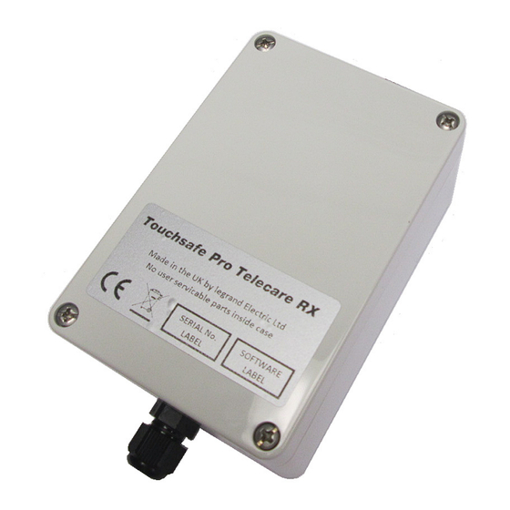
Page 5: Tcr Features
5. TCR FEATURES The key features of the TCR are identified below; Aidcall Part No. ZNC660 BNC Connector for Antenna Wall Mounted ABS Enclosure 120 x 80 x 55mm (HxWxD) ½ Wave Whip Antenna (900mm High) Screw‐on Lid Supplied with 1 metre RG58 Coax and Mounting Bracket Cable Entry Gland ... - Page 6 6. TCR INSTALLATION The total number and positioning of the TCR’s will be determined by site conditions; a typical indoor radio range of 75 metres radius can be expected. See the building plan below with 2 TCR’s giving full coverage; TCR’s give approx. 75 metres TCR 1 radius radio coverage TCR 2 Construction materials such as foil backed plasterboard, reinforced concrete or stone walls will reduce range. Environmental conditions such as high levels of transmission at nearby frequencies or emissions from other electrical equipment may further reduce range. Clear line‐of‐sight will give best range. RS485 BUS It is important that the RS485 data bus wiring network is connected in one continuous “daisy‐chain” through all TCR’s (plus optional Master Panel RFE and AVI’s) installed on the scheme… Master Panel Ext RFE Multiple AVI’s/TCR’s Last TCR ...
- Page 7 6. TCR INSTALLATION SITE WIRING TCR’s require a power and data connection on a 2 pair bus cable. The data connection must be taken from the RS485 Port on the Master Display Panel (ID 1) and is common to all TCR’s (and AVI’s) on the site. Up to 4 TCR’s can be powered from a 12V DC 1A battery backed PSU. TCR 1 TCR 2 TCR 3 TCR 4 Battery Backed 12V/1A PSU Local Mains Supply Power Cable 4 TCR’s can be powered per 12V/1A PSU ‐ max cable length 400 metres Up to 32 TCR’s can be fitted per site – these should be split over multiple power legs with a maximum of 4 TCR’s on 400 metres cable length per leg. The RS485 data must be connected in one continuous leg from the Master Panel (ID 1) – cable length should not exceed 1200 metres. ...
- Page 8 Pair No. Colour Terminal The drain wire is NOT connected. Red 12V 1 (Power) Do not cut‐off, sufficient length Black 0V should be left during installation for Green RS485+ possible future use. Ensure the 2 (Data) un‐used drain wire is well insulated. Drain Wire White RS485‐ This cable is available from Aidcall in 100m reels; Part No. YW1715. Doc No. FM5565 issue B Page 8 ...
- Page 9 6. TCR INSTALLATION CONNECTION DETAILS Connect the TCR data bus direct to the Master Panel (ID 1) as shown below; Bus Cable common to all TCR’s (Max 32) Connect RS485 IMPORTANT data from the Loop the RS485 Bus Cable once Master Panel (ID 1) through the Ferrite Sleeve provided with the Panel Connect the TCR power in groups of 4 from a separate 12V/1A PSU as shown below; ZNC660 TCR ZNC660 TCR TCR 1 TCR 4 ...
-
Page 10: Tcr Setup
ID 31 OFF OFF All TCR’s must be assigned in the Display Panel(s) as House Code 000 with ID’s starting at 065 for TCR 1 and running sequentially to 096 for TCR 32. See “ADD ATX” in the System Configuration section of the Display Panel Installation Guide Doc No. FM5500. LED’s Status LED1 on the PCB will flash green when a Telecare radio transmission received. LED’s 2 & 3 on the PCB indicate the TCR is connected to the RS485 Bus. LED2 (yellow) should be permanently illuminated; LED3 (red) will flash when data is sent to the Master Panel. RESET BUTTON Always press the RESET button after DIL switch settings have been changed. PROGRAMMING Telecare devices must be allocated to a Call Point from the Telecare option on the Master Panel setup. See the Touchsafe Pro Display Panel Installation Guide (Aidcall Doc No. FM5500) for details. Note: an Engineers Logon is required. Doc No. FM5565 issue B Page 10 ... -
Page 11: Psu Battery Replacement
8. PSU BATTERY REPLACEMENT Up to 4 TCR’s can be powered from a 12V DC 1A power supply unit (Aidcall Part No. E40061). Each PSU includes a 12V 1.2Ah rechargeable battery that will maintain normal operation for several hours in the event of a mains power failure. 12V DC 1A 12V 1.2Ah Lead Acid Power Supply Rechargeable Battery ... - Page 12 9. SPECIFICATION 169MHz TCR & Antenna Safety Compliance to EN 60950‐1:2006+A12:2011 EMC Compliance to EMC 2004/108/EC Radio Compliance to EU Directive R&TTE 1999/5/EC Materials Compliance to EU Directive RoHS 2011/65/EU Radio Frequency 169.48125MHz Radio Range 75 metres typical (indoor) Max No. TCR’s per Site 32 Data Connection RS485 (115200 Baud) Power Requirement 12V DC 40mA Antenna 169MHz ½ Wave Whip Antenna (900mm long) with 1m RG58 Coax & BNC 8 Way DIL Switch Switches 1 to 5 = ID, 6, 7 & 8 Not Used LED Indicators LED1: Green RF RX, LED2: Yellow RS485 RX, LED3: Red RS485 TX Enclosure Material ABS (Light Grey RAL 7035) Flammability Rating UL 94 V‐0 Ingress Protection Rating IP60 Dimensions 120mm x 80mm x 55mm (LxWxD) Weight 190 grams (exc Antenna) Relative Humidity Non‐condensing Operating Humidity Range ...
Need help?
Do you have a question about the Touchsafe Pro and is the answer not in the manual?
Questions and answers