Aidcall Touchsafe Pro Installation & User Manual
Hide thumbs
Also See for Touchsafe Pro:
- User manual (38 pages) ,
- Installation manual (38 pages) ,
- User manual (12 pages)
Table of Contents
Advertisement
Quick Links
Touchsafe
Wireless Nursecall System
_________________________________________________________________________________________________
Aidcall operates a policy of continual product improvement and
reserves the right to modify the specification of its products.
If any variation to the details in this document are suspected please
contact Aidcall's Technical Support.
Aidcall, a business unit of Legrand Electric Ltd
Cowley Road, Blyth Riverside Business Park, Blyth, Northumberland, NE24 5TF.
T: +44 (0)
1670 357 431 www.aidcall.co.uk
________________________________________________________________
Pro
®
Robustel GSM Modem
Installation & User Guide
Doc No. FM5626 issue A Page 1
Advertisement
Table of Contents

Subscribe to Our Youtube Channel
Related Manuals for Aidcall Touchsafe Pro


Summary of Contents for Aidcall Touchsafe Pro
- Page 1 _________________________________________________________________________________________________ Robustel GSM Modem Installation & User Guide Aidcall operates a policy of continual product improvement and reserves the right to modify the specification of its products. If any variation to the details in this document are suspected please contact Aidcall’s Technical Support.
-
Page 2: Table Of Contents
Important Safety Instructions Regulatory Information Maintenance & Care GSM Modem Parts GSM Modem Installation Inserting/Removing the SIM Card Touchsafe Pro Panel Setup PC Software Installation Running the PC Software Request General Information Request Log List Request ATX List Request Night Mode Settings... -
Page 3: Product Overview
1. PRODUCT OVERVIEW The GSM Modem allows an Aidcall Customer Service Engineer to connect to a Touchsafe Pro Nursecall panel from a remote PC to perform on line diagnostics. The GSM Modem will normally be connected to the Master Panel as this will have a copy of all the data used to run the system and a full set of system logs. -
Page 4: Important Safety Instructions
2. IMPORTANT SAFETY INSTRUCTIONS Read and understand these instructions before use. Keep these instructions for future reference. Take care when working on step ladders during installation or service. Do not disassemble this product when connected to a power source. No user serviceable parts inside. Refer all servicing to qualified service personnel. Only use the manufacturer’s Power Supply (Model No. -
Page 5: Regulatory Information
NTENTS 4. MAINTENANCE & CARE For peace of mind and to ensure your system is maintained to the highest standard Aidcall recommend an annual maintenance contract. This will provide vital assistance in times of need from a nationwide team of trained Service Engineers who specialise in wireless Nursecall systems. -
Page 6: Gsm Modem Parts
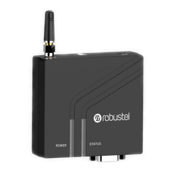
5. GSM MODEM PARTS The GSM Modem parts are identified below; Aidcall Part No. ZNC520 Power Supply & Adapters PSU Connector Antenna Data Cable (5m) Modem Wall Mounting Bracket IMPORTANT: the GSM Modem does not contain a standby battery so remote diagnostics cannot be performed during a mains failure. -
Page 7: Gsm Modem Installation
6. GSM MODEM INSTALLATION The GSM Modem requires connection to the mains supply via a local un-switched 13A mains socket and a hardwired data connection to the Touchsafe Pro Master Panel. The Modem is suitable for indoor locations only – NEVER fit externally. - Page 8 Plug shrouded 9 pin “D” plug end of the Data Cable into the Modem and finger-tighten the jack screws. Route the Data Cable to the Touchsafe Pro Master Panel and plug the un-shrouded 9 pin “D” plug into COM1 (as shown below). The 5m Data Cable can be cut-down in length but DO NOT extend any longer.
-
Page 9: Inserting/Removing The Sim Card
7. INSERTING/REMOVING THE SIM CARD Insert the SIM Card (Aidcall Part No. W01825) into the Modem SIM socket as shown below... Top Face of the Modem INSERT SIM CARD Make sure the Modem power supply is disconnected. To insert SIM card, press the card with finger until you hear a click. -
Page 10: Touchsafe Pro Panel Setup
“AidcallIP.txt”. This file can be set to the required IP address e.g. 10.23.10.45. If this is done, checking the “Connect To Aidcall” checkbox will result in an IP connection being made to the address contained within the file. - Page 11 8. TOUCHSAFE PRO PANEL SETUP Text Error To Caller: If the panel cannot make a connection to the remote IP address, an SMS can be sent to the mobile number entered in the “Accept Call From” field. This will indicate the IP address that it is attempting to connect to, the signal strength and the stage of the connection at which the failure occurred, e.g.
-
Page 12: Pc Software Installation
9. PC SOFTWARE INSTALLATION The Windows software installer will consist of 2 files; Setup.exe TSP GSM Modem.msi Double Click on the Setup.exe file and follow the install process… Click Next… This will install the application into the Program Files directory as shown above. The example here shows that it will be installed for all users. - Page 13 9. PC SOFTWARE INSTALLATION You may be prompted to allow the install of the application… Click Yes. The installer will run and upon completion the following message will be displayed; Click Close. A shortcut will have been created on the desktop of your PC. The shortcut is called “TSP GSM Modem”...
-
Page 14: Running The Pc Software
Double Click on the shortcut to run the software, the following application will appear… Note: the remote Touchsafe Pro panel must be configured to allow the connection and the connection process must be started by either pressing the “Connect” button at the remote panel or by dialling into the panel from a mobile phone. -
Page 15: Request General Information
11. REQUEST GENERAL INFORMATION Press the “Request General Information” button to display information relating to the general settings of the panel such as Date, Time, Network ID, Preamble and software versions of the panel; Note: this information can be saved at any time for future reference. By default the data will be saved to C:\Temp\Site Name. -
Page 16: Request Log List
12. REQUEST LOG LIST Press the “Request Log List” button to display a list of the available log files. The data may take a while to arrive if it is a large file and the “Please Wait Collecting Data…” message will be shown. Individual files can then be selected from the drop down box and that file can be requested by pressing the “Request Log File”... -
Page 17: Request Atx List
13. REQUEST ATX LIST OG FILES Press the “Request ATX List” button to display a list of all ATX’s on the site. An individual ATX file can then be selected from the drop down box and that file can be requested by pressing the “Request ATX”... - Page 18 13. REQUEST ATX LIST Once the required parameters have been entered, they can be transmitted to the panel. A confirmation prompt will be displayed; If the data is sent to the main panel, it will be distributed to the other panels on the system. This means that once this new Call Point has arrived on site it can be activated on the system.
-
Page 19: Request Night Mode Settings
14. REQUEST NIGHT MODE SETTINGS Press the “Request Night Mode” button to display all Night Mode settings on the site; 15. REQUEST TELECARE LIST Press the “Request Telecare List” button to display a list of all Telecare devices on the site. An individual Telecare file can then be selected from the drop down box and that file can be requested by pressing the “Request Telecare... -
Page 20: Request Common Call List
16. REQUEST COMMON CALL LIST Press the “Request Common Call List” button to display a list of Common Calls setup on the site. An individual Common Call file can then be selected from the drop down box and that file can be requested by pressing the “Request Common Call File”... -
Page 21: Request Paging Information
18. REQUEST PAGING INFORMATION Press the “Request Paging Information” button to display a list of all Paging Files on the site. An individual Paging File can then be selected from the drop down box and that file can be requested by pressing the “Request Pager File”... -
Page 22: Request Panel Information
20. REQUEST PANEL INFORMATION Press the “Request Panel Information” button to display a list of all files associated with the panel configuration on the site. An individual Panel File can then be selected from the drop down box and that file can be requested by pressing the “Request Panel File”... -
Page 23: Specification
22. SPECIFICATION Modem Manufacturer Robustel Model No. M1000 MP Standards LTE Cat 1 Serial Port Female 9 Pin D - RS232 115,200 Baud Female Mini USB 2.0 Power Indicator Green LED Status Indicator Green LED SIM Interface 3V/1V8 SIM Power Connector 2 Pin 3.5mm Male Terminal Block Input Voltage 6 to 36V DC...
Need help?
Do you have a question about the Touchsafe Pro and is the answer not in the manual?
Questions and answers