Table of Contents
Advertisement
Quick Links
Advertisement
Table of Contents

Subscribe to Our Youtube Channel
Related Manuals for Projecta SC300D


Summary of Contents for Projecta SC300D
- Page 1 SOLAR CHARGE REMOTE P/No. SC300D...
-
Page 2: General Information
GENERAL SAFETY INFORMATION • Read all instructions and cautions in the manual before starting the installation. • Keep the SC300D away from rain, exposure, severe dust, vibrations, corrosive gas and intense electromagnetic interference. • Do not allow water to enter remote meter. -
Page 3: Surface Mount Installation
INSTALLATION Frame Mount Dimensions 36.1 (4.49) (1.42) Mechanical Parameter 32.7 (1.29) parameter Overall 114 x 114 x 32.7mm dimension 4.49 x 4.49 x 1.29 inches 88.6 (3.49) (4.49) Mounting 88.6x 88.6mm dimension 3.49 x 3.49 inches Terminal Surface Mount Installation Step1: Locate and drill screw holes based on the frame mounting dimension of the base, and erect the plastic... -
Page 4: Product Overview
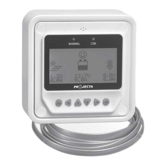
PRODUCT OVERVIEW Front View Failure indicator Alarm Communication indicator Display screen Buttons Rear View RS485 communication and power interface RS485... -
Page 5: Failure Indicator
Failure indicator Failure indicator flashes in case of failure of the connection devices. For failure information please check the Controller Manual. Alarm Fault audible alarm, could be activated or deactivated. Communication indicator Indicate communication status when MT50 is connected with the controller. Display screen Man-machine interaction operation interface. -
Page 6: Operation
Load current icon The load current icon is displayed if there is discharge current. Load status icon Load ON, Load OFF. OPERATION Buttons The buttons are respectively (from left to right) “ESC”, “Left”, “Up”, “Down”, “Right” and “OK “buttons, the operation is described in the schematic operation diagram below: Schematic operation diagram Browse... -
Page 7: Real-Time Monitoring
Real-time monitoring There are 14 pages under real-time monitoring. Please check it as below: LSxxxxB Month-Day-Year H:M:S Char. Energy DisCh. Energy Day: 0000.00 kWh Day: 0000.00 kWh Mon: 0000.00 kWh Mon: 0000.00 kWh Total: 0000.00 kWh Total: 0000.00 kWh Battery Battery Battery Vol: 000.0V... -
Page 8: Device Information
Operational tips: buttons are respectively used to turn the browse page upward and downward, while buttons are respectively used to turn the interfaces left and right. Device information The product model, parameters and SN code of the controllers are displayed below: Product type Product type Rate. -
Page 9: Control Parameters
Control parameter Browse and modification operations are conducted over the control parameters of solar charge controller. See the scope of parameter modification in control parameters table, and the page of control parameters in the diagram below: Batt. type Temp Comp.Coeff. Over Volt. - Page 10 Battery voltage parameters (Parameters is in 12V system at 25 C , please use X 2 in 24V.) Control voltage parameters Battery charging setting Sealed Flooded User Over voltage disconnect voltage 16.0V 16.0V 16.0V 9–17V Charging limit voltage 15.0V 15.0V 15.0V 9–17V Over voltage reconnect voltage...
-
Page 11: Load Setting
Load setting The page of load setting could be used to set the four load working modes of the connection solar controller (Manual, Light on/off, Light on+timer, Time control). Manual Control Light on/off Manual Control Default: ON/OFF Light on+Timer Time Control Manual Control Light: on/off Light on/off... -
Page 12: Time Control
3. Light ON+ timer The real working time Working time 1 (T1) Load working period after light control turns of T2 depends on the ON load Night time, and the Working time 2 (T2) Load working period before light control length of T1, T2. -
Page 13: Device Parameter
Device parameter The software version information of solar charge controller could be checked via the page of device parameters, and device data like device ID, device LCD backlight time and device clock could be checked and modified. The page of device parameter in the diagram below: Device Parameter Device Parameter... -
Page 14: Failure Information
harging mode Notes Vol.Compen. Voltage compensation: Voltage control charging (default) By setting the charge and discharge SOC target values for battery charge and discharge control Factory reset The default parameter values of solar charge controller could be restored via the Factory reset page, which means the “Control parameter”, “Load setting”, “Charge mode”... - Page 15 Meter parameter Parameters Default Range Remark Sw-Pages 0–120S The automatic switchover for real-time monitoring page BKlight 0–999S LCD backlight time AudiAlam ON/OFF Turn ON Electrical Electrical parameter Backlight and acoustic alarm ON<65mA Self-consumption Backlight ON<23mA Backlight OFF<15mA Mechanical Mechanical parameter Faceplate dimensions 98×98 mm / 3.86×3.86 inches Frame dimensions...
-
Page 16: Warranty Statement
WARRANTY STATEMENT Applicable only to product sold in Australia Brown & Watson International Pty Ltd of 1500 Ferntree Gully Road, Knoxfield, Vic., telephone (03) 9730 6000, fax (03) 9730 6050, warrants that all products described in its current catalogue (save and except for all bulbs and lenses whether made of glass or some other substance) will under normal use and service be free of failures in material and workmanship for a period of one (1) year (unless this period has been extended as indicated elsewhere) from the date of the original purchase by the consumer as marked...
Need help?
Do you have a question about the SC300D and is the answer not in the manual?
Questions and answers