
Related Manuals for Projecta IP3000


Summary of Contents for Projecta IP3000
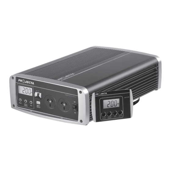
- Page 1 INTELLI-WAVE 2000W/3000W PURE SINE WAVE INVERTER P/No. IP2000, IP2000-24, IP3000, IP3000-24V2...
-
Page 2: Important Safety Information
IMPORTANT SAFETY INFORMATION Please read this manual thoroughly before use and store in a safe place for future reference. WARNINGS • For indoor use out of weather only. • For use with negatively earthed vehicles & systems only. • Internally bonded for safety, battery DC negative to case & AC socket earth. •... - Page 3 FEATURES PURE SINE WAVE OUTPUT There are two different types of inverters, modified sine wave and pure sine wave. The difference between the two is how closely the output replicates mains power. Logically it follows that the process used in a pure sine wave inverter is more complex than a modified sine wave inverter and subsequently more expensive.
-
Page 4: Remote Control Display
REMOTE CONTROL DISPLAY Control and monitor the inverter’s performance from a remote control display allowing the inverter to be mounted flush or surface mounted out of sight. Ideal for use in caravans, motor homes and boats. BI-COLOUR L.E.D DISPLAY THERMOSTATICALLY CONTROLLED 3 SPEED COOLING FAN PROTECTION •... - Page 5 SPECIFICATION (CONTINUED) P/No. IP3000 IP3000-24V2 Input 12VDC Battery/Vehicle 24VDC Battery/Vehicle (9.75–15.5VDC) (19.5–31.0VDC) Input Current (Max DC Amps) 300A 150A No Load Current Draw 650mA 350mA Remote Standby Current Draw ECO Mode Current Draw 10mA ECO Mode Sleep <1W ECO Mode Wake >6W...
-
Page 6: Product Overview
PRODUCT OVERVIEW FRONT VIEW LCD Screen RCD Safety AC Output On/Off Sockets Switch Switch 2000W Pure Sine Wave VOLTS WATTS AC OUTPUT AC OUTPUT 2000W Pure Sine Wave LOAD% Display Selection Mounting Buttons Holes VOLTS WATTS AC OUTPUT AC OUTPUT LOAD% REAR VIEW MAINS AC... -
Page 7: Mounting Instructions
10cm clearance from the end plates to provide adequate ventilation for the cooling fan. 6.5mm mounting holes Part No. Inverter Dimensions Length Width Height IP2000 & IP2000-24 478mm 250mm 105mm IP3000 & IP3000-24V2 535mm 250mm 105mm... - Page 8 2. Install a circuit breaker or high current fuse and fuse holder in the positive line as close to the battery as possible. The following fuse & fuse holder is available from Projecta IP2000: P/No. IFB-250 (250A fuse and holder) 12 Volt IP3000: P/No.
- Page 9 AC output power can be wired directly from the OUTPUT terminals of the inverter allowing connection to external GPO’s in addition to the outputs located on the front of the IP2000/IP3000 unit. 1. Ensure the inverter is turned off and disconnected from DC & AC mains power.
- Page 10 WIRING AC MAINS POWER TO THE INVERTER 1. Ensure the inverter is turned off and disconnected from DC power, also ensure AC mains wiring to be connected to the inverter is isolated and safe to work with. 2. To gain access to the INPUT terminals remove the cover located at the back of the unit using a phillips head screw driver.
- Page 11 REMOTE CONTROL DISPLAY To install the remote control, insert the data plug into the data socket at the rear of the inverter. To operate the inverter using the remote, the inverter On/Off switch must be turned to ON. The remote is equipped with an LCD screen identical to the inverter, as well a bi-colour status L.E.D and audible alarm.
-
Page 12: Surface Mount
MOUNTING REMOTE CONTROL FLUSH MOUNT • Cut a 93mm x 70mm hole into the desired mounting surface to suit the supplied mounting plate. • Position the mounting plate into the hole with the side labelled ‘FLUSH MOUNT’ facing outwards and screw the supplied screws into the mounting surface as per the below illustration. -
Page 13: Flush Mount
REMOVING REMOTE CONTROL FLUSH MOUNT 1. Pull the remote control sideways and firmly lift 2. The remote will click out of place SURFACE MOUNT 1. Holding the remote on either side, push upwards. 2. Squeeze the sides together to lift away. - Page 14 UNDERSTANDING YOUR INVERTER These inverters are equipped with an audible alarm and a multi-function LCD screen with selection buttons allowing you to monitor the inverter’s performance. During normal operation, the LCD screen will default to the VOLTS display (input battery voltage).
-
Page 15: Eco Mode Settings
OPERATING INSTRUCTIONS To operate the inverter turn the inverters On/Off switch to ON. The inverter will beep momentarily while it carries out a brief self-analysis before supplying power to the AC socket. To turn off, turn the inverter On/Off switch to OFF. Note: Ensure the RCD Switch is down, the red indicator will be showing. - Page 16 FAULTS & ERRORS Problem Possible Cause Solution Low battery voltage Input battery voltage is a) Recharge battery below 10.5V (12V), 21V (24V) b) Battery may be too small. Refer to pg 16 for recommended battery sizes c) Check cable connections and that cable sizes are sufficient (see pg 6) Low battery Shutdown a) The input battery voltage...
- Page 17 (Amps) drawn under normal use. The following table shows the maximum combined AC Watts or AC Amps which can be run by the inverter. P/No. IP2000 IP3000 AC Combined maximum load (Watts) 2000W 3000W AC Combined maximum load (Amps) 8.3A...
-
Page 18: Troubleshooting (Faq)
TROUBLESHOOTING/FAQ: Q. Why does the inverter turn itself off? A. If the inverter’s audible alarm sounds and a fault L.E.D illuminates, this indicates that there is a fault or error, and the inverter may turn off. Most commonly this would be caused by an appliance that is drawing too much power (overloading), low battery voltage or voltage drop due to insufficient size cables or poor connections (refer to ‘Faults &... - Page 19 Q. Why does it damage the inverter if the battery leads are reverse-connected? A. Your inverter uses sophisticated electronics to convert DC battery power to AC mains power. If you accidentally connect the inverter to the battery incorrectly (reverse polarity) a large current will be drawn by the inverter which will blow the protection fuse.
-
Page 20: Warranty Statement
WARRANTY STATEMENT Applicable only to product sold in Australia Brown & Watson International Pty Ltd of 1500 Ferntree Gully Road, Knoxfield, Vic., telephone (03) 9730 6000, fax (03) 9730 6050, warrants that all products described in its current catalogue (save and except for all bulbs and lenses whether made of glass or some other substance) will under normal use and service be free of failures in material and workmanship for a period of two (2) year (unless this period has been extended as indicated elsewhere) from the date of the original purchase by the consumer as marked...
Need help?
Do you have a question about the IP3000 and is the answer not in the manual?
Questions and answers