Table of Contents
Advertisement
Advertisement
Table of Contents

Subscribe to Our Youtube Channel
Related Manuals for Projecta IP150


Summary of Contents for Projecta IP150
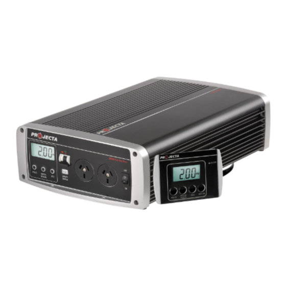
- Page 1 INTELLI-WAVE INVERTER 12 VOLT, PURE SINE WAVE P/No.s IP150, IP300, IP600, IP1000...
-
Page 2: Important Safety Information
• Batteries can be dangerous; follow all battery manufacturer’s instructions and warnings. • Never operate the inverter without the DC negative input connected direct to the battery and never install a fuse, circuit breaker or battery switch in the negative supply line (IP150 excepted). - Page 3 FULLY ISOLATED DESIGN Safety is paramount around 240V and in particular with inverters which is why Projecta fully electrically isolates the DC (and therefore battery posts, vehicle chassis, etc) from the 240V AC circuit.
-
Page 4: Specifications
SPECIFICATIONS P/No. IP150 IP300 IP600 IP1000 Input 12VDC Battery/Vehicle (9.75–15.5VDC) Input Current (Max DC Amps) 100A No Load Current Draw 500mA 500mA 650mA 1200mA Remote Standby Current Draw – – Output 240VAC 50Hz Continuous Power (Watts) 150W 300W 600W 1000W... -
Page 5: Product Overview
PRODUCT OVERVIEW IP150 FRONT VIEW REAR VIEW AC Output Socket Bi-Colour Chassis Status L.E.D Ground 150W Pure Sine Wave STATUS CHASSIS 12V DC AC OUTPUT INPUT Cigarette Plug Mounting Flange On/Off Switch DC Input Lead IP300 FRONT VIEW REAR VIEW... -
Page 6: Connecting The Inverter
CONNECTING THE INVERTER IP150 The IP150 is fitted with a lead and cigarette plug. Insert the plug into the vehicle’s 12V accessory socket and turn the inverter on. You may need to turn the vehicle’s ignition to ‘accessory’ to supply power to the inverter. -
Page 7: Mounting Instructions
10cm clearance from the end plates to provide adequate ventilation for the cooling fan. 3.5mm mounting hole Part No. Inverter Dimensions Length Width Height IP150 232mm 108mm 63mm IP300 252mm 108mm 63mm... - Page 8 UNDERSTANDING YOUR INVERTER A) IP150 & IP300 These inverters are equipped with a bi-colour status L.E.D and audible alarm. During normal operation, the L.E.D will illuminate solid green. In the event of a fault or error, the alarm will sound and the L.E.D will illuminate various signals.
- Page 9 REMOTE CONTROL DISPLAY (IP600 & IP1000 ONLY) To install the remote control, insert the data plug into the data socket at the rear of the inverter. To operate the inverter using the remote, the inverter On/Off switch must be turned to ON. The remote is equipped with an LCD screen identical to the inverter, as well a bi-colour status L.E.D and audible alarm.
-
Page 10: Flush Mount
MOUNTING REMOTE CONTROL FLUSH MOUNT • Cut a 93mm x 70mm hole into the desired mounting surface to suit the supplied mounting plate. • Position the mounting plate into the hole with the side labelled ‘FLUSH MOUNT’ facing outwards and screw the supplied screws into the mounting surface as per the below illustration. - Page 11 REMOVING REMOTE CONTROL FLUSH MOUNT 1. Pull the remote control sideways and firmly lift 2. The remote will click out of place SURFACE MOUNT 1. Holding the remote on either side, push upwards. 2. Squeeze the sides together to lift away.
- Page 12 FAULTS & ERRORS Problem Possible Cause Solution Low battery voltage Input battery voltage a) Recharge battery is below 10.5V b) Battery may be too small. Refer to pg 13 for recommended battery sizes c) Check cable connections and that cable sizes are sufficient (see pg 6) a) Recharge battery immediately.
- Page 13 All appliances have a rating plate that shows the amount of power (Watts) used or the current (Amps) drawn under normal use. The following table shows the maximum combined AC Watts or AC Amps which can be run by the inverter. P/No. IP150 IP300 IP600 IP1000 AC Combined maximum load (Watts)
-
Page 14: Troubleshooting (Faq)
TROUBLESHOOTING/FAQ: Q. Why does the inverter turn itself off? A. If the inverter’s audible alarm sounds and a fault L.E.D illuminates, this indicates that there is a fault or error, and the inverter may turn off. Most commonly this would be caused by an appliance that is drawing too much power (overloading), low battery voltage or voltage drop due to insufficient size cables or poor connections (refer to ‘Faults &... - Page 15 Q. Why does it damage the inverter if the battery leads are reverse-connected? A. Your inverter uses sophisticated electronics to convert DC battery power to AC mains power. If you accidentally connect the inverter to the battery incorrectly (reverse polarity) a large current will be drawn by the inverter which will blow the protection fuse.
-
Page 16: Warranty Statement
WARRANTY STATEMENT Applicable only to product sold in Australia Brown & Watson International Pty Ltd of 1500 Ferntree Gully Road, Knoxfield, Vic., telephone (03) 9730 6000, fax (03) 9730 6050, warrants that all products described in its current catalogue (save and except for all bulbs and lenses whether made of glass or some other substance) will under normal use and service be free of failures in material and workmanship for a period of one (1) year (unless this period has been extended as indicated elsewhere) from the date of the original purchase by the consumer as marked on...
Need help?
Do you have a question about the IP150 and is the answer not in the manual?
Questions and answers