Table of Contents
Advertisement
Quick Links
Advertisement
Table of Contents

Subscribe to Our Youtube Channel
Related Manuals for Seaga Quick Break Combo QB4000


Summary of Contents for Seaga Quick Break Combo QB4000
- Page 1 QB4000 vers 1.0 2.2024...
- Page 2 Once you have your vendor located, we suggest that you keep this manual for future reference, or you can view this manual online at www.seaga.com. Should any problems occur, refer to the section entitled “TROUBLESHOOTING”. It is designed to help you quickly identify a problem and correct it.
-
Page 3: Table Of Contents
Table of Contents Preliminary Information CAUTIONS Initial Setup Removing Snack Trays Adjusting Coils Replacing Snack Motors Loading Product Lanes Customer Interface Setting Up and Loading the Payment Systems Coin Changer Loading Changer Coin Retrieval Clearing Coin Jams Removal of Coin Changer Bill Validator Bill Validator Capacity Bill Retrieval... -
Page 4: Preliminary Information
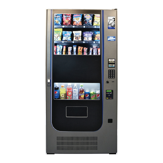
Preliminary Information Figure 1 – The QB4000 Vending Machine Main Unit - VMC Aux. Display Window Snack Display LED Display Window Display Bill Acceptor Keypad Main Door Coin Insert Slot Handle and Lock Beverage Display Window Coin Return Button Credit Card Snack &... - Page 5 Machine Description Main Unit Model Number QB4000 Height (in) 73.5 Width (in) Depth (in) 34.5 Volts (V) Frequency (Hz) Watts (W) Current (A) Refrigerant R290 Refrigerant Charge (oz) 1.59 Figure 2 - Interior of machine and controls Display Snack Trays LED Display Bill Validator Insulated Door...
-
Page 6: Cautions
Power Requirements The wall receptacle used for your vendor must be properly polarized, grounded and of the correct voltage. Operating the QB4000 system from a source of low voltage will VOID YOUR WARRANTY. Each QB4000 system should have its own 15 Amp electrical circuit that is protected by a circuit breaker or fuse conforming to local power safety regulations. - Page 7 CAUTION! Different countries may have different power arrangements. Ensure that the machine is properly grounded before operating. CAUTION! If the power cord is damaged, it must be replaced by the manufacturer, authorized service agent or a similarly qualified person to avoid electrical hazards. ATTENTION! This dispensing machine is very heavy.
-
Page 8: Initial Setup
Initial Setup Moving the Vending System Your QB4000 system should never be moved with product or coins loaded, it should be completely empty, and any moving parts must be secured. The system can be located as close as 2 inches to the back wall but requires 6 inches clearance on either side for the doors to open properly while you service the machine. - Page 9 Tool Kit Suggested tools for your tool kit are: Phillips screwdrivers Adjustable pliers Needle Nose pliers Socket Set including 5.5 mm, 7 mm and 10 mm Leg Levelers Leg Levelers have been provided in your parts pack as it is essential for proper operation to have a level vending machine.
- Page 10 Theory of Operation for Snack & Entree Trays When a snack vends, power is sent to the motor (that drives the coil) and it turns until the motor hub is back to the internal “home switch” then it stops and the vend is considered to be complete.
- Page 11 Products Make sure your products are appropriate for the column and coil you are placing them in. Do not force products that are too wide into a narrow tray or too tight coil as this will cause vend problems for your customers.
-
Page 12: Removing Snack Trays
Removing Snack Trays It is sometimes necessary to replace a snack tray or you may find it easier to work on certain elements of a tray if it is removed from the vending system cabinet. Figure 5 – Tray Harnesses Tray 110 Harness Tray 120 Harness Tray 130 Harness... -
Page 13: Adjusting Coils
Figure 6 – Remove the tray Tray 130 Harness Lift tray free Adjusting Coils If you are required by a location to vend a product of a non-standard size, you may need to order a different coil and install it. Replacing a coil is easier with the tray removed, as described in the last section. To replace a coil: 1. -
Page 14: Replacing Snack Motors
If you are experiencing vending issues with certain products, you may need to adjust the coil rotation to better provide the momentum to push the snack off the tray and into the delivery area. To adjust the coil rotation: 1. Squeeze the two tabs on the back of the coil driver and pull the coil driver and coil toward the front of the tray to remove it. -
Page 15: Loading Product Lanes
Theory of Operation of Beverage Vending The beverage section uses two (2) Drop Sensors (vibration sensors) to detect the product drop. In normal operation, the auger will rotate counterclockwise to drop a product onto the delivery chute. Upon detection of the product drop by these sensors, the motor (driving the auger) will stop and the vend is considered complete. - Page 16 Unlike the snack section of the vending system, the products that will vend are not viewable by your customers when they are positioned in the vertical drop columns. To provide a live display, a product display shelf has been provided. Take care to use packaging that is in perfect condition and products that are still within their expiration date to present the best possible retail store front to your potential customers.
- Page 17 Display Formats When in Sales Mode Display Reads Normal Operation, no credit available Good Morning, Good Afternoon & Good Evening Normal Operation, some credit available $00.01 – 99.99 After Pressing a selection, if there is no credit or the credit is less than the selection’s price, the price of the selection is displayed for a few seconds before Price $00.01 –...
-
Page 18: Setting Up And Loading The Payment Systems
Setting Up and Loading the Payment Systems Coin Changer The Coin Changer receives and returns change to customers. The Coin Changer will accept Dollar Coins, Quarters, Dimes, and Nickels. Once the coin tubes reach the required inventory level, all other coins will be routed into the coin overflow tray. -
Page 19: Clearing Coin Jams
Clearing Coin Jams 1. Unplug the machine from the power source 2. Unlock and open the Front Door 3. Open the Acceptor Gate Assembly by pulling forward on the Coin Funnel 4. Check for coin jams in this area. Note: the ramp in this area should also be cleaned on a regular basis to insure trouble-free operation. -
Page 20: Removal Of Coin Changer
Removal of Coin Changer To Remove the Coin Changer: a. Disconnect the power to the machine – this is very important to avoid damaging not only the coin changer but your VMC. Failure to disconnect power before performing this operation will void your warranty. b. -
Page 21: Bill Validator
c. Lift up on the white lever on the top left side of the coin mechanism d. Tilt the Discriminator assembly forward and lift off main housing. Note: the discriminator will still be at- tached by a cable. e. Loosen the three (3) Mounting Screws f. -
Page 22: Removing Bill Validator
Figure 13 – Bill Validator Bill Collection Box (4) Mounting Nuts Lower Housing REMOVING BILL VALIDATOR From time to time it may be necessary to remove the Bill Validator for cleaning and clearing jams. a.Disconnect the power to the machine – this is very important to avoid damaging not only the bill validator but your VMC. -
Page 23: Clearing Bill Jams
Wire Harness Four (4) Mounting Nuts f. Remove Bill Validator Clearing Bill Jams It is possible that a torn or damaged bill can jam within the Bill Validator, putting it out of service. 1. To Clear a Jam. a. Remove Bill Collection Box as instructed in Bill Retrieval and inspect for a jammed bill b. - Page 24 d. Inspect and remove jammed bill. e. Replace lower unit to resume normal operation. QB4000 vers 1.0 2.2024...
-
Page 25: Programming
PROGRAMMING Enter Service Mode by pressing the MENUS Button on the VMC Circuit board. (Fig. 14) Figure 14 – VMC and Menus Button Menus Button SERVICE MODE NAVIGATION Use the 0 through 9 keys to access the various menus and sub-menus. Use the “*”... - Page 26 SERVICE MODE 1. PRICE PROGRAM Price Program is used to set the prices for All Items, by Row or by individual Selection. Save time and set All Items to the most common price, going back to Row or Selection for different prices as required. The value for Coupons accepted by pre-programmed validators and Tokens accepted by pre-programmed coin changers as well as Combo pricing are also set in this menu.
- Page 27 COUPON IMPORTANT: This option requires a programmed validator. Up to five different coupon values can be set. In sales mode, once a coupon is accepted, no further coupons will be accepted until a successful vend has been made. If no value is set, coupons will be shown as free vends. If using both coupons and tokens, there are only five selection combinations available. For example, if Coupon1 is set for “All Items”, Token1 is also set for “All Items”.
- Page 28 COUPON BY SELECTION 1. Press Service Mode Button Press 1 for Price Program Press 4 for Coupons 4. Press 1 for Coupon1 (or corresponding number for additional coupons, up to Coupon5) Press 1 for All Items 6. Press 1 to toggle to Off Press # to save changes Press * to exit to previous menu Press 3 to enter a Selection Use the number keys to enter a Selection number 11. Press 1 to toggle Item On/Off Press # to save the setting...
- Page 29 TOKEN BY ROW 1. Press Service Mode Button Press 1 for Price Program Press 5 for Tokens 4. Press 1 for Token1 (or corresponding number for additional coupons, up to Token5) Press 1 for All Items 6. Press 1 to toggle to Off Press # to save changes Press * to exit to previous menu Press 2 to enter a Row Number Use number keys to enter Row Number 11. Press 1 to toggle Row On/Off Press # to save changes...
- Page 30 COMBO Combos are a group of 2-5 selections that can be sold together for one price. For example, a price of $7.50 the customer will be able to purchase a bagged snack (110), a snack from the third tray (131) and a drink (142) which will all vend when the Combo Selection is used. If the customer purchased these items separately it would cost them more. Combos are used to encourage higher vend amounts through discounted pricing. Up to five Combos may be set up. Combos are product specific so when you list the Combos for a machine you will want to list the specific products. We recommend that you show the savings with a Combo versus buying the selections individually via some sort of signage or electronic display.
- Page 31 CALORIES CALORIES ALL ITEMS 1. Press Service Mode Button Press 1 for Price Program Press 7 for Calories Press 1 All Items Using number keys enter Calorie Value Press # to save changes Press * to exit to previous menu CALORIES BY ROW 1.
- Page 32 Press 1 to view Historical Count Press 2 to view Historical Cash Press 3 to Reset Count Press 4 to Reset Cash Press 5 to view Historical Card Press 6 to Reset Card Press 7 to Clear Press * to exit to previous menu ROW (2) 1.
- Page 33 4. CONFIGURATION The following sub-menus are included in the Configuration Menu: • Date/Time • Selection – Type • Health Safety • Auto Reinstate • Language • StS • All Items – Type • StS Custom • Row – Type • Advanced Config* DATE/TIME 1. Press Service Mode Button 2. Press 4 for Configuration Press 1 for Date/Time 4. Press 1 to change Date (MM/DD/YY) Press # to Edit Date Use number keys to enter Date in format shown...
- Page 34 LANGUAGE 1. Press Service Mode Button 2. Press 4 for Configuration Press 3 for Language Press 3 to toggle choices Press # to Save changes Press * to exit to previous menu ALL ITEMS: TYPE 1. Press Service Mode Button 2. Press 4 for Configuration Press 4 for All Items: Type* Press 1 to Edit/Toggle between Snack, Can or SO Switch Press # to Save changes Press * to exit to previous menu...
- Page 35 Press # to Save changes Press * to exit to previous menu SPACE TO SALES (StS) This feature is not applicable in this model and must be set to OFF. 1. Press Service Mode Button 2. Press 4 for Configuration 3. Press 8 for Space to Sales (StS) Press 8 to Edit 5. Press 8 to toggle through options to StS Off Press # to Save changes Press * to exit to previous menu...
- Page 36 MOTOR TYPE Note: Must be set to 3-Wire for this model. 1. Press Service Mode Button 2. Press 4 for Configuration 3. Press 0 for Advanced Config 4. Use number keys to enter Password (2314) Press 3 for Motor Type menu 6. Press 3 to toggle to 3-Wire (other options: Solenoid, 2-Wire, 2-Wire 1ms or 3-Wire Slow) Press # to save changes Press * to exit to previous menu TEMP Note: Must be set to COLD. 1.
- Page 37 FORCED VEND Forces the customer to complete a purchase once they have made payment in any form. NOTE: If a customer chooses a Forced Vend selection and the motor fails, the customer will be allowed to escrow the credit. 1. Press Service Mode Button Press 5 for Options Menu Press 1 for Forced Vend Menu Press 1 to toggle between ON and OFF...
- Page 38 FREE VEND Sets the WHOLE MACHINE to Free Vend. Every product is at no cost, no money is accepted by the machine and the display reads “FREE ON US”. 1. Press Service Mode Button Press 5 for Options Menu Press 4 for Free Vend Menu Press 4 to toggle between ON and OFF Press # to save changes Press * to exit to previous menu...
- Page 39 specific machine refrigeration modes. Ambient snack machines without a refrigeration system will display 43 °F. These temperatures may be adjusted; however, it is not advised without direction by an authorized technician. The optimal temperatures have been set according to NAMA specifications for optimal product safety. Before making any adjustment see Temp and Health Safety section. 1. Press Service Mode Button Press 5 for Options Menu Press 8 for Set Point Press 8 to edit the temperature Set Point 5. Continue pressing 8 until the desired temperature is shown on the display (0-250)
- Page 40 Press 1 for Discount Press 7 for All Items Use keypad to enter discount price for All Items Press # to save changes Press * to exit to previous menu 9. Press 1 for Interval1 (up to 4 Intervals may be chosen) Press 1 for All Items Press 1 to toggle ON/OFF Press # to save changes Press * to exit to previous menu Press 4 for Day menu...
- Page 41 Press 6 for Advanced Menu 3. Use number keys to enter Password (2314) Press 1 for Discount Press 8 for Row Use keypad to enter Row number and discount price for the entire row Press # to save changes Press * to exit to previous menu 9. Press 1 for Interval1 (up to 4 Intervals may be chosen) Press 2 for Row Use number keys to enter row number Press 1 to toggle ON/OFF...
- Page 42 DISCOUNT BY SELECTION Note: Make sure the All Items setting in the Discount Interval menu is set to OFF. See Discount All Items 1. Press Service Mode Button Press 6 for Advanced Menu 3. Use number keys to enter Password (2314) Press 1 for Discount Press 9 for Selection Use keypad to enter Selection number and discount price Press # to save changes Press * to exit to previous menu...
- Page 43 42. Use number keys to enter Stop Time in 12-hr time format (HH:MM:SS) AM/PM Press # to save changes Press * to exit to previous menu EXACT CHANGE Sets the coin tube value that will trigger the display to show “Please Use Exact Change” message. For example, if Exact Change is set to $5.00, the message will display when the total of coins in the tube, as counted by the VMC, is at or below $5.00 total.
- Page 44 Use number keys to enter value Press # to save changes Press * to exit to previous menu MAX CHANGE This option prevents change from being returned to the customer until the amount of credit has been reduced to a value less than or equal to the programmed maximum change limit. 1.
- Page 45 Press 2 for Monday menu Press 2 to toggle Monday ON/OFF Press # to save changes Use numbers 3-8 to complete the other days of the week using steps 14 thru 16. Press * to return to previous menu Press 5 for Start Time menu Press 5 again or press # Press # to Edit 22. Use number keys to enter Start Time in 12-hr time format (HH:MM:SS) AM/PM...
- Page 46 Use numbers 3-8 to complete the other days of the week using steps 15 thru 17. Press * to return to previous menu Press 5 for Start Time menu Press 5 again or press # Press # to Edit 23. Use number keys to enter Start Time in 12-hr time format (HH:MM:SS) AM/PM Press # to save changes Press * to return to previous menu Press 6 for Stop Time menu...
- Page 47 Press 5 again or press # Press # to Edit 23. Use number keys to enter Start Time in 12-hr time format (HH:MM:SS) AM/PM Press # to save changes Press * to return to previous menu Press 6 for Stop Time menu Press 6 again or press # Press # to Edit 29. Use number keys to enter Stop Time in 12-hr time format (HH:MM:SS) AM/PM Press # to save changes Press * to return to previous menu Press 8 for Lighting menu...
- Page 48 Press * exit to previous menu Press 6 for Stop Time menu Press 6 again or press # Press # to edit 26. Use number keys to enter Stop Time in 12-hr time format (HH:MM:SS) AM/PM Press # to save changes Press * to exit to previous menu 29. Press 7 to enter Storage Temp (default is 62°F) 30. Press 7 to edit Storage Temp (39°F to 62°F) Press # to save changes Press * to exit to previous menu Press 8 for Lighting menu Press 8 to toggle Lighting ON/OFF...
- Page 49 8. TEST VEND This function tests the motor on one specified selection. 1. Press Service Mode Button Press 8 for Selection motor test menu Use number keys to enter selection to test and wait Repeat for any other selections Press * to exit to previous menu 9. SELECTION: ALL This function tests all motors in sequence automatically.
-
Page 50: Menu Hierarchy
ON DOOR 1. Press Service Mode Button Press 0 for Test Modes Press 4 for On Door Press 4 to toggle SHOW ERRORS/OFF when door opens Press * to exit to previous menu MANUAL DEFROST Note: Do not use unless requested by trained personnel 1. - Page 51 4-0-1 Beep Enable 4-0-2 Optics Disables 4-0-3 Motor Type 4-0-4 Temp 4-0-5 Selection Style 5 – Options 5-1 Forced Vend 5-2 Bill Escrow 5-3 Multi-Vend 5-4 Free Vend 5-5 Fast Change 5-6 Optical Vend 5-7 POS Message 5-8 Set Point 5-9 Sensitivity Adjust 6 –...
-
Page 52: Error Code Messages
ERROR CODE MESSAGES VMC Errors Error Message Description Possible Solutions VMC Settings Reset VMC has been reset to factory If a software upgrade has just default. been performed, the VMC has been reset to default settings. Change your prices and other settings as required. - Page 53 Motor [Number] Jam A motor jam has been detected. Check motor and spiral for blockage. Motor [Number] Errors One or more motor errors have Test vend selection motor and been detected. review information on motor open, short, home switch and jam conditions.
- Page 54 Coin Mech Excess Esc The coin changer has reported Check changer escrow lever that a large number of coin position. escrow requests have occurred. Coin Mech Coin Jam The coin changer has reported Check changer coin path. See that a coin is jammed in the coin changer service manual.
-
Page 55: Refrigeration
REFRIGERATION Your beverages are kept cold by a high efficiency refrigeration system having two air circulation fans to chill the cans and bottles. The refrigeration unit can be easily accessed by opening the Front Door. Remove the single blue thumbscrew from the center floor of the refrigeration deck and remove the partition wall. Remove the two screws holding the handles in place Figure 20. The refrigeration deck is a modular system consisting of Compressor, Condenser, Condenser fan, Evaporator, Evaporator Fans, Accumulator or Dryer, and Temperature Sensor which communicates to the VMC. The temperature is pre-set at the factory for efficient and effective operation. - Page 56 Rotate both handles outward and pull them toward you to remove them. Remove the guide bolt in the center of the refrigeration deck (Figure 22). The deck can now be pulled out from the vendor. Please make sure you unplug wire harnesses prior to pulling all the way out. Do not tip the refrigeration deck more than 20° in any direction. Figure 22 –...
- Page 57 The refrigeration system is monitored and controlled by several key electrical components. The condenser fan, two evaporator fans, temperature sensor, VMC, and the start and overload components located on the side of the compressor. The line voltage from the outlet in the room is fed to the three fans, the condenser fan and the evaporator fans, and they run continuously as long as the machine is plugged into power coming from the wall.
-
Page 58: Troubleshooting
Troubleshooting SELECTION DISPLAYS SOLD OUT WHEN PRODUCT IS PRESENT Product is not loaded correctly. Ensure product is located to the front of the column and depresses sold out indicator. A jam caused an error and Lockout – Press menu button then 7 to reactivate all lanes. -
Page 59: Frequently Asked Questions
MACHINE WILL NOT COOL Press the “#” key on the keypad to get a temperature reading Verify that Temp Set is 43° F in Service Mode. Note: Setting the temperature too cold will put your evaporator at risk of freezing up. Verify that all fans are running Clean the condenser Remove your refrigeration deck and inspect for ice. - Page 60 2. Make sure all product loaded is installed in the correct selection. Load product according to the machine Plan-O-Gram. A change from the Plan-O-Gram may require new setup. See the Loading Beverage Lanes section of this manual and study the Product Groups and how to load them and accessories required (if any).
-
Page 61: Wiring Diagram
Wiring Diagram QB4000 vers 1.0 2.2024... - Page 62 Wiring Diagram QB4000 vers 1.0 2.2024...
-
Page 63: Exploded Views
EXPLODED VIEWS Machine Assembly QB4000 QB4000 vers 1.0 2.2024... - Page 64 Cabinet Assembly QB4000 QB4000 vers 1.0 2.2024...
- Page 65 Door Assembly QB4000 QB4000 vers 1.0 2.2024...
- Page 66 Inner Door Assembly QB4000 QB4000 vers 1.0 2.2024...
- Page 67 Tray 8 Selection QB4000 QB4000 vers 1.0 2.2024...
- Page 68 High Capacity Tray Assembly QB4000 QB4000 vers 1.0 2.2024...
- Page 69 Refrigeration Unit QB4000 (REI921) QB4000 vers 1.0 2.2024...
- Page 70 Transformer Panel QB4000 Parts List ITEM NO. PART NO. DESCRIPTION QTY. STI57042 BASE TRANSFORMER ELC946A FILTER FAI898 NYLOCK NUT ELI764 RELAY FAI922 NYLOCK NUT ELC478 TRANSFORMER FAI884 SCREW QB4000 vers 1.0 2.2024...
- Page 71 LIMITED WARRANTY Seaga warrants to the original purchaser that the equipment is free from defects in material and factory workmanship for a period of one (1) year from date of shipment. This warranty applies only if the equipment has been serviced and maintained in strict accordance with the instructions presented in the Operator’s Manual and no unauthorized service, repair, alteration or disassembly has been performed.
Need help?
Do you have a question about the Quick Break Combo QB4000 and is the answer not in the manual?
Questions and answers