
Related Manuals for Queclink TRACGV55WUM001


Summary of Contents for Queclink TRACGV55WUM001
- Page 1 GV55W User manual GV55W User Manual Mini Vehicle Tracking Devices With Internal Battery TRACGV55WUM001 Version: 1.00 TRACGV3SUM001 - 0 -...
- Page 2 TRACGV55WUM001 General Notes Queclink offers this information as a service to its customers, to support application and engineering efforts that use the products designed by Queclink. The information provided is based upon requirements specifically provided to Queclink by the customers. Queclink has not undertaken any independent search for additional relevant information, including any information that may be in the customer’s possession.
-
Page 3: Table Of Contents
3.5. Switch ON the Backup Battery ..................12 3.6. Power Connection ......................12 3.7. Ignition Detection ......................13 3.8. Digital Input ........................14 3.9. Digital Outputs........................14 3.10. Device Status LED ......................16 3.11. Motion Sensor Direction ....................18 TRACGV55WUM001 - 2 -... - Page 4 TABLE 6. ELECTRICAL CHARACTERISTICS OF IGNITION DETECTION ........13 TABLE 7. ELECTRICAL CHARACTERISTICS OF DIGITAL INPUT ..........14 TABLE 8. ELECTRICAL CHARACTERISTICS OF DIGITAL OUTPUTS ..........15 TABLE 9. DEFINITION OF DEVICE STATUS AND LED ..............17 TRACGV55WUM001 - 3 -...
- Page 5 DIGITAL OUTPUT INTERNAL DRIVE CIRCUIT ............15 FIGURE 12. TYPICAL CONNECTION WITH RELAY ................ 15 FIGURE 13. TYPICAL CONNECTION WITH LED ................16 FIGURE 14. GV55W LED ON THE CASE ..................17 FIGURE 15. MOTION SENSOR DIRECTION .................. 18 TRACGV55WUM001 - 4 -...
-
Page 6: Revision History
GV55W User Manual 0.Revision History Revision Date Author Description of Change 1.00 2018-02-08 Alan Zhao Initial TRACGV55WUM001 - 5 -... -
Page 7: Introduction
The air protocol interface between GV55W and backend server. 1.2. Terms and Abbreviations Table 2. Terms and Abbreviations Abbreviation Description AGND Analog Ground Analog Input Digital Input DOUT Digital Output Ground Microphone Receive Data Transmit Data SPKN Speaker Negative SPKP Speaker Positive TRACGV55WUM001 - 6 -... -
Page 8: Product Overview
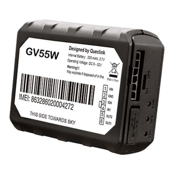
Before starting, check all the following items have been included with your GV55W. If anything is missing, please contact your supplier. FCC ID:YQD-GV55W Figure 1. Appearance of GV55W 2.2. Parts List Table 3. Parts List Name Picture GV55W Locator 63mm*50mm*21.8mm User Cable TRACGV55WUM001 - 7 -... -
Page 9: Interface Definition
Table 4. Description of 6 PIN Connections Index Description Remark External DC power input, 12/24V Ignition input, positive trigger Digital input, negative trigger OUT2 Open drain, 150mA max OUT1 Open drain, 150mA max, with latch circuit TRACGV55WUM001 - 8 -... -
Page 10: Gv55W User Cable Color
GV55W User Manual 2.4. GV55W User Cable Color Table 5. GV55W User Cable Color Definition Definition Color PIN No. Cable Black White Orange OUT2 Green OUT1 Blue TRACGV55WUM001 - 9 -... -
Page 11: Getting Started
Insert the triangular-pry-opener into the gap of the case as shown above, and push the opener up until the case unsnaps. 3.2. Close the Case FCC ID:YQD-GV55W Figure 4. Closing the Case Place the cover on the bottom. Gently slide the cover until it snaps. TRACGV55WUM001 - 10 -... -
Page 12: Install A Sim Card
Take care to align the cut mark. Close the SIM card holder. Close the case. Figure 5. SIM Card Installation 3.4. Install the Internal Backup Battery Figure 6. Backup Battery Installation There is an internal backup Li-ion battery. TRACGV55WUM001 - 11 -... -
Page 13: Switch On The Backup Battery
PWR (PIN1) / GND (PIN2) are the power input pins. The input voltage range for this device is from 8-32 The device is designed to be installed in vehicles that operate on 12/24V vehicle without the need for external transformers. TRACGV55WUM001 - 12 -... -
Page 14: Ignition Detection
For example, the power source for the FM radio. IGN signal can be configured for the device to start transmitting information to backend server when the ignition is on and enter power saving mode when the ignition is off. TRACGV55WUM001 - 13 -... -
Page 15: Digital Input
Typical Digital Input Connection 3.9. Digital Outputs There are two digital outputs on GV55W. Both are of open drain type and the maximum drain current is 150mA. Each output has built-in overcurrent protection self-recovery PTC fuse. TRACGV55WUM001 - 14 -... -
Page 16: Table 8. Electrical Characteristics Of Digital Outputs
GV55W User Manual Figure 11. Digital Output Internal Drive Circuit Table 8. Electrical Characteristics of Digital Outputs Logical State Electrical Characteristics Enable <1.5V @150mA Disable Open drain Figure 12. Typical Connection with Relay TRACGV55WUM001 - 15 -... -
Page 17: Device Status Led
If this diode is not internal, it should be added externally. A common diode such as 1N4004 will work in most circumstances. 3.10. Device Status LED GV55W has three status LEDs that are GSM LED, GPS LED, and PWR LED. TRACGV55WUM001 - 16 -... -
Page 18: Figure 14. Gv55W Led On The Case
2. GPS LED and PWR LED can be configured to turn off after a period of time using the configuration tool. 3. Fast flashing is about 60ms ON/780ms OFF. 4. Slow flashing is about 60ms ON/1940ms OFF. TRACGV55WUM001 - 17 -... -
Page 19: Motion Sensor Direction
FCC Radiation Exposure Statement: This equipment complies with FCC radiation exposure limits set forth for an uncontrolled environment .This equipment should be installed and operated with minimum distance 20cm between the radiator& your body. Queclink Grace Wang Checked TRACGV55WUM001 - 18 - 2018.02.26...
Need help?
Do you have a question about the TRACGV55WUM001 and is the answer not in the manual?
Questions and answers