Advertisement
Quick Links
2194719-3E (Side-A)
S8JX-P (300/600W)
(1/2)
CHN
S8JX
S8JX
S8JX
S8JX-P
(2/2)
OMRON Corporation
©All Rights Reserved
)
370V
30
Fig. 1
Nomenclature
S8JX-P300
3
0
0
W
:
5
4
6
7
3
CHN
Fig.2
Fig.3
DIN
S8JX-P300
CD/ S8JX-P600
CD
Fig.4
6mm
S8JX
100 240 VAC
85 264 VAC 80 370 VDC
EU
UL EN
100 240 VAC
85 264 VAC
UL508
100-240 VAC
"V.ADJ"
–10% +15% 48 V
±10%
1.
2.
"V.ADJ"
3000VAC <
> <
>
1
20mA
1
3000VAC
2
500VDC
EN60950-1 EN50178
S8JX-P600
L
IEC60127
IEC60127
Fig. 2
/Standard mounting
15mm min
15mm min
50mm min
50mm min
CHN
(1)
1.
–25 +75
25 90%
2.
3.
25 85%
4.
5.
6.
7.
8.
9.
(2)
1.
2.
3.
1.6
AWG12 to 20
S8JX-P300
(M4)
2
(
0.517 to 3.309mm )
AWG 6 to 20
(M5)
S8JX-P600
2
(
0.517 to 13.30mm )
60A
60
60/75
4.
75N
5.
(3)
1.
(V.ADJ)
2.
CHN
S8JX-P600
6
0
0
W
:
2
1
1
2
105%
1
2
120%
3
5
3
+S
"V.ADJ"
+20%
+RC –RC
EU
EMC
15mm min
15mm min
CHN
MODEL
S8JX-P (300/600W)
SWITCHING POWER SUPPLY
Fig.2
EN
INSTRUCTION MANUAL (1/2)
Thank you for purchasing the S8JX.
This Instruction Manual describes the functions, performance, and
application methods required to use the S8JX.
Make sure that a specialist with electric knowledge operates the S8JX.
Read and understand this Instruction Manual, and use the product with
enough understanding.
Keep this Instruction Manual close at hand and use it for reference during
operation.
Read the S8JX-P Instruction Manual (2/2) together with this manual
without fail.
OMRON Corporation
©All Rights Reserved
10 in.lb.(1.13 m)
20 in.lb.(2.25 m)
Key to Warning Symbols
Indicates a potentially hazardous situation which, if not
CAUTION
CAUTION
avoided, may result in minor or moderate injury or in
CAUTION
property damage.
CAUTION
Minor electric shock, fire, or Product failure may occasionally
occur. Do not disassemble, modify, or repair the Product or
touch the interior of the Product.
Minor burns may occasionally occur. Do not touch the Product
while power is being supplied or immediately after power is
turned OFF.
Minor fires may occasionally occur. Tighten terminal screws to
a
do not become loose.
Minor injury due to electric shock may occasionally occur. Do not
touch the terminals while power is being supplied. Always close
the terminal cover after wiring.
Working voltage can be 370V max. inside. This voltage can be
also available 30s after the switch off.
Minor electric shock, fire, or Product failure may occasionally
occur. Do not allow any pieces of metal or conductors or any
clippings or cuttings resulting from installation work to enter the
Product.
AC
(
DC
3
DC
(
DC
5
4
6
1. DC
7
2.
category III
3.
4.
EN50178(=VDE0160)
category II
UL60950-1
UL508
Mounting
Fig.2
Standard mounting
Fig.3
Side mounting
Standard mounting (DIN rail)
S8JX-P300
CD/ S8JX-P600
CD
Fig.4
Install the Power Supply so that heat is effectively dissipated to improve and maintain
the reliability of the Power Supply over a long period of time.
A forced-air cooling method with a fan is used.
Do not cover the air holes ( provided at fan mounted
side and the opposite side ) to have enough air-cooling.
The screws must not protrude more than 6mm inside the Power Supply when screw holes
provided on the chassis are used. Mounting screw tightening torque screw holes
(recommended value):1.27
m
Derating Curve
For Derating Curve, refer to the S8JX Catalog.
Selecting input Voltage
Rating:
100 to 240 VAC (allowable range: 85 to 264 VAC, 80 to 370 VDC)
Note:
The applicable range of EU directives and various safety standards (UL, EN, others) is 100 to
240 VAC (85 to 264 VAC).
For UL508 only, the rating is 100-240 VAC.
Output Voltage Adjustment
Default Setting: Set at the rated voltage.
Adjustable Range: Adjustable from –10% to +15% (±10% on the 48 V type) of the rated voltage
using "V.ADJ "
on the front of the unit.
Turning clockwise increases the output voltage, and turning counterclockwise decreases the
output voltage.
Notes:
1.Do not exceed the rated output capacity and current after adjusting the output voltage.
2.The output voltage may increase beyond the allowable voltage range when the operation is
performed for "V.ADJ"
. When adjusting the output voltage, check the output voltage of the
power supply and be sure that the load is not destroyed.
Dielectric Strength Test
Rated dielectric strength:
–S
3000VAC between <input terminals
together > and <output terminals
minute. When testing, set the cutoff current for the withstand voltage test device to 20mA.
Notes:
1.Sudden switching of 3000VAC may possibly cause a voltage surge, damaging the power
supply. Increase/decrease test voltage gradually.
2.When performing the test, be sure to short-circuit all the output terminals to protect them from
damage.
Insulation Resistance Test
When testing the insulation resistance of the power supply, use a DC ohmmeter at 500VDC.
Note:
When performing the test, be sure to short-circuit all the output terminals to protect them from
damage.
EN 60950-1 and EN 50178 Requirement to the customer:
Customers must insert an approved (IEC 60127) high-breaking-capacity fuse in front of the
power supply S8JX-P600
on the (L) side, as the fuse in this power supply does not
comply with IEC 60127.
Fig. 3
/ Side mounting
50mm min
50mm min
/
CHN
EN
Precautions for Safe Use
(1) Installing/Storage Environment
Store the product with ambient temperature –25 to +75°C, and relative
1.
humidity 25 to 90%.
2. The internal parts may occasionally deteriorate and be broken due to
adverse heat radiation depending on the mounting status.
Do not use at a temperature that exceeds the operating temperature range
for the mounting type.
3. The internal parts may occasionally be deteriorated or broken. Do not use
the product in the condition over the operation ambient temperature range.
4. Use the product where the relative humidity is 25 to 85%.
5. Avoid places where the product is subjected to direct sunlight.
6. Avoid places where the product is subjected to penetration of liquid, foreign
substance, or corrosive gas.
7. Avoid places subject to shock or vibration.
A device such as a contact breaker may be a vibration source. Set the
Power Supply as far as possible from possible sources of shock or vibration.
8. If the Power Supply is used in an area with excessive electronic noise,be
sure to separate the Power Supply as far as possible from the noise
sources.
9. The internal parts may occasionally deteriorate and be broken due to
adverse heat radiation.Do not loosen the screws on the Power Supply.
(2) Arrangement/Wiring
1. Connect the ground completely. A protective earthing terminal stipulated in
safety standards is used. Electric shock or malfunction may occur if the
ground is not connected completely.
2.
The light ignition may possibly be caused. Ensure that input and output
terminals are wired correctly.
3. Use the following wiring meterial to prevent smoking or ignition of wiring
material caused by abnormal loads.
Over heating or fire can result from inadequately sized wiring materials when
problems occur at the load. As a general rule, always select wire sizes
suitable for at least 1.6 times the rated current. Refer to the wiring
manufacturer's recommended allowable current and voltage drop
specifications for information when selecting wiring materials.
Model
Terminal
S8JX-P300
Input (M4)
S8JX-P600
Output (M5)
The current rating for the output terminal is 60A per terminal. Make sure to use two terminals
together if a current exceeding the terminal rating is used.
60°C or 60/75°C wire.
4. Do not apply more than 75 N force to the terminal block when tightening it.
5. Be sure to remove the sheet covering the product for machining before
power-on.
(3)
Output Voltage Adjustment
1. The output voltage adjuster (V.ADJ) may possibly be damaged. Do not add
unnecessary power.
2. Do not exceed the rated output capacity and current after adjusting the
output voltage.
EN
Omron Companies shall not be responsible for conformity with any standards, codes or
regulations which apply to the combination of the Product in the Buyer' s application or use of
the Product. At Buyer' s request, Omron will provide applicable third party certification
documents identifying ratings and limitations of use which apply to the Product. This information
by itself is not sufficient for a complete determination of the suitability of the Product in
combination with the end product, machine, system, or other application or use. Buyer shall be
solely responsible for determining appropriateness of the particular Product with respect to
Buyer' s application, product or system. Buyer shall take application responsibility in all cases.
NEVER USE THE PRODUCT FOR AN APPLICATION INVOLVING SERIOUS RISK TO
LIFE OR PROPERTY OR IN LARGE QUANTITIES WITHOUT ENSURING THAT THE
SYSTEM AS A WHOLE HAS BEEN DESIGNED TO ADDRESS THE RISKS, AND THAT
THE OMRON PRODUCT(S) IS PROPERLY RATED AND INSTALLED FOR THE
INTENDED USE WITHIN THE OVERALL EQUIPMENT OR SYSTEM.
CHN
(L) (N)
AC input terminal (L), (N)
(L)
)
(The fuse is located on the (L) side.)
For DC input, (L) side must be (+).
(L)
(+)
Note:
DC input is out of the scope of safety standard certificate.
Protective earthing terminal (
(
)
(A protective earthing terminal stipulated in safety standards is
)
used. Connect the ground completely.)
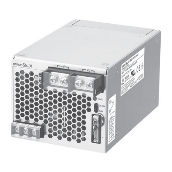
(–V) (+V)
Fig.1
DC output terminal (–V), (+V)
(DC ON
)
Output indicator (DC ON: green)
(V.ADJ)
Output voltage adjuster (V.ADJ)
Alarm indicator (ALM: red)
(ALM
)
Signal input/output connector Instruction Manual (2/2)
(2/2)
CHN
) AC
( )
1.DC output terminals ( ) are galvanically isolated from the AC input
(
Fig.1
terminals ( ).
2.Overvoltage category
1
3.This equipment is for protection class 1.
3K3
4.Climatic class: 3K3
: According to EN50178(=VDE0160).
Overvoltage category II.
: According to UL60950-1 and EN60950-1.
EN60950-1
Surrounding Air Temperature
( Surrounding Air Temperature ) 40
Precautions for Correct Use
EN
Overload Protection
The load and the power supply are automatically protected from overcurrent damage by this
function.
Overload protection is activated if the output current rises above 105% of the rated current.
When the output current returns within the rated range, overload protection is automatically
cleared.
Notes:
1. If operation is continued when the Power Supply has been short-circuited or in an overcurrent
status, internal parts in the Power Supply may occasionally deteriorate or be damaged.
2.The internal parts may possibly be deteriorated or damaged. Do not use the product for
applications where the load causes frequent inrush current and overload.
Overvoltage Protection
This power supply automatically protects itself and the load from overvoltage.
Overvoltage protection is activated if the output voltage rises above approx.
120% of the rated output voltage. The alarm indicator lights simultaneously.
To reset the power supply, leave the power supply off for more than 3 minutes and then turn it on
again.
Note:
Be sure to clear the cause of the overvoltage, before turning on the power supply.
Overheat Protection
If the temperature inside the power supply rises abnormally due to the ambient temperature rising
or the fan stopping, the overheat protection circuit activates and stops output to protect the power
supply unit.
To reset, turn off the input power, allow the unit to cool sufficiently, and then turn on the input
power again.
If There Is No Output Voltage
The overload, overvoltage, or overheat protection functions may be operating. Alternatively,
the built-in fan may be stopped or the remote control function may be OFF. Check the following
five possible causes and contact your OMRON representative if there is still no output voltage.
Check whether the load is in overload status or is shorted.
Remove wires to load when checking.
Turn input power OFF and leave it OFF for at least 3 minutes.
Then turn it ON again to see if this clears the condition. Check if the +S pin or –S pin is opened.
Check if the output voltage is adjusted to more than +20% of the ratedvalue with "V.ADJ"
Turn OFF the input power and leave it OFF until the product cools sufficiently. Turn it ON again
together> for 1
to see if this clears the condition.
Check if the built-in fan motor has stopped. The fan is a consumable product.
Check if the +RC and –RC pins are open. Make the correct connections as specified.
Conformance to EU Directives
Refer to the catalogue and this instruction manual for details on the operating condition for
EMC-compliance.
Fig. 4
DIN
/Standard mounting (DIN rail)
DIN
/When mounting on DIN rails, use iron DIN rails.
Fig.2
Recommended Wire Type
Torque
AWG12 to 20
10 in.lb.(1.
m)
2
(Cross section 0.517 to 3.309mm )
AWG6 to 20
20 in.lb.(2.
m)
(Cross section 0.517 to 13.30mm )
2
y.(The stripping length is 7 to 8 mm for input terminals.)
Suitability for Use
Nomenclature
EN
)
Fig.1
EN
Safety standards
Fig.1
III
.
according to
UL508:40 °C
.
DIN
Advertisement

Related Manuals for Omron S8JX-P300 Series


Summary of Contents for Omron S8JX-P300 Series
- Page 1 OFF. Check the following using "V.ADJ " on the front of the unit. five possible causes and contact your OMRON representative if there is still no output voltage. Turning clockwise increases the output voltage, and turning counterclockwise decreases the output voltage.
- Page 2 2194719-3E (Side-B) (CN) Nomenclature (CN) (+RC) 1: DC (+V) 1: DC output monitor pin (+V) 7: Remote control pin (+RC) (–RC) 8: Remote control pin (–RC) (+S) 2: Remote sensing pin (+S) MODEL S8JX-P 3: DC (–V) 3: DC output monitor pin (–V) 9: No connect 10: No connect (–S)
Need help?
Do you have a question about the S8JX-P300 Series and is the answer not in the manual?
Questions and answers