
Related Manuals for WEG CFW700


Summary of Contents for WEG CFW700
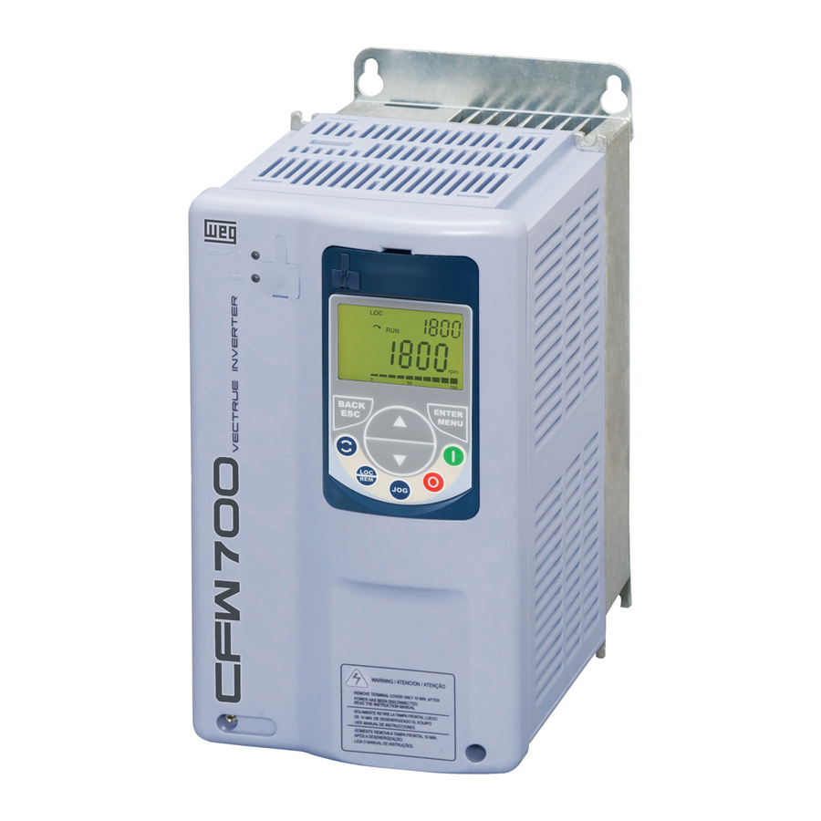
- Page 1 Motors | Automation | Energy | Transmission & Distribution | Coatings Frequency Inverter CFW700 Programming and Troubleshooting Manual...
- Page 3 Programming and Troubleshooting Manual Series: CFW700 Language: English Document Number: 10001006882 / 00 Software Version: 1.0X Publication Date: 06/2011...
-
Page 5: Table Of Contents
2.2.1 Terms and Definitions Used in the Manual ................2-1 2.2.2 Numerical Representation ....................2-3 2.2.3 Symbols for the Parameter Properties Description ............2-3 3 ABOUT THE CFW700 ................3-1 4 KEYPAD (HMI) ..................4-1 5 PROGRAMMING BASIC INSTRUCTIONS ..........5-1 5.1 PARAMETERS STRUCTURE ...................... - Page 6 Summary 11 VECTOR CONTROL ................11-1 11.1 SENSORLESS CONTROL AND WITH ENCODER ..............11-1 11.2 I/f MODE (SENSORLESS) ......................11-5 11.3 SELF-TUNING ..........................11-5 11.4 OPTIMAL FLUX FOR SENSORLESS VECTOR CONTROL ............11-6 11.5 TORQUE CONTROL ........................11-7 11.6 OPTIMAL BRAKING ........................11-8 11.7 MOTOR DATA ..........................11-10 11.7.1 Adjustment of the Parameters P0409 to P0412 Based on the Motor Data Sheet ..
- Page 7 Summary 16 READ ONLY PARAMETERS ............... 16-1 16.1 FAULT HISTORY ......................... 16-8 17 COMMUNICATION ................17-1 17.1 RS-232 AND RS-485 SERIAL INTERFACE ................17-1 17.2 CAN INTERFACE – CANOPEN/DEVICENET ................17-1 17.3 PROFIBUS DP INTERFACE ......................17-2 17.4 COMMUNICATION STATES AND COMMANDS ...............17-4 18 SOFTPLC [50] ..................
- Page 8 Summary...
- Page 9 16-5 P0038 Encoder Speed 0 to 65535 rpm READ 16-5 P0039 Encoder Pulse Counter 0 to 40000 READ 16-6 P0042 Powered Time 0 to 65535 h READ 16-6 P0043 Enabled Time 0.0 to 6553.5 h READ 16-6 CFW700 | 0-1...
- Page 10 0 to 100 % 10 % 12-5 P0133 Minimum Speed 0 to 18000 rpm 90 (75) rpm BASIC 12-6 19-9 19-18 19-21 P0134 Maximum Speed 0 to 18000 rpm 1800 (1500) rpm BASIC 12-6 19-9 19-18 19-21 0-2 | CFW700...
-
Page 11: Quick Parameter Reference, Faults And Alarms
0 to 480 V 440 V Vector 11-18 P0191 Encoder Zero Search 0 = Inactive 0 = Inactive 12-22 1 = Active P0192 Encoder Zero Search Status 0 = Inactive 0 = Inactive READ 12-22 1 = Finished CFW700 | 0-3... - Page 12 0 = Inactive 12-7 1 = Active P0218 Condition to Leave Zero 0 = Reference or Speed 0 = Reference or 12-7 Speed Disable 1 = Reference Speed P0219 Delay for Zero Speed 0 to 999 s 12-8 Disable 0-4 | CFW700...
- Page 13 1 = Coast to Stop 2 = Fast Stop 3 = By Ramp with Iq = 0 4 = Fast Stop with Iq = 0 P0230 Analog Input Dead Zone 0 = Inactive 0 = Inactive 13-1 1 = Active CFW700 | 0-5...
- Page 14 1 = 4 to 20 mA 20 mA 19-9 2 = 10 V / 20 mA to 0 3 = 20 to 4 mA P0254 AO2 Function Refer to the P0251 options 5 = Output current 13-6 19-9 0-6 | CFW700...
- Page 15 19-18 19-22 19-26 19-30 P0269 DI7 Function Refer to the P0263 options 0 = Not Used 13-9 19-10 19-18 19-26 19-30 P0270 DI8 Function Refer to the P0263 options 0 = Not Used 13-10 19-10 19-18 19-30 CFW700 | 0-7...
- Page 16 18 (15) rpm 12-8 13-21 P0292 N = N* Band 0 to 18000 rpm 18 (15) rpm 13-21 P0293 Tx Torque 0 to 200 % 100 % 13-22 P0294 Hx Time 0 to 6553 h 4320 h 13-22 0-8 | CFW700...
- Page 17 1 = 8 bits, even, 1 17-1 1 = 8 bits, even, 1 2 = 8 bits, odd, 1 3 = 8 bits, no, 2 4 = 8 bits, even, 2 5 = 8 bits, odd, 2 CFW700 | 0-9...
- Page 18 2 = HS-CT, Int-CT 15-10 1 = HS-ON, Int-ON 2 = HS-CT, Int-CT 3 = HS-CT, Int-OFF 4 = HS-CT, Int-ON 5 = HS-ON, Int-OFF 6 = HS-ON, Int-CT 7 = HS-OFF, Int-ON 8 = HS-OFF, Int-CT 0-10 | CFW700...
- Page 19 3 = Run for T 4 = Estimate T P0409 Stator Resistance 0.000 to 9.999 ohm 0.000 ohm cfg, V V W MOTOR 10-4 11-13 Vector 11-21 P0410 Magnetization Current 0 to 1.25 x I MOTOR 10-4 nom-ND nom-ND 11-13 11-22 CFW700 | 0-11...
- Page 20 6 = No Bus Power P0706 Received CAN Telegrams 0 to 65535 17-1 P0707 Transmitted CAN Telegrams 0 to 65535 17-1 P0708 Bus Off Counter 0 to 65535 17-1 P0709 Lost CAN Messages 0 to 65535 17-2 0-12 | CFW700...
- Page 21 0 to 1199 17-3 P0755 Profibus Writing # 8 0 to 1199 17-3 P0756 Profibus Writing # 9 0 to 1199 17-3 P0757 Profibus Writing # 10 0 to 1199 17-3 P0918 Profibus Address 1 to 126 17-3 CFW700 | 0-13...
- Page 22 19-27 19-30 P1011 SoftPLC Parameter 2 -32768 to 32767 SPLC 18-2 19-11 19-19 19-22 P1012 SoftPLC Parameter 3 -32768 to 32767 SPLC 18-2 19-11 19-19 19-23 P1013 SoftPLC Parameter 4 -32768 to 32767 SPLC 18-2 19-11 19-23 0-14 | CFW700...
- Page 23 18-2 P1053 SoftPLC Parameter 44 -32768 to 32767 SPLC 18-2 P1054 SoftPLC Parameter 45 -32768 to 32767 SPLC 18-2 P1055 SoftPLC Parameter 46 -32768 to 32767 SPLC 18-2 P1056 SoftPLC Parameter 47 -32768 to 32767 SPLC 18-2 CFW700 | 0-15...
- Page 24 Adj = Parameter available only in adjustable V/f mode. VVW = Parameter available in VVW mode. Vector = Parameter available in vector mode. Sless = Parameter available only in sensorless mode. Enc = Parameter available only in vector mode with encoder. 0-16 | CFW700...
- Page 25 Ground Fault between the inverter and the motor or in the Motor cable capacitance is too large, resulting in current „ motor itself. peaks at the output. Note: It can be disabled by setting P0343 = 0. CFW700 | 0-17...
- Page 26 It indicates an error in the access to the Profibus Verify whether the Profibus DP module is correctly fit „ Profibus DP Module DP communication module data. into the slot 3. Access Error Refer to the Profibus DP communication manual for „ more information. 0-18 | CFW700...
- Page 27 Bad contact at the connection of the signal to the „ terminal strip. A170: The Safety Stop function is active. The CFW700 went to the STO state. „ Safety Stop A177: Fan replacement alarm (P0045 > 50000 hours). The heatsink fan maximum number of operating hours „...
- Page 28 A bad contact in the HMI cable, or electric noise in the installation, can cause a failure in the communication between the HMI and the control board. In such case, the operation through the HMI becomes impossible and the HMI indicates the following message on the display: 0-20 | CFW700...
-
Page 29: Safety Notices
Safety Notices 1 SAFETY NOTICES This Manual contains the information necessary for the correct use of the CFW700 Frequency Inverter. It has been developed to be used by qualified personnel with suitable training or technical qualification for operating this type of equipment. -
Page 30: Preliminary Recommendations
NOTE! For the purposes of this manual, qualified personnel are those trained to be able to: 1. Install, ground, energize and operate the CFW700 according to this manual and the effective legal safety procedures. 2. Use protection equipment according to the established standards. -
Page 31: General Information
This manual presents the necessary information for the configuration of all of the functions and parameters of the CFW700 Frequency Inverter. This manual must be used together with the CFW700 user's manual. The text intents to supply additional information to facilitate the use and programming of the CFW700 in specific applications. - Page 32 Hz. mA: milliamp=0.001 Amp. min: minute. ms: millisecond=0.001 second. Nm: Newton meter; torque measurement unit. rms: “Root mean square”; effective value. rpm: revolutions per minute: speed measurement unit. s: second. V: Volts. Ω: Ohms. 2-2 | CFW700...
-
Page 33: Numerical Representation
Parameter visible on the keypad (HMI) only in the VVW mode: P0202=3. Sless Parameter visible on the keypad (HMI) only in the vector sensorless mode: P0202=4. Encoder Parameter visible on the keypad (HMI) only in the vector with encoder mode: P0202=5. CFW700 | 2-3... - Page 34 General Information 2-4 | CFW700...
-
Page 35: About The Cfw700
About the CFW700 3 ABOUT THE CFW700 The CFW700 is a high performance frequency inverter that makes it possible the control of speed and torque of three-phase AC induction motors. The principal characteristic of this product is the “Vectrue” technology, which presents the following advantages: Scalar control (V/f), V V W or vector control programmable in the same product. - Page 36 (Slot 3 – Green) with Inputs 32-bit (AI1 and AI2) “RISC” Analog Outputs FLASH (AO1 and AO2) Memory Module Digital Outputs (Slot 5) DO1 (RL1) Digital Outputs DO2 to DO5 ƒ=Human-Machine Interface Figure 3.1: CFW700 block diagram 3-2 | CFW700...
- Page 37 3 - Fan with fixing support 4 - Control accessory module (refer to section 7.2 - Accessories, of the CFW700 user's manual) 5 - FLASH memory module (not included) 6 - Front cover (sizes A, B and C) 7 - Keypad (HMI)
- Page 38 About the CFW700 3-4 | CFW700...
-
Page 39: Keypad (Hmi)
Keypad (HMI) 4 KEYPAD (HMI) The integral keypad can be used to operate and program (view / edit all parameters) of the CFW700 inverter. There are two operation modes in the keypad: monitoring and programming. The key functions and display indications of the keypad may change according to the operation mode. - Page 40 Keypad (HMI) Figure 4.2: Back of the keypad (HMI) Installation: The keypad (HMI) can be installed or removed with the inverter energized. „ 4-2 | CFW700...
-
Page 41: Programming Basic Instructions
5.1 PARAMETERS STRUCTURE In order to make the programming of the inverter easier, the parameters of the CFW700 were divided into 10 groups that can be individually selected in the Menu area of the keypad. When the ENTER/MENU key is pressed on monitoring mode, the programming mode is set. -
Page 42: Password Setting In P0000
Press the BACK/ESC key to go back to the 2° level of programming mode. Press the BACK/ESC key in order to go back to the monitoring mode. Monitoring mode. Figure 5.1: Sequence for allowing parameter changes via P0000 5-2 | CFW700... -
Page 43: Hmi
Access groups via HMI: Description: These parameters define which parameters are displayed on the keypad in the monitoring mode. More details on the programming can be seen in section 5.5 - Display Indications in the Monitoring Mode Settings. CFW700 | 5-3... - Page 44 This parameter selects the engineering unit to be presented in the main display. The content of this parameter is automatically adjusted to match the unit of the parameter selected by P0205 when its value is changed by the HMI. 5-4 | CFW700...
-
Page 45: Display Indications In The Monitoring Mode Settings
Main Display (selected by P0205). Displays the content of parameter (Pxxxx), value of parameter (Pxxxx), Fault indication (Fxxx) or Alarm (Axxx). Bar Graph for parameter monitoring (selected by P0207). Figure 5.2: Screen at startup and display indication CFW700 | 5-5... -
Page 46: Incompatibility Between Parameters
Programming Basic Instructions 5.6 INCOMPATIBILITY BETWEEN PARAMETERS If any of the combinations listed below occur, the CFW700 goes to the “Config” state. 1. Two or more DIx (P0263...P0270) programmed for (8 = FWD/REV). 2. Two or more DIx (P0263 ..P0270) programmed for (9 = LOC/REM). -
Page 47: Inverter Model And Accessories Identification
Figure 6.1 (a) and (b): Nameplates Once the inverter model identification code is verified, one must interpret it in order to understand its meaning. Refer to the section 2.3 - Identification, of the CFW700 user's manual. 6.1 INVERTER DATA In this group are the parameters related to the inverter information and characteristics, such as inverter model, accessories identified by the control circuit, software version, switching frequency, etc. - Page 48 Those parameters identify by means of a hexadecimal code the accessories that were found installed on the control module. The next table shows the codes shown in those parameters, regarding the main CFW700 accessories. Table 6.1: CFW700 accessory identification codes...
- Page 49 33.5 A 58.5 A 45 A 70.5 A 54 A 88 A 70 A 105 A 86 A 142 A 105 A 180 A 180 A 211 A 211 A 142 A * Models with single-phase/three-phase power supply. CFW700 | 6-3...
- Page 50 Inverter Model and Accessories Identification Example: For a 10 A, 380...480 V CFW700, with RFI suppressor filter, without safety relay and without external 24 V supply, the hexadecimal code presented in the keypad (HMI) for the parameter P0029 is C544 (refer to the table 6.5).
-
Page 51: Vvw Control
NOTE! When adjusted via the keypad (HMI), this parameter may change automatically the following parameters: P0151, P0153, P0185, P0321, P0322 and P0323. Table 6.6: P0296 setting according to the CFW700 inverter model Inverter Model Adjustable Range Factory Setting 200-240 V 0 = 200 ... - Page 52 The I and I are presented in P0295. Refer to the CFW700 user's manual chapter 8 - Technical nom-ND nom-HD Specifications, for more details regarding these operation regimens.
-
Page 53: Starting-Up And Settings
Parameters, described next. 7.1 BACKUP PARAMETERS The CFW700 BACKUP functions allow saving the content of the current inverter parameters in a specific memory, or vice-versa (overwrite the contents of the current parameters with the memory contents). Besides, there is a function exclusive for software update, by means of the FLASH Memory Module. - Page 54 Memory 2 Figure 7.1: Parameter transfer In order to load parameters from User 1 and/or User 2 to the CFW700 operation area (P0204=7 or 8), it is necessary that these areas had been saved previously. The operation of loading one of those memories can also be performed via digital inputs (DIx). Refer to item 13.1.3 - Digital...
- Page 55 P0318 = 3. If you want to copy from another inverter, set P0318 to 0 before inserting the card. NOTE! When the inverter is powered on and the memory module is not detected, P0318 is not visible or changeable by the user and it is automatically set to 0. CFW700 | 7-3...
- Page 56 Starting-up and Settings 7-4 | CFW700...
-
Page 57: Available Control Types
„ regulation or with slip compensation (programmable); it allows multimotor operation. V V W: Voltage Vector WEG; it allows a static speed control more accurate than the V/f mode; it adjusts itself „ automatically to the line variations, and also to the load variations, however it does not present fast dynamic response. - Page 58 Available Control Types 8-2 | CFW700...
-
Page 59: Scalar Control (V/F)
Total Reference Speed (Refer to figure 13.7) P0202=2=Ajustable V/f P0142 P0143 P0144 P0146 P0145 Speed Reference = Output Current TRANSF. P0138 P0137 Automatic Torque BOOST Slip Speed Speed Compensation I active P0139 Figure 9.1: V/f control block diagram CFW700 | 9-1... -
Page 60: V/F Control
Nominal 1/2 nominal P0136=9 P0136=0 Speed nom/2 Figure 9.2: Effect of P0136 on the V/f curve (P0202=0 or 1) P0137 – Automatic Torque Boost Adjustable 0.00 to 1.00 Factory 0.00 Range: Setting: Properties: Access groups via HMI: 9-2 | CFW700... - Page 61 Negative values are used in special applications where one wants to reduce the output speed in function of the increase in the motor current. E.g.: Load distribution in motors operated in parallel. CFW700 | 9-3...
- Page 62 It is used in the Automatic Torque Boost and Slip Compensation functions. Refer to the figures 9.3 and 9.5. It sets the response time of the Slip Compensation and of the Automatic Torque Boost. Refer to the figures 9.3 and 9.5. 9-4 | CFW700...
-
Page 63: Adjustable V/F Curve
Adjustable 0=V/f 60 Hz Factory Range: 1=V/f 50 Hz Setting: 2=V/f Adjustable 3=V V W (Voltage Vector WEG) 4=Sensorless 5=Encoder Properties: Access groups via HMI: Description: In order to get an overview of the control types, as well as orientation to choose the most suitable type for the... - Page 64 If it is necessary to increase the starting torque, increase gradually the value of P0144. Output Voltage Line rated voltage 100 % P0142 P0202=2 P0143 P0144 Speed/ Frequency 0.1Hz P0146 P0145 P0134 Figure 9.7: V/f curve in function of P0142 to P0146 9-6 | CFW700...
-
Page 65: V/F Current Limitation
Working: if the motor current exceeds the value adjusted in P0135, the input of the speed ramp is set to „ zero forcing a deceleration. When the motor current reaches a value below P0135 the motor will accelerate again. Refer to the figure 9.8 (b). CFW700 | 9-7... - Page 66 (P0100) Time Time During During acceleration deceleration (a) “Ramp Hold” Motor current Time P0135 Time Speed Decelerates via ramp P0101 Time (b) “Ramp Deceleration” Figure 9.8 (a) and (b): Current limitation via P0135 working modes 9-8 | CFW700...
-
Page 67: V/F Dc Voltage Limitation
Error < 0: Ramp Hold = inactive Dc link Voltage (U Error ≥ 0: Ramp Hold = active Ramp Hold P0151 Output Input Acceleration/Deceleration Ramp Figure 9.9: Limitation of the DC link voltage using Ramp Acceleration function block diagram CFW700 | 9-9... - Page 68 The use is recommended for loads that require braking torques in constant speed situation. Example: driving of loads with eccentric shafts such as the existent in pumpjacks. P0152 Dc Link Speed Voltage (U Ramp Output P0151 Figure 9.11: Limitation of the DC link voltage using Ramp Acceleration function block diagram 9-10 | CFW700...
- Page 69 P0151 as suggested in the table 9.2. Table 9.2: Recommended actuation levels for the DC link regulation Inverter 220/230 V 380 V 400/415 V 440/460 V 480 V P0296 P0151 375 V 618 V 675 V 748 V 780 V CFW700 | 9-11...
-
Page 70: Start-Up In The V/F Control Mode
1. Install the inverter: according to the chapter 3 - Installation and Connection, of the CFW700 user's manual, wiring all the power and control connections. 2. Prepare the inverter and apply power: according to the section 5.1 - Prepare for Start-Up, of the CFW700 user's manual. -
Page 71: V W Control
V V W Control 10 V V W CONTROL The V V W (Voltage Vector WEG) control mode uses a control method with intermediate performance between V/f and Sensorless Vector. Refer to the figure 10.1 block diagram. The main advantage compared to the V/f control is the better speed regulation with higher torque capability at low speeds (frequencies below 5 Hz), allowing a sensible improvement of the inverter performance in permanent regimen. - Page 72 V V W Control Figure 10.1: V V W control block diagram 10-2 | CFW700...
-
Page 73: W Control
HMI: Description: It sets the motor rated efficiency. This parameter is important for the V V W control precise operation. The inaccurate setting implies in incorrect calculation of the slip compensation and consequently an imprecise speed control. CFW700 | 10-3... - Page 74 The default value of this parameter is adjusted automatically when the parameter P0404 is changed. The suggested value is valid for three-phase, IV pole WEG motors. For other motor types the setting must be done manually.
-
Page 75: W Control Mode Start-Up
1. Install the inverter: according to the chapter 3 - Installation and Connection, of the CFW700 user's manual, wiring all the power and control connections. 2. Prepare the inverter and apply power: according to the section 5.1 - Prepare for Start-up, of the CFW700 user's manual. - Page 76 P0134, P0135, P0182, P0208, P0288 the IGBT overload protection will also and P0289. be affected. Pre ss the key to the nex t Pre ss the key to the nex t parameter. parameter. Figure 10.2: V V W mode Oriented Start-up 10-6 | CFW700...
- Page 77 P0408 is automatically set back to zero. Press BACK/ESC key to finish the start-up routine. Press BACK/ESC key again to get back to the monitoring mode. Figure 10.2 (cont.): V V W mode Oriented Start-up CFW700 | 10-7...
- Page 78 V V W Control 10-8 | CFW700...
-
Page 79: Vector Control
Another advantage of this control type is the greater robustness against sudden line voltage and load changes, avoiding unnecessary overcurrent trips. The necessary settings for the good operation of the sensorless vector control are done automatically. Therefore the used motor must be connected to the CFW700 inverter. CFW700 | 11-1... - Page 80 Vector Control Figure 11.1: Sensorless vector control block diagram 11-2 | CFW700...
- Page 81 Speed control accuracy of 0.01 % (if digital references are used, for instance via keypad (HMI), Profibus DP, „ DeviceNet, etc.). Refer to the user's manual for more details about the installation and connection of the incremental encoder. CFW700 | 11-3...
- Page 82 Vector Control Figure 11.2: Vector with encoder control block diagram 11-4 | CFW700...
-
Page 83: I/F Mode (Sensorless)
WEG motors. In the option P0408=1 (No Rotation) the motor remains stopped throughout the self-tuning. The magnetizing current value (P0410) is obtained from a table, valid for WEG motors up to 12 poles. In the option P0408=2 (Run for I ) the value of P0410 is estimated with the motor rotating and the load decoupled from the motor shaft. -
Page 84: Optimal Flux For Sensorless Vector Control
„ the Parameters P0409 to P0412 Based on the Motor Data Sheet, of this manual. Manually, by copying the contents of the parameters from another CFW700 inverter that uses an identical „ motor. 11.4 OPTIMAL FLUX FOR SENSORLESS VECTOR CONTROL NOTE! Active function only on the Sensorless Vector mode (P0202=4), if P0406=2. -
Page 85: Torque Control
In the vector with encoder control type set the speed regulator for the mode “optimized for torque „ control” (P0160=1), besides keeping it saturated. NOTE! The motor rated current must be equivalent to the CFW700 rated current, in order that the torque control has the best possible accuracy. CFW700 | 11-7... -
Page 86: Optimal Braking
TB1 point on the figure 11.3. The value of TB1 is on the function of the motor efficiency, and it is defined by the following expression, being despised the attrition losses: TB1 = 1-η η Where: η = motor efficiency. 11-8 | CFW700... - Page 87 2. In order to enable and disable the Optimal Braking via a digital input, set one of the inputs (DIx) for “DC Link Regulation”. (P0263…P0270=16 and P0184=2). Results: DIx=24 V (closed): Optimal Braking is active, equivalent to P0184=0. DIx=0 V (open): Optimal Braking is inactive. CFW700 | 11-9...
-
Page 88: Motor Data
This value cannot be higher than the rated voltage adjusted in P0296 (Line Rated Voltage). NOTE! In order to validate a new P0400 setting out of the Oriented Start-up Routine it is necessary to cycle the power of the inverter. 11-10 | CFW700... - Page 89 Set it according to the used motor nameplate data. For V/f and V V W controls the setting range goes up to 300 Hz. For vector control the setting range is from 30 Hz to 120 Hz. CFW700 | 11-11...
- Page 90 Start. P0405 – Encoder Pulse Number Adjustable 100 to 9999 ppr Factory 1024 ppr Range: Setting: Properties: Access groups MOTOR via HMI: Description: It sets the number of pulses per rotation (ppr) of the used incremental encoder. 11-12 | CFW700...
- Page 91 P0410 – Motor Magnetization Current (I P0411 – Motor Flux Leakage Inductance (σls) P0412 – Lr/Rr Constant (Rotor Time Constant – T P0413 – T Constant (Mechanical Time Constant) Self-Tuning function parameters. Refer to item 11.8.5 - Self-Tuning. CFW700 | 11-13...
-
Page 92: Adjustment Of The Parameters P0409 To P0412 Based On The Motor Data Sheet
ω P0400 x (X P0412 = x ω x R 11.8 VECTOR CONTROL 11.8.1 Speed Regulator The parameters related to the CFW700 speed regulator are presented in this group. P0160 – Speed Regulation Optimization Adjustable Factory 0 = Normal Range:... - Page 93 7. Adjust P0161 and P0162 according to the response type presented in the figure 11.4. (a) Reduce the proportional gain (P0161) and/or increase the integral gain (P0162). (b) Speed regulator is optimized. (c) Increase the proportional gain and/or reduce the integral gain. CFW700 | 11-15...
- Page 94 The differential action may minimize the effects of the application or removal of load, in the motor speed. Refer to the figure 11.2. Table 11.3: Differential gain action in the speed regulator P0166 Diferential Gain Actuation 0.00 Inactive 0.01 to 7.99 Active 11-16 | CFW700...
-
Page 95: Current Regulator
Vector Control 11.8.2 Current Regulator The parameters related to the CFW700 current regulator are presented in this group. P0167 – Current Regulator Proportional Gain Adjustable 0.00 to 1.99 Factory 0.50 Range: Setting: P0168 – Current Regulator Integral Gain Adjustable Factory 0.000 to 1.999... - Page 96 If this voltage increases, the output voltage will then be able to increase to the adjusted value in the parameter P0400 - Motor Rated Voltage. If the voltage supply decreases, the maximum output voltage will decrease in the same proportion. 11-18 | CFW700...
-
Page 97: I/F Control
Table 11.4: Current applied in the I/f mode P0183 Current in the I/f Mode as a Percentage of P0410 (I 100 % 111 % 122 % 133 % 144 % 155 % 166 % 177 % 188 % 200 % CFW700 | 11-19... -
Page 98: Self-Tuning
P0413 P0408=1 – No rotation: The motor stands still during the self-tuning. The P0410 value is obtained from a table, valid for WEG motors up to 12 poles. NOTE! Therefore P0410 must be equal to zero before initiating the self-tuning. If P0410≠0, the self-tuning routine will keep the existent value. - Page 99 The parameter P0413 (Mechanic time constant – T ) will be adjusted to a value close to the motor mechanic time constant. Therefore, the motor rotor inertia (table data valid for WEG motors), the inverter rated voltage and current are taken into consideration.
- Page 100 WEG motors, when P0408=1 (No rotation). When a standard WEG motor is not used and it is not possible to run the self-tuning with P0408=2 (Run for I then adjust P0410 with a value equal to the motor no load current, before initiating the self-tuning.
- Page 101 In the sensorless vector control mode the P0175 gain, provided by the self-tuning, will be limited in the range: 3.0 ≤ P0175 ≤ 8.0. Table 11.6: Typical rotor constant (T ) values for WEG motors Motor Power Number of Poles...
- Page 102 „ current step equal to the motor rated current. In case that it is not possible to submit the load to this type of request, adjust P0413 via keypad (HMI), refer „ item 11.8.1 - Speed Regulator. 11-24 | CFW700...
-
Page 103: Torque Current Limitation
(*) In case that the torque current limitation be provided by an analog input, replace P0169 or P0170 by P0018 or P0019 according to the programmed AIx. For more details refer to item 13.1.1 - Analog Inputs. CFW700 | 11-25... -
Page 104: Dc Link Regulator
Vector Control 11.8.7 DC Link Regulator For the deceleration of high inertia loads or with short deceleration times, the CFW700 has available the DC Link Regulation function, which avoids the tripping of the inverter by overvoltage in the DC link (F022). - Page 105 0.002 Range: Setting: Properties: Vector Access groups via HMI: Description: These parameters adjust the DC link voltage regulator gain. Normally the factory settings are adequate for the majority of the applications, not being necessary to adjust them. CFW700 | 11-27...
-
Page 106: Start-Up In The Vector Modes Sensorless And With Encoder
1. Install the inverter: according to the chapter 3 - Installation and Connection, of the CFW700 user's manual, wiring all the power and control connections. 2. Prepare the inverter and apply power: according to the section 5.1 - Prepare for Start-up, of the CFW700 user's manual. - Page 107 - If necessary, change “P0296 - Press the key to the next Line Rated Voltage”. This change parameter. will affect P0151, P0153, P0185, P0321, P0322, P0323 and P0400. Press the key to the next parameter. Figure 11.5: Vector mode Oriented Start-up CFW700 | 11-29...
- Page 108 P0408 is automatically reset. Press BACK/ESC key to finish the start-up routine. Press BACK/ESC key again to get back to the monitoring mode. Figure 11.5 (Cont.): Vector mode Oriented Start-up 11-30 | CFW700...
-
Page 109: Functions Common To All The Control Modes
Functions Common to all the Control Modes 12 FUNCTIONS COMMON TO ALL THE CONTROL MODES This section describes the functions that are common to all the CFW700 inverter control modes (V/f, V V W, Sensorless, and Encoder). 12.1 RAMPS The inverter RAMPS functions allow the motor to accelerate and decelerate in a faster or a slower manner. - Page 110 This parameter allows that the acceleration and deceleration ramps have a nonlinear profile, similar to an “S”, as showed in the figure 12.2 next. Speed Linear S Ramp t (s) Acceleration Time Deceleration Time (P0100/P0102) (P0101/P0103) Figure 12.2: S or linear ramp The S ramp reduces mechanic shock during accelerations/decelerations. 12-2 | CFW700...
-
Page 111: Speed References
If P0120=Inactive, then the inverter will not save the speed reference when it is disabled. Thus, when the inverter is enabled again the speed reference will assume the value of the minimum speed limit (P0133). This backup function applies to the references via keypad (HMI), Serial, CANopen/DeviceNet, SoftPLC. CFW700 | 12-3... - Page 112 For more details refer to the figure 13.5 (h). The speed direction is defined by the parameters P0223 or P0226. The JOG command is effective only with the motor stopped. For the JOG+ refer to the description below. 12-4 | CFW700...
-
Page 113: Speed Limits
This parameter sets the highest speed allowed for the motor to operate, and must be adjusted as a percentage of the maximum speed limit (P0134). When the actual speed exceeds the value of P0134 + P0132 longer than 20 ms, the CFW700 will disable the PWM pulses and indicate the fault (F150). - Page 114 Reference 0 ......100 % 0 ......10 V 0 ..... 20 mA 4 mA ....20 mA 10 V ......0 20 mA ......0 20 mA ....4 mA Figure 12.3: Speed limits considering the “Dead Zone” active (P0230=1) 12-6 | CFW700...
-
Page 115: Zero Speed Logic
P0218, it is necessary that the PID error (the difference between the setpoint and the process variable) is greater than the value set in P1028. Refer to the chapter 19 - Applications, for more details. CFW700 | 12-7... -
Page 116: Flying Start / Ride-Through
1 = Flying Start Setting: 2 = Flying Start / Ride-Through 3 = Ride-Through Properties: Access groups via HMI: Description: The parameter P0320 selects the functions Flying Start and Ride-Through use. More details in the subsequent sections. 12-8 | CFW700... -
Page 117: V/F Or V V W Flying Start
When the general enable command is activated, the motor magnetization will not occur. NOTE! For a better performance of the function, the activation of the braking without losses is recommended by setting the parameter P0185 according to the table 11.8. CFW700 | 12-9... - Page 118 It defines the rate of frequency variation used in the motor speed search. P0329 is determined in function of P0404, as showed in the next table: Table 12.4: P0329 value in function of P0404 P0404 0...20 21...23 24...25 P0329 The frequency variation rate is determined by: (P0329 x P0412). 12-10 | CFW700...
-
Page 119: P0202=5
During the time period when the motor is being magnetized, the identification of the motor speed occurs. Once the magnetization is finished, the motor will be operated starting from that speed until reaching the speed reference indicated in P0001. The parameters P0327 to P0329, P0331 and P0332 are not used. CFW700 | 12-11... -
Page 120: W Or V/F Ride-Through
This parameter sets the necessary time for the output voltage to reach the rated voltage value. It is used by the Flying Start function as well as by the Ride-Through function (both in V/f or V V W modes), together with the parameter P0332. 12-12 | CFW700... -
Page 121: Vector Ride-Through
“DC Link Power Back” (t4) level, defined at the parameter P0323. The motor is then reaccelerated, following the adjusted ramp, from the actual speed value to the value defined by the speed reference (P0001) (refer to the figure 12.6). CFW700 | 12-13... - Page 122 Use oversized high-speed fuses or regular fuses to limit the inrush current when the line returns. „ NOTE! The Ride-Through function activation occurs when the power supply voltage is lower than the value (P0321/1.35). U =Vac x 1.35 12-14 | CFW700...
- Page 123 „ the motor must be reaccelerated. NOTE! These parameters work together with the parameters P0325 and P0326 for the Ride-Through in vector control. CFW700 | 12-15...
- Page 124 R.T. Regulator Block diagram input Ride-Through Figure 11.1 11.2 (P0322) P0325, P0326 Figure 12.7: Ride-Through PI controller Normally the factory settings for P0325 and P0326 are adequate for the majority of the applications. Do not change these parameters. 12-16 | CFW700...
-
Page 125: Dc Braking
Description: This parameter sets the DC braking time at starting. INJECTION OF DIRECT CURRENT AT STARTING Motor Speed Time P0299 P0302/P0372 (V/f, V V W )/(Sensorless) DC Braking Time Stop Figure 12.8: DC braking operation at starting CFW700 | 12-17... - Page 126 (b) V V W and Sensorless Vector DC Current Injection Motor Speed P0300 P0301 Time +24 V DIx - Run/ Stop Open Figure 12.9 (a) and (b): DC braking operation at the ramp disabling (via ramp disable) 12-18 | CFW700...
- Page 127 30 rpm Range: Setting: Properties: V/f, V V W and Sless Access groups via HMI: Description: This parameter establishes the beginning point for the DC braking application at stopping. Refer to the figures 12.9 (a) and (b). CFW700 | 12-19...
- Page 128 This parameter adjusts the current level (DC braking torque) applied to the motor during the braking. The programmed current level is a percentage of the inverter rated current. This parameter works only in the Sensorless Vector control mode. 12-20 | CFW700...
-
Page 129: Skip Speed
The passage through the avoided speed range (2xP0306) takes place by means of the acceleration/deceleration ramps. The function does not operate properly if two bands of “Skip Speed” overlap. Motor speed P0305 2 x P0306 P0304 2 x P0306 P0303 Speed Reference Figure 12.11: “Skip Speed” actuation curve CFW700 | 12-21... -
Page 130: Search Of Zero Of The Encoder
On the inverter initialization, this parameter starts on zero. When the value is changed to 1 (Finished), it indicates that the zero search function was executed, and this function returns to the state of Inactive, although P0191 continues equal to one (Active). 12-22 | CFW700... -
Page 131: Digital And Analog Inputs And Outputs
Digital and Analog Inputs and Outputs 13 DIGITAL AND ANALOG INPUTS AND OUTPUTS This section presents the parameters for the configuration of the CFW700 inputs and outputs, as well as the parameters for the command of the inverter in the Local or Remote Situations. - Page 132 6 = Application Function 2 7 = Application Function 3 8 = Application Function 4 9 = Application Function 5 10 = Application Function 6 11 = Application Function 7 12 = Application Function 8 Properties: Access groups via HMI: 13-2 | CFW700...
- Page 133 19 - Applications. P0232 – AI1 Gain P0237 – AI2 Gain Adjustable 0.000 to 9.999 Factory 1.000 Range: Setting: P0234 – AI1 Offset P0239 – AI2 Offset Adjustable Factory -100.00 to 100.00 % 0.00 % Range: Setting: CFW700 | 13-3...
- Page 134 AIx function is “Speed Reference”. For the AIx function “Maximum Torque Current”, negative values are clipped at 0.0 %. For the filter parameters (P0235 and P0240), the adjusted value corresponds to the RC constant used for filtering the signal read at the input. 13-4 | CFW700...
-
Page 135: Analog Outputs
Inverse reference is obtained with the options 2 and 3, i.e., maximum speed is obtained with minimum reference. 13.1.2 Analog Outputs In the CFW700 standard configuration are available 2 analog outputs (AO1 and AO2). The parameters related to those outputs are described next. - Page 136 These parameters set the functions of the analog outputs. P0252 – AO1 Gain P0255 – AO2 Gain Adjustable 0.000 to 9.999 Factory 1.000 Range: Setting: Properties: Access groups via HMI: Description: They adjust the analog output gains. Refer to the figure 13.3. 13-6 | CFW700...
- Page 137 Encoder Speed P0696 Value P0697 Value Id* Current Application Function 1 Application Function 2 Application Function 3 Application Function 4 Application Function 5 Application Function 6 Application Function 7 Application Function 8 Figure 13.3: Analog output block diagram CFW700 | 13-7...
- Page 138 (10 to 0) V / (20 to 0) mA On / Off (20 to 4) mA For AO1 and AO2, when current signals are used, the switch corresponding to the desired output must be set in the “OFF” position. 13-8 | CFW700...
-
Page 139: Digital Inputs
Digital and Analog Inputs and Outputs 13.1.3 Digital Inputs The CFW700 has 8 digital inputs in the standard version. The parameters that configure those inputs are presented next. P0012 – DI8 to DI1 Status Adjustable Bit 0 = DI1 Factory... - Page 140 (*) The speed regulator of the PID type is converted into a P type, with proportional gain 1.00 and a null integral gain. When Speed is selected, the gains of the speed regulator become again defined by P0161 and P0162. In the applications with torque control it is recommended to follow the method described at the parameter P0160. 13-10 | CFW700...
- Page 141 (HMI) display. The motor keeps working normally, regardless of the state of that input. Application Function: Sets the input to be used by the applications. For more details, refer to chapter „ 19 - Applications. CFW700 | 13-11...
- Page 142 Fast Stop, Forward Run or Reverse Run must be in the ON Stop, Forward Run or Reverse Run must be in the ON state, so that the CFW700 operates as described above. state, so that the CFW700 operates as described above.
- Page 143 Without fault status Time 24 V Open DIx - Reset Time 24 V Reset (*) The condition that caused the error persists. Time Figure 13.5 (h) to (j) (cont.): Details on the operation of the digital input functions CFW700 | 13-13...
-
Page 144: Digital Outputs / Relays
Digital and Analog Inputs and Outputs 13.1.4 Digital Outputs / Relays The CFW700 has one digital output relay and 4 open collector outputs available in the control board as standard. The next parameters configure the functions related to those outputs. - Page 145 When the condition declared by the function is true, the digital output will be activated. Example: Is>Ix function – when Is>Ix then DOx=saturated transistor and/or relay with the coil energized, and when Is≤Ix then DOx=open transistor and/or relay with the coil not energized. CFW700 | 13-15...
- Page 146 P0695 Value: it means that the state of the digital output will be controlled by P0695, which is written via the „ network. Refer to the CFW700 Serial communication manual for more details on this parameter. Forward: it means that when the motor is rotating in the forward direction the DOx=saturated transistor and/or „...
- Page 147 Nt = Total Reference (refer to the figure 13.7). Hx = P0294 (Hx Time). F = P0005 (Motor Frequency). Fx = P0281 (Fx Frequency) – It is a reference point of the motor frequency selected by the user. CFW700 | 13-17...
- Page 148 (h) Torque > Tx (g) Is < Ix Motor Torque (P0009) Tx (P0293) Ix (P0290) Time Time Relay/ Relay/ Transistor Transistor Figure 13.6 (a) to (h): Details on the operation of the digital and relay output functions 13-18 | CFW700...
- Page 149 (o) N > Nx and Nt > Nx (p) F > Fx P0281 + P0282 Fx (P0281) Nx (P0288) P0281 - P0282 Time Relay/Transistor Relay Figure 13.6 (i) to (p) (cont.): Details on the operation of the digital and relay output functions CFW700 | 13-19...
- Page 150 Adjustable Factory 0 to 900 rpm 18 rpm Range: Setting: (15 rpm) Properties: Access groups via HMI: Description: It is used in the N > Nx and N < Ny functions of the digital and relay outputs. 13-20 | CFW700...
- Page 151 P0292 – N = N* Band Adjustable 0 to 18000 rpm Factory 18 rpm Range: Setting: (15 rpm) Properties: Access groups via HMI: Description: It is used in the N = N* function of the digital and relay outputs. CFW700 | 13-21...
-
Page 152: Local And Remote Command
It defines the origin of the command that will select between the LOCAL situation and the REMOTE situation, where: LOCAL: Means Local Default situation. „ REMOTE: Means Remote Default situation. „ DIx: Refer to item 13.1.3 - Digital Inputs. „ 13-22 | CFW700... - Page 153 They define the origin of the “Speed Direction” command in the LOCAL situation and in the REMOTE situation, where: FWD: Means Forward Default situation. „ REV: Means Reverse Default situation. „ DIx: Refer to item 13.1.3 - Digital Inputs. „ CFW700 | 13-23...
- Page 154 3 = By Ramp with Iq* 4 = Fast Stop with Iq* Properties: Access groups via HMI: Description: It defines the motor stop mode when the inverter receives the “Stop” command. The table 13.8 describes the options of this parameter. 13-24 | CFW700...
- Page 155 Stop command. The purpose of the options 3 and 4 is to avoid that a high current reference value is stored in the speed regulator when, for instance, using a mechanical brake to stop the motor shaft before its speed is null. CFW700 | 13-25...
- Page 156 Digital and Analog Inputs and Outputs (*) Valid only for P0202=5 and 4. Figure 13.7: Speed Reference block diagram 13-26 | CFW700...
- Page 157 REFERENCE (P0221) FORWARD/REVERSE (P0220) (P0223) LOCAL/REMOTE Selection LOCAL RUN/STOP (P0224) REFERENCE JOG (P0225) REFERENCE REFERENCE REMOTE REFERENCE LOCAL COMMANDS COMMANDS REMOTE COMMANDS REMOTE COMMANDS REFERENCE (P0222) FORWARD/REVERSE (P0226) RUN/STOP (P0227) JOG (P0228) Figure 13.8: Local/Remote situation block diagram CFW700 | 13-27...
- Page 158 Digital and Analog Inputs and Outputs 13-28 | CFW700...
-
Page 159: Dynamic Braking
For the vector control mode there is the possibility of the use of the “Optimal Braking”, eliminating in many cases the need of the dynamic braking. The Dynamic Braking function can only be used if a braking resistor has been connected to the CFW700, and if the parameters related to it have been adjusted properly. - Page 160 Connect the braking resistor. Refer to item 3.2.3.2 - Dynamic Braking (standard built-in for sizes A, B, C and „ D and optional built-in for size E - CFW700...DB...), of the user's manual. Set P0151 at the maximum value: 400 V (P0296=0) or 800 V (P0296=1, 2, 3 or 4), according to the case, in „...
-
Page 161: Faults And Alarms
In order to assure more protection in case of restart, this function keeps the information regarding the motor thermal image in the CFW700 nonvolatile memory. Therefore, after the inverter restart, the function will use the value saved in the thermal memory to perform a new overload evaluation. -
Page 162: Motor Overtemperature Protection
Resets A110 alarm 150 Ω < R <1.6 kΩ 0.3<V <3.2 V Allows the reset of the F078 fault 150 Ω < R <1.6 kΩ 0.3<V <3.2 V F078 trips (minimum resistance detection) <60 Ω <0.12 V 15-2 | CFW700... -
Page 163: Protections
Description: These parameters present, in Celsius degrees, the heatsink temperature (P0030) and also of the internal air (P0034). They are useful to monitor the temperature on the main inverter sections in case of an occasional inverter overheating. CFW700 | 15-3... - Page 164 (motors with separated ventilation). This curve is adjusted automatically when P0406 (Motor Ventilation) is set during the “Oriented Start-up” routine (refer to this parameter description in the section 11.7 - Motor Data). 15-4 | CFW700...
- Page 165 The incorrect selection of the thermal class may cause the burning of the motor. ATTENTION! In order the CFW700 motor overload protection is in accordance with UL508C, the thermal class should be ≤20 (P0159 ≤ 3). The necessary data for choosing the thermal class are the following: Motor rated current (I „...
- Page 166 Class 20 Class 15 Class 10 Class 5 Current x In for F.S = 1.00 Current x In for F.S. = 1.15 Figure 15.3 (a): Cold motor overload curves for loads of the HD and ND types 15-6 | CFW700...
- Page 167 P0340 has elapsed. NOTE! The faults F051, F078 and F156 allow a conditional Reset, i.e., the Reset will only occur if the temperature gets back to the normal operation range. CFW700 | 15-7...
- Page 168 P0349 and the inverter continues operating. The trip level of the overload protection is calculated internally by the CFW700, taking into account the motor current, its thermal class and its service factor. Refer to the parameter P0159 in this section.
- Page 169 (*) It reduces the switching frequency when: „ The output current exceeds 1.5 x I (1.1 x I ); or nom-HD nom-ND „ The temperature at the IGBT case is less than 10 °C from the maximum temperature; and „ P0297=2 (5 kHz). CFW700 | 15-9...
- Page 170 8 = Heatsink fan is OFF and internal fan is controlled via software Properties: Access groups via HMI: Description: The CFW700 is equipped with two fans: an internal fan and a heatsink fan, and the activation of both will be controlled via software by means of the inverter programming. 15-10 | CFW700...
- Page 171 Enables only fault (F051) for IGBT overtemperature. 2 = HS-F, Air-F/A Enables fault (F153) and alarm (A152) for internal air overtemperature. Enables only fault (F051) for IGBT overtemperature. 3 = HS-F, Air-F Enables only fault (F153) for internal air overtemperature. CFW700 | 15-11...
- Page 172 P0357 – Line Phase Loss Time Adjustable Factory 0 to 60 s Range: Setting: Properties: Access groups via HMI: Description: It configures the time for the line phase loss indication (F006). If P0357=0, the function remains disabled. 15-12 | CFW700...
-
Page 173: Read Only Parameters
It is also possible to change the speed reference (P0121) through this parameter, when P0221 or P0222=0. P0003 – Motor Current Adjustable Factory 0.0 to 4500.0 A Range: Setting: Properties: Access groups READ via HMI: Description: It indicates the inverter output current in Amps (A). CFW700 | 16-1... - Page 174 5 = Configuration 6 = DC Braking 7 = STO Properties: Access groups READ via HMI: Description: It indicates one of the 8 possible inverter states. The description of each state is presented in the next table. 16-2 | CFW700...
- Page 175 It indicates the output line voltage, in Volts (V). P0009 – Motor Torque Adjustable -1000.0 to 1000.0 % Factory Range: Setting: Properties: Access groups READ via HMI: Description: It indicates the torque developed by the motor, calculated as follows: CFW700 | 16-3...
- Page 176 Refer to item 13.1.3 - Digital Inputs. P0013 – DO5 to DO1 Status Refer to item 13.1.4 - Digital Outputs / Relays. P0014 – AO1 Value P0015 – AO2 Value P0018 – AI1 Value P0019 – AI2 Value 16-4 | CFW700...
- Page 177 Overload” (F072) will occur. P0038 – Encoder Speed Adjustable 0 to 65535 rpm Factory Range: Setting: Properties: Access groups READ via HMI: Description: It indicates the encoder actual speed, in revolutions per minute (rpm), through a 0.5 second filter. CFW700 | 16-5...
- Page 178 It indicates up to 6553.5 hours, and then it gets back to zero. By setting P0204=3, the value of the parameter P0043 is reset to zero. This value is kept even when power is removed from the inverter. 16-6 | CFW700...
- Page 179 It indicates up to 65535 hours, and then it gets back to zero. By setting P0204=2, the value of the parameter P0045 is reset to zero. This value is kept even when power is removed from the inverter. CFW700 | 16-7...
-
Page 180: Fault History
NOTE! If the fault occurs simultaneously with the CFW700 power up or reset, the parameters regarding this fault, as current, motor speed, etc., may contain invalid information. P0050 – Last Fault P0054 –... - Page 181 It is the record of the motor speed at the moment of the last fault occurrence. P0093 – Last Fault Reference Adjustable 0 to 18000 rpm Factory Range: Setting: Properties: Access groups READ via HMI: Description: It is the record of the speed reference at the moment of the last fault occurrence. CFW700 | 16-9...
- Page 182 Table 16.2: Example of correspondence between the P0096 hexadecimal code and the DIx states No relation with the DIx Active Inactive Active Inactive Inactive Active Inactive Active (always zero) (+24 V) (0 V) (+24 V) (0 V) (0 V) (+24 V) (0 V) (+24 V) 16-10 | CFW700...
- Page 183 Table 16.3: Example of correspondence between the P0097 hexadecimal code and the DOx states No relation with the DOx No relation with the DOx Active Active Active Inactive Inactive (always zero) (always zero) (+24 V) (+24 V) (+24 V) (0 V) (0 V) CFW700 | 16-11...
- Page 184 Read only Parameters 16-12 | CFW700...
-
Page 185: Communication
For the exchange of information through communication networks, the CFW700 has several standardized communication protocols, like MODBUS, CANopen, DeviceNet, Profibus. For more details regarding the inverter configuration for operating with those protocols, refer to the CFW700 communication manual. The parameters related to the communication are explained next. -
Page 186: Profibus Dp Interface
Parameters related to the Profibus DP interface of the Slot 3. P0740 - Profibus Communication Status P0741 – Profibus Data Profile P0742 – Profibus Reading # 3 P0743 – Profibus Reading # 4 P0744 – Profibus Reading # 5 P0745 – Profibus Reading # 6 17-2 | CFW700... - Page 187 P0968 – Status Word 1 Those are parameters for the configuration and operation of the Profibus DP interface. For a detailed description, refer to the Profibus DP communication manual, supplied in electronic format on the CD-ROM that comes with the product. CFW700 | 17-3...
-
Page 188: Communication States And Commands
P0696 – Value 1 for Analog Outputs P0697 – Value 2 for Analog Outputs Those parameters are used for monitoring and controlling the CFW700 inverter by means of communication interfaces. For a detailed description, refer to the communication manual of the user interface. These manuals are supplied in electronic format on the CD-ROM that comes with the product. -
Page 189: Softplc [50]
CFW700 firmware. In this case it is necessary to recompile the project in the WLP software with the new CFW700 version and download it again. If this is not possible, the upload of this applicative with the WLP can be done since the password of the applicative software is known or it is not enabled. - Page 190 The application that will run in the SoftPLC is the FWD/REV command. It gives the user the combination of two inverter commands in a single digital input (forward/reverse and start/stop). NOTE! Refer to SoftPLC manual for more information about the CFW700 user applications. From P1010 to P1059 – SoftPLC Parameters Adjustable...
-
Page 191: Applications
This signal is called the process variable, and can be visualized at the parameter P1012. A setpoint is programmed in the CFW700 via keypad (P1025), through an analog input (such as a 0-10 V or 4-20 mA signal) or via communication network. - Page 192 The digital outputs (DO1 to DO5) can be programmed to trigger comparison logics with the process variable (PV). In order to do that, it is necessary to set one of the DO’s parameters (P0275 to P0279) to 34 = Function 1 of the Application (VP>VPx) or 35 = Function 2 of the Application (VP<VPy). 19-2 | CFW700...
- Page 193 Applications Figure 19.1: PID Regulator block diagram CFW700 | 19-3...
-
Page 194: Pid Operation
1. Selecting the application: When the PID Regulator application is enabled, setting P1003 = 1, the default applicative is loaded in the SoftPLC function, making it available for use in the CFW700. 2. Setting the digital input for the Manual/Auto command: It is necessary to define one digital input for the Manual/Auto command of the PID regulator. - Page 195 9. Setting the reading parameters of the keypad monitoring screen: The monitoring mode screen of the CFW700 keypad can be configured to display the control variables of the PID regulator in numerical form. The example below was chosen to show the PID feedback or the process variable, the PID setpoint and motor speed.
- Page 196 If the process variable does not reach the required value (setpoint), then the integral gain should be adjusted. The following figure presents a simplified connection diagram of the CFW700 working as a PID regulator and also the parameters setup of this sample.
-
Page 197: Sleep Mode
Applications Table 19.1: Example of a CFW700 application as a PID regulator Parameter Description P1003=1 Selection of the PID regulator application P0205=1012 Selection of the main parameter (Process variable) P0206=1011 Selection of the secondary parameter (PID Setpoint) P0207=0002 Selection of the bar graph parameter (Motor Speed) P0208=100.0 %... -
Page 198: Monitoring Mode Screens
Figure 19.4: Connection of a 2-wire transducer to the CFW700 19.2.6 Academic PID The PID regulator implemented in the CFW700 is the academic type. The equations that characterize the Academic PID, which is the base of this function algorithm, are presented next. -
Page 199: Parameters
P0238 – AI2 Signal Type P0239 – AI2 Offset P0240 – AI2 Filter P0251 – AO1 Function P0252 – AO1 Gain P0253 – AO1 Signal Type P0254 – AO2 Function P0255 – AO2 Gain P0256 – AO2 Signal Type CFW700 | 19-9... - Page 200 P1010 – Version of the PID Regulator Application Adjustable Factory 0.00 to 10.00 Range: Setting: Properties: Access groups SPLC via HMI: Description: Read only parameter that presents the software version of the PID regulator application developed for the SoftPLC function of the CFW700. 19-10 | CFW700...
- Page 201 Read only parameter that presents, in percentage (%), the PID regulator output value. P1016 – PID Setpoint Selection Adjustable 0 = HMI Factory Range: 1 = AIx Setting: 2 = Serial/USB 3 = CO/DN/DP Properties: Access groups SPLC via HMI: CFW700 | 19-11...
- Page 202 Access groups SPLC via HMI: Description: These parameters define the PID regulator application gains and they should be set according to the application being controlled. Examples of initial settings for some applications are presented in table 19.2. 19-12 | CFW700...
- Page 203 Access groups SPLC via HMI: Description: The PID action type should be selected as “Direct” when it is necessary that the motor speed is increased in order to increment the process variable. Otherwise, the “Reverse” should be selected. CFW700 | 19-13...
- Page 204 PID regulator output from 0.0 to 100.0 % will be loaded at P1025. It avoids PID oscillations when switching from manual to automatic. 19-14 | CFW700...
- Page 205 SPLC via HMI: Description: These parameters are used at the digital outputs functions for signaling/alarm, and will show: Process Variable > VPx (Function 1 of the Application) and Process Variable < VPy (Function 2 of the Application). CFW700 | 19-15...
-
Page 206: Electronic Potentiometer Application (Ep)
19.3 ELECTRONIC POTENTIOMETER APPLICATION (EP) 19.3.1 Description and Definitions The CFW700 has the ELECTRONIC POTENTIOMETER (EP) function that allows the speed reference to be adjusted via two digital inputs, one for accelerating and another for decelerating the motor. With the inverter enabled and the DIx digital input set to “Function 1 of the Application (Accelerate)” activated, the motor is accelerated according to the programmed acceleration ramp up to the maximum speed. -
Page 207: Operation
1. Selecting the application: When the electronic potentiometer application is enabled, setting P1003 = 2, the default applicative is loaded in the SoftPLC function, making it available for use in the CFW700. 2. Setting the digital input for the Accelerate command: It is necessary to define which digital input will do the Accelerate command of the electronic potentiometer application. -
Page 208: Parameters
SoftPLC in parameter P1001 to 1 (run application). Any value other than 3 or 4 indicates that the applicative cannot go into operation. For more details, refer to the CFW700 SoftPLC manual. - Page 209 Properties: Access groups SPLC via HMI: Description: Read only parameter that presents the software version of the electronic potentiometer application developed for the SoftPLC function of the CFW700. P1011 – EP Speed Reference Adjustable 0 to 18000 rpm Factory Range:...
-
Page 210: Multispeed Application
19.4.1 Description and Definitions The CFW700 has the MULTISPEED application that allows the speed reference to be set by the values defined at parameters P1011 to P1018 through the logical combination of digital inputs DI4, DI5 and DI6, having the limit of eight pre-programmed speed references. -
Page 211: Operation Setup
P1000 value is 4. If P1000 value is 3, the multispeed application is stopped and it is necessary to change the command value of the SoftPLC in parameter P1001 to 1 (run application). Any value other than 3 or 4 indicates that the applicative cannot go into operation. For more details, refer to the CFW700 SoftPLC manual. 19.4.3 Parameters The parameters related to the Multispeed Application are presented next. - Page 212 Properties: Access groups SPLC via HMI: Description: Read only parameter that presents the software version of the multispeed application developed for the SoftPLC function of the CFW700. P1011 – Multispeed Reference 1 Adjustable 0 to 18000 rpm Factory 90 rpm...
- Page 213 Sets the speed reference 4 for the multispeed application. P1015 – Multispeed Reference 5 Adjustable 0 to 18000 rpm Factory 1200 rpm Range: Setting: Properties: Access groups SPLC via HMI: Description: Sets the speed reference 5 for the multispeed application. CFW700 | 19-23...
-
Page 214: 3-Wire Start/Stop Command Application
19.5 3-WIRE START/STOP COMMAND APPLICATION 19.5.1 Description and Definitions The CFW700 has the 3-WIRE START/STOP application that allows the inverter to be set as direct online start with emergency button and retention contact. This way, the digital input (DIx) programmed to “Function 1 of the Application (Start)” will be able to enable the inverter with a single pulse in case the DIx set to “Function 2 of the Application (Stop)”... - Page 215 1. Selecting the application: When the 3-Wire Start/Stop application is enabled, setting P1003 = 4, the default applicative is loaded in the SoftPLC function, allowing its use in the CFW700. 2. Setting the digital input for the Start command: It is necessary to define one digital input for the Start command of the 3-Wire Start/Stop application. In order to do that, one of the DI parameters selection (P0263 to P270) should be set to 20 = Function 1 of the Application.
-
Page 216: Operation Setup
SoftPLC at parameter P1001 to 1 (run application). Any value other than 3 or 4 indicates that the applicative cannot go into operation. For more details, refer to the CFW700 SoftPLC manual. 19.5.3 Parameters The parameters related to the 3-Wire Start/Stop Application are presented next. -
Page 217: Forward/Reverse Run Application
19.6 FORWARD/REVERSE RUN APPLICATION 19.6.1 Description and Definitions The CFW700 has the FORWARD/REVERSE RUN application that allows the combination of two inverter commands (Forward/Reverse and Start/Stop) in a single digital input. This way, the digital input (DIx) programmed to “Function 1 of the Application (Forward)” combines the forward rotation with the start/stop command and the input (DIx) programmed to “Function 2 of the Application (Reverse)”... - Page 218 1. Selecting the application: When the Forward/Reverse Run application is enabled, setting P1003 = 5, the default applicative is loaded in the SoftPLC function, allowing its use in the CFW700. 2. Setting the digital input for the Forward command: It is necessary to define one digital input for the Forward command of the Forward/Reverse Run application.
-
Page 219: Operation Setup
SoftPLC at parameter P1001 to 1 (run application). Any value other than 3 or 4 indicates that the applicative cannot go into operation. For more details, refer to the CFW700 SoftPLC manual. - Page 220 P1010 – Version of the Forward/Reverse Run Application Adjustable Factory 0.00 to 10.00 Range: Setting: Properties: Access groups SPLC via HMI: Description: Read only parameter that presents the software version of the Forward/Reverse Run application developed for the SoftPLC function of the CFW700. 19-30 | CFW700...
-
Page 221: Maintenance
Identification). Inverter is being used: Every 10 years. Contact WEG technical support to obtain replacement replace procedures. (1) The inverters are set at the factory for automatic fan control (P0352=2), which means that they will be turned on only when the heatsink temperature exceeds a reference value. -
Page 222: Cleaning Instructions
Remove the dust from the electronic board by using an anti-static brush or an ion air gun (Charges Burtes Ion „ Gun - reference A6030-6DESCO). If necessary, remove the boards from the inverter. „ Always wear a ground strap. „ 20-2 | CFW700... - Page 223 Figure 20.1 (a) and (b): Fan removal Cable connection Fan fitting (a) Models up to 105 A Cable connection Fan and grill fastening (b) Models 142 A, 180 A and 211 A CFW700 | 20-3 Figure 20.2 (a) and (b): Fan installation...
Need help?
Do you have a question about the CFW700 and is the answer not in the manual?
Questions and answers
Why is this unit tripping a 30mA RCD?
The WEG CFW700 unit may trip a 30mA RCD due to a ground fault. According to the context, fault F074 indicates a ground fault caused by a short-circuit to ground in one or more output phases. This type of fault can cause leakage currents that exceed the 30mA threshold of an RCD, leading it to trip.
This answer is automatically generated
يظهر لنا في الشاشة الخطأ F0182 كيف يمكن تحديد المشكلة وكيف يمكن حلها