Table of Contents
Advertisement
Quick Links
Download this manual
See also:
User Manual
Advertisement
Table of Contents

Related Manuals for WEG CFW09


Summary of Contents for WEG CFW09
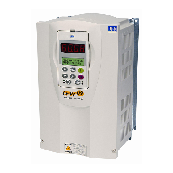
- Page 2 Power Connections and Keypad Operation: The CFW09 Quick Start Guide is a supplement to help get the CFW09 started quickly using the most common installation and configuration options. This CFW09 Quick Start Guide is not meant to replace the CFW09 User’s Manual. For detailed instructions, safety precautions, proper mounting, installation, configuration, and operation please refer to the CFW09 User’s Guide.
- Page 3 PE on the chassis (Refer to Figure 1). Note: Only three-phase AC motors can be used. 4. Apply power to the CFW09 inverter and proceed to “Oriented Start-up”. The inverter will display “P201” on the LED/LCD displays. This is the first parameter in the “Oriented Start-up” mode. Note: New CFW09 inverters are shipped with parameters preset to factory defaults.
- Page 4 (2) If E01 fault occurs during deceleration, increase the deceleration time at P101. (3) Minimum and Maximum speeds are set at P133 and P134 respectively. (4) For a complete description of Parameters and Error codes refer to Chapters 6 and 7 in the CFW09 User’s Guide. Local/Remote Modes (Hand-Off-Auto): In the previous section the inverter was operated from the keypad (Local Mode).
- Page 5 Resetting the inverter can be done by disconnecting and reapplying AC power (power-on reset), by pressing the “O/RESET” key (manual reset), automatic reset, or via digital inputs. For details on Reset and a full list and description of Fault Codes please read Chapter 7 in the CFW09 User’s Guide.
- Page 6 P014 to P017 and P060 to P065 – used to read the last 10 faults. P018 to P021 – used to read analog inputs These are just a few examples of inverter set-up and parameters. Please read the CFW09 User’s Guide for additional information.
Need help?
Do you have a question about the CFW09 and is the answer not in the manual?
Questions and answers