
Related Manuals for WEG CFW300 V1.3X


Summary of Contents for WEG CFW300 V1.3X
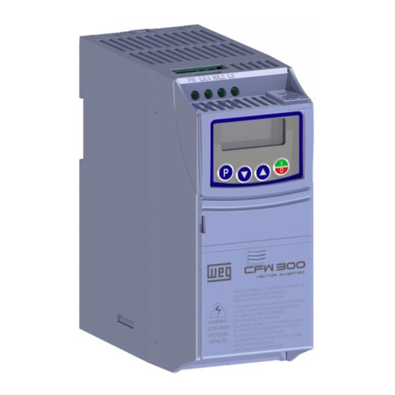
- Page 1 Motors I Automation I Energy I Transmission & Distribution I Coatings Frequency Inverter CFW300 V1.3X Programming Manual...
- Page 3 Programming Manual Series: CFW300 Language: English Document: 10003572354 / 02 Software Version: 1.3X Publication Date: 03/2018...
- Page 4 Summary of Reviews The information below describes the revisions made to this manual. Version Review Description V1.1X First edition General review Version update V1.2X Addition of new parameter: P841 Change of parameters: P402 and P840 General review V1.3X Version update Addition of new parameters: P080, P081, P082, P580, P582...
-
Page 5: Table Of Contents
Contents QUICK REFERENCE OF PARAMETERS, ALARMS AND FAULTS ..0-1 1 SAFETY INSTRUCTIONS ............... 1-1 1.1 SAFETY WARNINGS IN THIS MANUAL ..................1-1 1.2 SAFETY WARNINGS IN THE PRODUCT ..................1-1 1.3 PRELIMINARY RECOMMENDATIONS ..................1-1 2 GENERAL INFORMATION ..............2-1 2.1 ABOUT THE MANUAL ........................2-1 2.2 TERMINOLOGY AND DEFINITIONS....................2-1 2.2.1 Terms and Definitions Used ....................2-1 2.2.2 Numerical Representation .................... - Page 6 Contents 11 FUNCTIONS COMMON TO ALL THE CONTROL MODES ....11-1 11.1 RAMPS ............................11-1 11.2 DC LINK VOLTAGE AND OUTPUT CURRENT LIMITATION .............11-3 11.2.1 DC Link Voltage Limitation by "Ramp Hold" P150 = 0 or 2 ..........11-3 11.2.2 DC Link Voltage Limitation by "Accelerate Ramp" P150 = 1 or 3 .......11-3 11.2.3 Output Current Limitation by "Ramp Hold"...
- Page 7 Contents 17 SOFTPLC ..................... 17-1 18 APPLICATIONS ................... 18-1 18.1 INTRODUCTION .........................18-1 18.2 PID CONTROLLER ........................18-1 18.2.1 Start-Up ........................... 18-3 18.2.2 Academic PID Controller ....................18-5 18.2.3 Parameters ........................18-6 18.2.3.1 Sleep Mode ......................18-17...
- Page 8 Contents...
-
Page 9: Quick Reference Of Parameters, Alarms And Faults
Quick Reference of Parameters, Alarms and Faults QUICK REFERENCE OF PARAMETERS, ALARMS AND FAULTS Param. Description Adjustable Range Factory Setting Prop. Page P000 Access to Parameters 0 to 9999 P001 Speed Reference 0 to 9999 15-1 P002 Output Speed (Motor) 0 to 9999 15-1 P003... - Page 10 Quick Reference of Parameters, Alarms and Faults Param. Description Adjustable Range Factory Setting Prop. Page P029 Power HW Configuration 0 = Non-identified According the 1 = 1.6 A / 110 V inverter model 2 = 2.6 A / 110 V 3 = 4.0 A / 110 V 4 = 6.0 A / 110 V 5 = 1.6 A / 220 V...
- Page 11 2 to 4 = Not Used 5 = V V W P204 Load/Save Parameters 0 to 4 = Not Used 5 = Load WEG 60 Hz 6 = Load WEG 50 Hz 7 = Load User 8 = Not Used 9 = Save User...
- Page 12 Quick Reference of Parameters, Alarms and Faults Param. Description Adjustable Range Factory Setting Prop. Page P220 LOC/REM Selection Source 0 = Always Local 1 = Always Remote 2 and 3 = Not Used 4 = DIx 5 = Serial/USB (LOC) 6 = Serial/USB (REM) 7 and 8 = Not Used 9 = CO/DN/DP (LOC)
- Page 13 Quick Reference of Parameters, Alarms and Faults Param. Description Adjustable Range Factory Setting Prop. Page P231 AI1 Signal Function 0 = Speed Ref. 12-2 1 to 3 = Not Used 4 = PTC 5 and 6 = Not used 7 = SoftPLC 8 = Application Function 1 9 = Application Function 2 10 = Application Function 3...
- Page 14 Quick Reference of Parameters, Alarms and Faults Param. Description Adjustable Range Factory Setting Prop. Page P252 AO1 Output Gain 0.000 to 9.999 1.000 12-8 P253 AO1 Output Signal 0 = 0 to 10 V 12-8 1 = 0 to 20 mA 2 = 4 to 20 mA 3 = 10 to 0 V 4 = 20 to 0 mA...
- Page 15 Quick Reference of Parameters, Alarms and Faults Param. Description Adjustable Range Factory Setting Prop. Page P270 DI8 Input Function See Options in P263 12-12 P271 DIs Signal 0 = All DIx NPN 12-14 1 = (DI1...DI4) PNP 2 = (DI5...DI8) PNP 3 = (DI1...DI8) PNP P275 DO1 Output Function...
- Page 16 Quick Reference of Parameters, Alarms and Faults Param. Description Adjustable Range Factory Setting Prop. Page P304 Skip Frequency 2 0.0 to 400.0 Hz 0.0 Hz 11-10 P306 Skip Band 0.0 to 25.0 Hz 0.0 Hz 11-10 P308 Serial Address 1 to 247 16-1 P310 Serial Baud Rate...
- Page 17 Quick Reference of Parameters, Alarms and Faults Param. Description Adjustable Range Factory Setting Prop. Page P407 Motor Rated Power Factor 0.50 to 0.99 0.69 cfg, V V W 10-5 P408 Run Self-Tuning 0 = No cfg, VVW 10-5 1 = Yes P409 Stator Resistance 0.01 to 99.99 Ω...
- Page 18 Quick Reference of Parameters, Alarms and Faults Param. Description Adjustable Range Factory Setting Prop. Page P684 CO/DN/DP Control 0 to FFFF (hexa) 7-12 (**) Bit 0 = Ramp Enable Bit 1 = General Enable Bit 2 = Run Forward Bit 3 = JOG Enable Bit 4 = Remote Bit 5 = 2 Ramp...
- Page 19 Quick Reference of Parameters, Alarms and Faults Param. Description Adjustable Range Factory Setting Prop. Page P721 CANopen Com. Status 0 = Inactive 16-3 (**) 1 = Reserved 2 = Communic. Enabled 3 = Error Ctrl. Enable 4 = Guarding Error 5 = Heartbeat Error P722 CANopen Node Status...
- Page 20 Quick Reference of Parameters, Alarms and Faults Param. Description Adjustable Range Factory Setting Prop. Page SoftPLC Parameter Configuration for the User's Application (P903 = 0) P910 SoftPLC Parameter 1 -9999 to 9999 17-2 P911 SoftPLC Parameter 2 -9999 to 9999 17-2 P912 SoftPLC Parameter 3...
- Page 21 Quick Reference of Parameters, Alarms and Faults Param. Description Adjustable Range Factory Setting Prop. Page SoftPLC Parameter Configuration for PID Controller Application (P903 = 1) P910 PID Controller Application Version 0.00 to 90.00 18-8 P911 Control Setpoint -9999 to 9999 [SPLC Eng. Un.] 18-8 P912 Control Setpoint 1...
- Page 22 Quick Reference of Parameters, Alarms and Faults Param. Description Adjustable Range Factory Setting Prop. Page P930 Automatic Adjustment of the PID 0 = P911 inactive and P918 18-15 Controller Setpoint inactive 1 = P911 active and P918 inactive 2 = P911 inactive and P918 active 3 = P911 active and P918 active P931 Proportional Gain...
- Page 23 High ambient temperature around the inverter (> 50 °C (> „ 122 °F)) and high output current. For further information, refer to of the user’s manual available for download on the website: www.weg.net. Blocked or defective fan. „ Heatsink is too dirty, preventing the air flow.
- Page 24 High ambient temperature around the inverter (> 50 °C „ (> 122 °F)) and high output current. For further information, refer to of the user's manual available for download on the website: www.weg.net. Blocked or defective fan. „ Heatsink is too dirty, preventing the air flow.
- Page 25 Quick Reference of Parameters, Alarms and Faults Fault / Alarm Description Possible Causes F078 Overtemperature fault measured on the Overload on the motor shaft. „ Motor Overtemperature motor temperature sensor (Triple PTC) Load cycle is too high (high number of starts and stops per „...
- Page 26 Quick Reference of Parameters, Alarms and Faults Fault / Alarm Description Possible Causes F240 It indicates fault in the access to the Check if the Profibus DP module is correctly fitted. „ Profibus DP Module Profibus DP communication module Hardware errors due to improper handling or installation of the „...
-
Page 27: Safety Instructions
Safety Instructions 1 SAFETY INSTRUCTIONS This manual contains the information necessary for the correct setting of the CFW300 frequency inverter. It was developed to be used by people with proper technical training or qualification to operate this kind of equipment. These people must follow the safety instructions defined by local standards. The noncompliance with the safety instructions may result in death risk and/or equipment damage. - Page 28 If necessary, first touch the grounded metallic frame size or use proper grounding strap. Do not execute any applied potential test on the inverter! If necessary, contact WEG. NOTE! Frequency inverters may interfere in other electronic equipments. Observe the recommendations „...
-
Page 29: General Information
General Information 2 GENERAL INFORMATION 2.1 ABOUT THE MANUAL This manual presents information necessary for the configuration of all the functions and parameters of the CFW300 frequency inverter. This manual must be used together with the user’s manual of the CFW300. The text provides additional information so as simplify the use and programming of the CFW300 in certain applications. -
Page 30: Numerical Representation
General Information hp (HP): horse power = 746 Watts (unit of measurement of power, normally used to indicate mechanical power of electric motors). Hz: hertz; unit of measurement of frequency. kHz: kilohertz = 1000 Hertz. mA: miliampere = 0.001 ampere. Nm: Newton meter;... -
Page 31: About The Cfw300
About the CFW300 3 ABOUT THE CFW300 The CFW300 frequency inverter is a high performance product which enables speed and torque control of three- phase induction motors. This product provides the user with the options of vector (VVW) or scalar (V/f) control, both programmable according to the application. - Page 32 About the CFW300 U/T1 V/T2 Motor L1/L RFI Filter Power W/T3 L2/N supply DC Link Single-phase Inverter rectifier capacitor with IGBT bank transistors Preload HMI (remote) Power Control Sources for electronics and interfaces between power and control RS-485 Interfaces (RS- 232, RS-485, Software USB, CANopen,...
- Page 33 About the CFW300 -UD +BR R/L1/L U/T1 Power Filter RFI V/T2 S/L2/N Motor supply Preload T/L3 W/T3 DC Link Inverter Three-phase capacitor with IGBT rectifier bank transistors Braking IGBT HMI (remote) Power Control Sources for electronics and interfaces between power and control RS-485 Interfaces (RS-232, RS-485,...
- Page 34 About the CFW300 Frame size A Frame size B 1 - HMI 2 - mounting supports (for DIN rail mounting) 3 - communication accessory cover 4 - cover of the IO expansion accessory 5 - protection cover of the connection of the IO expansion accessory 6 - fan with mounting support Figure 3.4: Main components of the CFW300 3-4 | CFW300...
-
Page 35: Hmi And Basic Programming
HMI and Basic Programming 4 HMI AND BASIC PROGRAMMING 4.1 USE OF THE HMI TO OPERATE THE INVERTER Using the HMI, it is possible to command the inverter, view and adjust all of its parameters. The HMI presents the following functions: Enables/Disables the inverter via Selects (switches) between acceleration/deceleration ramp... - Page 36 HMI and Basic Programming Start-up Mode It is the initial status of the HMI after the successful power-up (without fault, „ alarms or undervoltages). Monitoring Press the key to go to level 1 of the setting mode - parameter selection. „...
-
Page 37: Programming Basic Instructions
Programming Basic Instructions 5 PROGRAMMING BASIC INSTRUCTIONS NOTE! The inverter comes from the factory with the frequency (V/f 50/60 Hz mode) and voltage adjusted according to the market. The reset to factory default may change the content of the parameters related to frequency. In the detailed description, some parameters have values between brackets, which represents the default value for operation in 50 Hz;... - Page 38 Programming Basic Instructions P200 - Password Adjustable Factory 0 = Inactive Range: Setting: 1 = Active 2 to 9999 = New Password Properties: Description: It allows activating the password (by inserting a new value) or disabling it. For further details regarding the use of this parameter, refer to Table 5.1 on page 5-2.
- Page 39 Programming Basic Instructions Together with the unit in P209 and the decimal places in P210, the rated reference (P208) defines the speed indication on the inverter HMI. According to the factory default of those parameters, the preset scale on the inverter is in "Hz"...
-
Page 40: Backup Parameters
Not Used: no action Load WEG 60 Hz: it loads the default parameters on the inverter with the factory default for 60 Hz Load WEG 50 Hz: it loads the default parameters on the inverter with the factory default for 50 Hz... -
Page 41: Situations For Config Status
Programming Basic Instructions 5.3 SITUATIONS FOR CONFIG STATUS The Config status is indicated by the HMI "ConF" status, as well as in parameters P006 and P680. Such status indicates that the CFW300 cannot enable the output PWM pulses because the inverter configuration is incorrect or incomplete. -
Page 42: Engineering Units For Softplc
Programming Basic Instructions 5.4 ENGINEERING UNITS FOR SOFTPLC This parameter group allows the user to configure the engineering units for indication on the HMI of the user's parameters of the SoftPLC module. P510 - SoftPLC Engineering Unit Adjustable Factory 0 = Without Unit Range: Setting: 1 = A... -
Page 43: Identification Of The Inverter Model And Accessories
Identification of the Inverter Model and Accessories 6 IDENTIFICATION OF THE INVERTER MODEL AND ACCESSORIES In order to check the inverter model, see the code on the product nameplate on the side of the inverter. Once the inverter model identification code is checked, it is necessary to interpret it in order to understand its meaning. - Page 44 Identification of the Inverter Model and Accessories Table 6.1: IO's expansion accessories identified on the CFW300 Name Description P027 No accessories CFW300-IOAR Accessory for IO’s expansion: 1 analog input + 1 analog output + 3 relay digital outputs CFW300-IODR Accessory for IO’s expansion: 4 digital inputs (NPN/PNP) + 3 relay digital outputs CFW300-IOADR Accessory for IO’s expansion: 1 input for infrared receiver + 1 NTC sensor input + 3 relay digital outputs CFW300-IOAENC...
- Page 45 Identification of the Inverter Model and Accessories P295 - Inverter Rated Current Adjustable 1.6 to 15.2 A Factory According Range: Setting: inverter model Properties: Description: This parameter presents the inverter rated current as per Table 6.3 on page 6-2. P296 - Line Rated Voltage Adjustable Factory 0 = Reserved...
- Page 46 Identification of the Inverter Model and Accessories 6-4 | CFW300...
-
Page 47: Logical Command And Frequency Reference
Logical Command and Speed Reference 7 LOGICAL COMMAND AND FREQUENCY REFERENCE The drive of the electric motor connected to the inverter depends on the logical command and on the reference defined by one of the several possible sources, such as: HMI keys, digital inputs (DIx), analog inputs (AIx), Serial/ USB interface, CANopen/DeviceNet interface, SoftPLC, etc. - Page 48 Logical Command and Speed Reference Direction of rotation Run/ Stop Control word Control word Direction of rotation Control word Run/ Stop All the command and reference sources of the Inverter LOC/REM Ramp Reference frequency Reference frequency Reference frequency Figure 7.1: Block diagram for commands and references 7-2 | CFW300...
- Page 49 Logical Command and Speed Reference Command selection frequency P221 or P222 Reference key (P121) 0 - K (via DI1 to 4 - FI P247 DI4) 17 - FI >0 P249 Accel. Decel. 7 - eP AI1 (A) Electronic potentiometer Frequency AI1 (V) reference of 10 V...
- Page 50 Logical Command and Speed Reference P220 - Local/Remote Selection Adjustable 0 = Always Local Factory Range: 1 = Always Remote Setting: 2 and 3 = Not Used 4 = Digital Input (DIx) 5 = Serial/USB (LOC) 6 = Serial/USB (REM) 7 and 8 = Not Used 9 = CO/DN/DP (LOC) 10 = CO/DN/DP (REM)
- Page 51 Logical Command and Speed Reference E.P.: electronic potentiometer; refer to Section 12.5 DIGITAL INPUTS on page 12-11. „ Multispeed: refer to Section 12.5 DIGITAL INPUTS on page 12-11. „ AIx > 0: the negative values of the AIx reference are zeroed. „...
-
Page 52: Frequency Reference
Logical Command and Speed Reference P225 - JOG Selection - LOCAL Situation P228 - JOG Selection - REMOTE Situation Adjustable 0 = Disabled Factory P225 = 1 Range: 1 = Not Used Setting: P228 = 2 2 = DIx 3 = Serial/USB 4 = Not Used 5 = CO/DN/DP 6 = SoftPLC... -
Page 53: Limits For Frequency Reference
Logical Command and Speed Reference 7.2.1 Limits for Frequency Reference Although the parameters to adjust the reference have a wide range of values (0 to 400.0 Hz), the value applied to the ramp is limited by P133 and P134. Therefore, the values in module out of this range will have no effect on the reference. -
Page 54: Parameters For Frequency Reference
Logical Command and Speed Reference 7.2.3 Parameters for Frequency Reference P121 - Frequency Reference via HMI Adjustable 0.0 to 400.0 Hz Factory 3.0 Hz Range: Setting: Properties: Description: Parameter P121 stores the frequency reference via HMI (P221 = 0 or P222 = 0). When the keys active and the HMI in the monitoring mode, the value of P121 is increased and shown on the HMI main display. - Page 55 Logical Command and Speed Reference P128 - Multispeed Reference 5 Adjustable Factory -400.0 to 400.0 Hz 40.0 (30.0) Hz Range: Setting: P129 - Multispeed Reference 6 Adjustable -400.0 to 400.0 Hz Factory 50.0 (40.0) Hz Range: Setting: P130 - Multispeed Reference 7 Adjustable -400.0 to 400.0 Hz Factory...
-
Page 56: Reference Via Electronic Potentiometer
Logical Command and Speed Reference P131 Output frequency P130 P129 P128 Acceleration P127 ramp P126 P125 P124 Time Active DI1 or DI2 Inactive DI5 or DI6 Active Inactive DI3 or DI7 Active DI4 or DI8 Inactive Figure 7.3: Operating graph of the Multispeed function Table 7.3: Multispeed frequency reference 8 Referency 4 Referency... -
Page 57: Frequency Input Fi
Logical Command and Speed Reference DIx - Accelerate Reference Ramp DIx - Decelerate Reset & Enabling (RUN) P133 Output frequency Time Active DIx - Accelerate Inactive Reset Time Active DIx - Decelerate Inactive Time Active DIx - Run/Stop Inactive Time Figure 7.4: Operating graph of the E.P. - Page 58 Logical Command and Speed Reference P680 - Logical Status Adjustable Factory 0 to FFFF (hexa) Range: Setting: Properties: Description: The inverter status word is unique for all the sources and can only be accessed for reading. It indicates all the relevant operating status and modes of the inverter.
-
Page 59: Control Via Hmi Inputs
Logical Command and Speed Reference Table 7.5: Control word Function Description Ramp Enable 0: stops the motor by deceleration ramp 1: spins the motor according to the acceleration ramp until reaching the speed reference value General Enable 0: disables the inverter completely, interrupting the power supply to the motor 1: enables the inverter completely, allowing the operation of the motor Run Forward 0: spins the motor in the opposite direction of the reference signal (reverse) - Page 60 Logical Command and Speed Reference 7-14 | CFW300...
-
Page 61: Available Motor Control Types
Available Motor Control Types 8 AVAILABLE MOTOR CONTROL TYPES The inverter feeds the motor with variable voltage, current and frequency, providing control of the motor speed. The values applied to the motor follow a control strategy, which depends on the selected type of motor control and on the inverter parameter settings. - Page 62 The default setting of P397 meets most application needs of the inverter. Therefore, avoid modifying its content without knowing the related consequences. If you are not sure, contact WEG Technical Assistance before changing P397. Table 8.1: Options available to configure the control (P397)
-
Page 63: Scalar Control
V/f Scalar Control 9 V/f SCALAR CONTROL This is the classical control method for three-phase induction motors, based on a curve that relates output frequency and voltage. The inverter works as a variable frequency and voltage source, generating a combination of voltage and frequency according to the configured curve. - Page 64 V/f Scalar Control Figure 9.1: Block diagram of V/f scale control 9-2 | CFW300...
-
Page 65: Parameterization Of The V/F Scalar Control
V/f Scalar Control 9.1 PARAMETERIZATION OF THE V/f SCALAR CONTROL The scalar control is the inverter factory default control mode for its popularity and because it meets most applications of the market. However, parameter P202 allows the selection of other options for the control mode, as per Chapter 8 AVAILABLE MOTOR CONTROL TYPES on page 8-1. - Page 66 V/f Scalar Control P136 - Manual Torque Boost Adjustable 0.0 to 30.0 % Factory 5.0 % Range: Setting: Properties: Description: It actuates at low speeds, that is, in the range 0 to P146 (V/f) or 0 to P145 (Quadratic V/f), increasing the inverter output voltage so as to compensate the voltage drop in the motor stator resistance in order to keep the torque constant.
- Page 67 V/f Scalar Control P142 - Maximum Output Voltage P143 - Intermediate Output Voltage Adjustable Factory 0.0 to 100.0 % P142 = 100.0 % Range: Setting: P143 = 50.0 % Properties: cfg, V/f Description: These parameters allow adjusting the inverter V/f curve together with its orderly pairs P145 and P146. P145 - Field Weakening Start Frequency P146 - Intermediate Output Frequency Adjustable...
- Page 68 V/f Scalar Control P007 Voltage I x R Frequency reference applied on P136 the motor I x R Output automatic active P137 current P139 Figure 9.6: Block diagram of the automatic torque boost P138 - Slip Compensation Adjustable -10.0 to 10.0 % Factory 0.0 % Range:...
-
Page 69: Start-Up In V/F Mode
V/f Scalar Control 9.2 START-UP IN V/f MODE NOTE! Read chapter 3 Installation and Connection of the CFW300 user manual before installing, energizing or operating the inverter. Sequence for installation, verification, power up and start-up. 1. Install the inverter: according to chapter 3 Installation and Connection of the user’s manual, making all the power and control connections. - Page 70 V/f Scalar Control P401 - Motor Rated Current Adjustable 0.0 to 40.0 A Factory 1.0 x I Range: Setting: Properties: Description: In order to obtain the proper operation of the energy saving function, the motor current value must be correctly set, according to the information on the motor nameplate.
- Page 71 V/f Scalar Control P590 – Energy Saving Minimum Frequency Adjustable 12.0 to 400.0 Hz Factory 20 Hz Range: Setting: Properties: cfg, V/f Description: This parameter defines the minimum speed value at which the energy saving function will remain active. The hysteresis for the minimum speed level is of 2 Hz. P591 –...
- Page 72 V/f Scalar Control 9-10 | CFW300...
-
Page 73: V W Vector Control
10 V V W VECTOR CONTROL The V V W vector control mode (Voltage Vector WEG) uses a control method with a much higher performance than the V/f control because of the load torque estimation and of the control of the magnetic flux in the air gap, as per scheme of Figure 10.1 on page... - Page 74 V V W Vector Control Figure 10.1: V V W control flow 10-2 | CFW300...
-
Page 75: Vvw Vector Control Parameterization
Below are described the parameters to configure the V V W vector control setting. This data is easily obtained on WEG standard motor nameplates, however in older motors or motors made by other manufacturers, the data may not be readily available. In those cases, it is recommended first contact the motor manufacturer, measure or calculate the desired parameter. - Page 76 V V W Vector Control P399 - Motor Rated Efficiency Adjustable 50.0 to 99.9 % Factory 67.0 % Range: Setting: Properties: cfg, V V W Description: This parameter is important for the precise operation of the V V W control. A misconfiguration will cause incorrect calculation of the slip compensation, reducing the performance of the speed control.
- Page 77 V V W Vector Control P404 - Motor Rated Power Adjustable 0 = 0.16 HP (0.12 kW) Factory According Range: 1 = 0.25 HP (0.18 kW) Setting: inverter 2 = 0.33 HP (0.25 kW) model 3 = 0.50 HP (0.37 kW) 4 = 0.75 HP (0.55 kW) 5 = 1.00 HP (0.75 kW) 6 = 1.50 HP (1.10 kW)
-
Page 78: Start-Up In V V W Mode
5. Activation of the V V W control: set P202 = 5 and parameters P399, P400, P401, P402, P403, P404 and P407 according to the motor nameplate. Also set the value of P409. If some of those data are not available, enter the approximate value by calculation or by similarity with WEG standard motor - see Table 10.1 on page 10-3. - Page 79 V V W Vector Control 7. End of the Self-Tuning: at end of the self-tuning, the HMI returns to the browsing menu, the bar displays the parameter programmed by P207 again and the stator resistance measured is stored in P409. On the other hand, if the self-tuning fails, the inverter will indicate a fault.
- Page 80 V V W Vector Control 10-8 | CFW300...
-
Page 81: Functions Common To All The Control Modes
Functions Common to All the Control Modes 11 FUNCTIONS COMMON TO ALL THE CONTROL MODES This chapter describes the functions common to the inverter V/f and V V W control modes, but which interferes in the drive performance. 11.1 RAMPS The inverter ramp functions allow the motor to accelerate or decelerate faster or slower. - Page 82 Functions Common to All the Control Modes P103 - Deceleration Time 2 Ramp Adjustable 0.1 to 999.9 s Factory 10.0 s Range: Setting: Properties: Description: Deceleration time from maximum frequency (P134) to zero when the 2 Ramp is active. P106 - Emergency Ramp Acceleration Time Adjustable Factory 0.1 to 999.9 s...
-
Page 83: Dc Link Voltage And Output Current Limitation
Functions Common to All the Control Modes P105 - 1 Ramp Selection Adjustable 0 = 1 Ramp Factory Range: 1 = 2 Ramp Setting: 2 = DIx 3 = Serial/USB 4 = Reserved 5 = CO/DN/DP 6 = SoftPLC Properties: Description: It defines the origin source of the command to select between the first and second Ramp. - Page 84 Functions Common to All the Control Modes P149 - Compensation of the DC Link Voltage Adjustable Factory 0 = Inactive Range: Setting: 1 = Active Properties: Description: It enables the use of Compensation of the DC link. P150 - Type DC V/f Link Regulator Adjustable 0 = Hold_Ud and Decel_LC Factory...
-
Page 85: Output Current Limitation By "Ramp Hold" P150 = 2 Or 3
Functions Common to All the Control Modes DC Link voltage (P004) F022-overvoltage P151 DC Link regulation rated Time Output frequency Time Figure 11.3: Example graph of DC Link voltage limitation - Ramp Hold DC Link voltage (P004) F022-overvoltage P151 DC Link regulation rated Time Output... -
Page 86: Current Limitation Type "Decelerate Ramp" P150 = 0 Or 1
Functions Common to All the Control Modes 11.2.4 Current Limitation Type "Decelerate Ramp" P150 = 0 or 1 It prevents the motor from collapsing during torque overload in the acceleration or constant frequency. „ Actuation: if the motor current exceeds the value set in P135, a null value is forced for the frequency ramp input „... -
Page 87: Flying Start / Ride-Through
Functions Common to All the Control Modes 11.3 FLYING START / RIDE-THROUGH The Flying Start function allows driving a motor that is in free running, accelerating it from the rotation in which it is. The Ride-Through function allows recovering the inverter, with no locking by undervoltage, when there is an instant drop in the power supply. -
Page 88: Ride-Through Function
Functions Common to All the Control Modes 11.3.2 Ride-Through Function The Ride-Through function will disable the inverter output pulses (IGBT) as soon as the supply voltage reaches a value below the undervoltage value. A fault due to undervoltage (F021) does not occur and the DC link voltage will slowly drop until the supply voltage returns. - Page 89 Functions Common to All the Control Modes Direct current injection at start Output frequency Time P299 P302 DC braking Time Stop Figure 11.7: DC Braking actuation at start P300 - DC Braking Time at Stop Adjustable 0.0 to 15.0 s Factory 0.0 s Range:...
-
Page 90: Skip Frequency
Functions Common to All the Control Modes P301 - Frequency to Begin DC Braking at Stop Adjustable 0.0 to 400.0 Hz Factory 3.0 Hz Range: Setting: Properties: Description: This parameter establishes the initial point to apply the DC Braking at the stop when the inverter is disabled by ramp, as per Figure 11.8 on page 11-9. -
Page 91: Fire Mode
It is essential to follow the aforementioned instructions before using the CFW300 in the "Fire „ Mode" function. Under no circumstance shall WEG take any liability for deaths, damages, compensations and/or losses occurred due to the improper programming or operation of the CFW300 in the "Fire Mode" function. IMPORTANT – RISK OF DEATH! When activating the “Fire Mode”... - Page 92 Functions Common to All the Control Modes NOTE! When activating the "Fire Mode" function, the user acknowledges that the protection functions of the CFW300 are disabled, which may result in damages to the CFW300, to the components connected to it, to the environment in which it is installed and to the people present in such environment. Therefore, the user takes full liability for the resulting risks.
-
Page 93: Digital And Analog Inputs And Outputs
Digital and Analog Inputs and Outputs 12 DIGITAL AND ANALOG INPUTS AND OUTPUTS This section presents the parameters to configure the CFW300 inputs and outputs. This configuration depends on the accessory, as per Table 12.1 on page 12-1. Table 12.1: I/O configurations of the CFW300 Functions Accessory Supply 5 V Supply 10 V... - Page 94 Digital and Analog Inputs and Outputs If the parameter is set as Active (P230 = 1), the signal in the analog inputs will have a dead zone, where the frequency reference remains at the Minimum frequency value (P133), even with the variation of the input signal. Check Figure 12.1 on page 12-2.
- Page 95 Digital and Analog Inputs and Outputs Description: These parameters define the analog inputs functions. When the 0 option is selected (Reference Frequency), the analog inputs can provide the reference for the motor, subject to the specified limits (P133 and P134) and to the action of the ramps (P100 to P103). However, in order to do so, it is also necessary to configure parameters P221 and/or P222, by selecting the use of the desired analog input.
- Page 96 Digital and Analog Inputs and Outputs Description: Each analog input of the inverter is defined by the steps of calculation of Signal, Offset, Gain, Filter, Function and Value AIx, as shown in Figure 12.2 on page 12-4. Input AI1 - P018 AI2 - P019 Filter Signal...
-
Page 97: Ntc Sensor Input
Digital and Analog Inputs and Outputs For example: AIx = 5 V, offset = -70.0 %, gain = 1.000, with signal of 0 to 10 V, that is, AIx = 0 and AIx = 10. AIx(%) = x (100 %) + (-70 %) x 1 = -20.0 % Another example: AIx = 12 mA, offset = -80.0 %, gain = 1.000, with signal of 4 to 20 mA, that is, AIx = 4 and = 16. -
Page 98: Analog Output
Digital and Analog Inputs and Outputs 12.3 ANALOG OUTPUT The analog output (AOx) is configured by means of three types of parameters: Function, Gain and Signal, according to the block diagram below. The quantity of analog outputs depends on the expansion accessory IO's. For further details, refer to the installation, configuration and operation guide of the IO's expansion accessory used. - Page 99 Digital and Analog Inputs and Outputs P251 - AO1 Function P254 - AO2 Function Adjustable 0 = Speed Ref. Factory P251 = 2 Range: 1 = Not Used Setting: P254 = 5 2 = Real Speed 3 and 4 = Not Used 5 = Output Current 6 = Not Used 7 = Active Current...
- Page 100 Digital and Analog Inputs and Outputs P252 - AO1 Gain P255 - AO2 Gain Adjustable 0.000 to 9.999 Factory 1.000 Range: Setting: Properties: Description: It determines the analog outputs gain according to the equations of Table 12.4 on page 12-8. P253 - AO1 Signal P256 - AO2 Signal Adjustable...
-
Page 101: Frequency Input
Digital and Analog Inputs and Outputs 12.4 FREQUENCY INPUT A frequency input consists of a fast digital input able to convert the frequency of the pulses in the input into a proportional signal with 15-bit resolution. After the conversion, this signal is used as an analog signal for frequency reference, process variable, for example. - Page 102 Digital and Analog Inputs and Outputs P246 - Frequency Input FI Adjustable 0 = Inactive Factory Range: 1 = Active in DI1 Setting: 2 = Active in DI2 3 = Active in DI3 4 = Active in DI4 Properties: Description: When set to "0"...
-
Page 103: Digital Inputs
Digital and Analog Inputs and Outputs The value FI = -20.0 % means that the motor will run in the opposite direction with a reference in module equal 20.0 % of P134, with the function of the FI signal for "Frequency Reference" (P221 = 4). When P246 = 3, the digital input DI3 is defined for frequency input, regardless the value of P265, with operating capacity in the band from 0 to 3000 Hz in 10 Vpp. - Page 104 Digital and Analog Inputs and Outputs P263 - Function of Digital Input DI1 P264 - Function of Digital Input DI2 P265 - Function of Digital Input DI3 P266 - Function of Digital Input DI4 P267 - Function of Digital Input DI5 P268 - Function of Digital Input DI6 P269 - Function of Digital Input DI7 P270 - Function of Digital Input DI8...
- Page 105 Digital and Analog Inputs and Outputs Table 12.6: Digital input functions Value Description Dependence Not used Run/Stop command P224 = 1 or P227 = 1 General Enable command Fast Stop P224 = 1 or P227 = 1 (P224 = 1 and P223 = 4) or Forward run command (P227 = 1 and P226 = 4) Reverse run command...
- Page 106 Digital and Analog Inputs and Outputs P271 - Digital Input Signal Adjustable 0 = All DIx NPN Factory Range: 1 = (DI1...DI4) - PNP Setting: 2 = (DI5...DI8) - PNP 3 = (DI1...DI8) - PNP Properties: Description: It configures the default for the digital input signal, that is, NPN and the digital input is activated with 0 V, PNP and the digital input is activated with +24 V.
- Page 107 Digital and Analog Inputs and Outputs d) FORWARD/REVERSE COMMAND This function is the combination of two DIS: one programmed for forward run and the other for reverse run. Active DIx - Forward Inactive Time Active Inactive DIx - Reverse Time Output Forward frequency...
- Page 108 Digital and Analog Inputs and Outputs f) DIRECTION OF ROTATION If the DIx is Inactive, the Direction of Rotation is Forward, otherwise, the direction of rotation will be REVERSE. Forward Output frequency Time Reverse Active Inactive Time Figure 12.10: Example of the Direction of Rotation function g) LOCAL / REMOTO If DIx is inactive, the Local command is selected, reverse the Remote command is selected.
- Page 109 Digital and Analog Inputs and Outputs i) ELECTRONIC POTENTIOMETER (E.P.) The E.P. function enables the setting of the speed via digital inputs programmed for Accelerate E.P. and Decelerate E.P. The basic principle of this function is similar to the sound volume and intensity control of electronic appliances. The operation of the E.P.
- Page 110 Digital and Analog Inputs and Outputs k) 2 RAMP If DIx is inactive, the inverter uses the default ramp by P100 and P101, otherwise, it will use the 2 Ramp by P102 and P103. Active DIx - Run/Stop Inactive Time Active DIx - 2 ramp...
- Page 111 Digital and Analog Inputs and Outputs P134 (Fmax) P133 P133 (Fmin) (Fmin) Output frequency Time Active Pulse DIx - Accelerate/ Turn Turn ON Inactive Time Active Pulse DIx - Decelerate/ Turn Turn OFF Inactive Time Figure 12.14: Example of the Accelerate Turn ON / Decelerate Turn OFF r) STOP Only on pulse in the Dix disables the inverter.
-
Page 112: Input For Infrared Receiver
Digital and Analog Inputs and Outputs 12.6 INPUT FOR INFRARED RECEIVER The CFW300-IOADR accessory uses an infrared remote control to control the inverter. The RC-5 protocol (Philips) was used for the communication of the control with the accessory. The information on the control/selection of remote control is available in the parameters below. - Page 113 Digital and Analog Inputs and Outputs P275 - DO1 Output Function P276 - DO2 Output Function P277 - DO3 Output Function P278 - DO4 Output Function Adjustable Factory 0 to 47 P275 = 13 Range: Setting: P276 = 0 P276 = 0 P278 = 0 Properties: Description:...
- Page 114 Digital and Analog Inputs and Outputs Table 12.7: Digital Output Functions Value Function Description Not used It deactivates the digital output F* ≥ Fx Active when the frequency reference F* (P001) is greater or iqual the Fx (P281) F ≥ Fx Active when the Output Frequency F (P002) is greater or iqual the Fx (P281) F ≤...
- Page 115 Digital and Analog Inputs and Outputs P281 - Frequency Fx Adjustable 0.0 to 400.0 Hz Factory 3.0 Hz Range: Setting: P282 - Hysteresis Fx Adjustable 0.0 to 15.0 Hz Factory 0.5 Hz Range: Setting: Properties: Description: These parameters set the hysteresis and actuation level on the Fx output frequency signal and on the F* ramp input of the relay digital output.
- Page 116 Digital and Analog Inputs and Outputs 12-24 | CFW300...
-
Page 117: Dynamic Braking
Dynamic Braking 13 DYNAMIC BRAKING The braking torque that can be obtained through the application of frequency inverters without dynamic braking resistors varies from 10 % to 35 % of the motor rated torque. In order to obtain higher braking torques, resistors for dynamic braking are used. In this case the regenerated energy is dissipated on the resistor mounted externally to the inverter. - Page 118 Dynamic Braking DC Link Voltage (U ) (P004) F022 - overvoltage P0153 Dynamic braking actuation Rated U Time Braking resistor voltage (DB) Time Figure 13.1: Dynamic Braking actuation curve Steps to enable the Dynamic Braking. Connect the braking resistor. Refer to item 3.2.3.2 Dynamic Braking of the CFW300 user's manual. „...
-
Page 119: Faults And Alarms
Faults and Alarms 14 FAULTS AND ALARMS The problem detection structure in the inverter is based on the fault and alarm indication. In case of fault, the locking the IGBTs and motor stop by inertia will occur. The alarm works as a warning for the user of critical operating conditions and that may cause a fault if the situation is not corrected. - Page 120 Faults and Alarms P037 - Motor Overload Ixt Adjustable 0.0 to 100.0 % Factory Range: Setting: Properties: Description: It indicates the present motor overload percentage or overload intergrator level. When this parameter reaches 6.3 %, the inverter will indicate the motor overload alarm (A046). Or when this parameter reaches 100 %, the "Motor Overload"...
-
Page 121: Igbts Overload Protection (F051 And A050)
The default setting of P397 meets most application needs of the inverter. Therefore, avoid modifying its content without knowing the related consequences. If you are not sure, contact WEG Technical Assistance before changing P397. P352 - Fan Control Configuration Adjustable... -
Page 122: Overcurrent Protection (F070)
Faults and Alarms The analog input reads the PTC resistance and compares it to the limits for the fault. When those values are exceeded, fault F078 is indicated. As shown in Table 14.3 on page 14-4. Table 14.3: Actuation levels of fault F078 PTC Resistance Overtemperature <... -
Page 123: Remote Hmi Communication Error Fault (F701)
NOTE! When this fault occurs, contact WEG. 14.10 FAULT IN THE CPU (F080) The execution of the inverter firmware is monitored at several levels of the firmware internal structure. When some internal fault is detected in the execution, the inverter will indicate F080. -
Page 124: Fault History
Faults and Alarms 14.15 FAULT HISTORY The inverter is able to store a set of data on the last three faults occurred, such as: fault number, current (P003), DC link voltage (P004), output frequency (P005), power module temperature (P030). P048 - Present Alarm P049 - Present Fault Adjustable 0 to 999... -
Page 125: Fault Control
Faults and Alarms P052 - Last Fault DC Link Adjustable 0 to 524 V Factory Range: Setting: Properties: Description: It indicates the DC link voltage at the moment of the last occurred fault. P053 - Output Frequency Last Fault Adjustable Factory 0.0 to 400.0 Hz Range:... - Page 126 Faults and Alarms P358 - Encoder Fault Configuraton Adjustable 0 = Off Factory Range: 1 = F067 ON Setting: 2 = F079 ON 3 = F067, F079 ON Properties: Description: This parameter allows individually disabling the fault detection by software: a) F067 - Inverted Encoder/Motor Wiring and b) F079 - Encoder Signal Fault.
-
Page 127: Reading Parameters
Reading Parameters 15 READING PARAMETERS It is important to point out that all the parameters of this group can only be viewed on the HMI display, and cannot be changed by the user. P001 - Speed Reference Adjustable 0 to 9999 Factory Range: Setting:... - Page 128 Reading Parameters P006 - Inverter Status Adjustable According to Table 15.1 on page 15-2 Factory Range: Setting: Properties: Description: It indicates one of the possible inverter status. The following table contains the description of each state, as well as the indication on the HMI. Table 15.1: Inverter status- P006 P006 Status...
- Page 129 Reading Parameters P009 - Motor Torque Adjustable -200.0 to 200.0 % Factory Range: Setting: Properties: ro, V V W Description: It indicates the torque developed by the motor in relation to the rated torque. P011 – Output Cos ϕ Adjustable Factory -1.00 to 1.00 Range:...
- Page 130 Reading Parameters P029 - Power Hardware Configuration Refer to Section 6.1 INVERTER DATA on page 6-1. P030 - Power Module Temperature Adjustable 0.0 to 200.0 ºC (32 °F to 392 °F) Factory Range: Setting: Properties: Description: Temperature in ºC measured inside the power module by the internal NTC. P037 - Motor Overload Ixt Refer to Section 14.1 MOTOR OVERLOAD PROTECTION (F072 AND A046) on page...
- Page 131 Reading Parameters P047 - CONFIG Status Adjustable 0 to 999 Factory Range: Setting: Properties: Description: This parameter shows the origin situation of CONFIG mode. Refer to Section 5.3 SITUATIONS FOR CONFIG STATUS on page 5-5. CFW300 | 15-5...
- Page 132 Reading Parameters 15-6 | CFW300...
-
Page 133: Communication
Description: These parameters are used for configuration and operation of the RS-232, RS-485, USB and Bluetooth. For a detailed description, refer to the Modbus RTU, user’s manual, available for download on the website: www.weg.net. P770 - Bluetooth Local Name Adjustable... -
Page 134: Can - Canopen / Devicenet Interface
Communication P771 - Bluetooth Parity Password Adjustable 0 to 9999 Factory 1234 Range: Setting: Properties: Description: This parameter defines the bluetooth parity password. This password is limited to the four digits available on the inverter display. It is recommended that the user change this password. NOTE! Parameter P771 is only available with the bluetooth accessory connected. -
Page 135: Profibus Dp Interface
Description: Parameters for configuration and operation of the CAN interface. For detailed description, refer to the CANopen communication manual or DeviceNet communication manual available for download on the website: www.weg.net. 16.3 PROFIBUS DP INTERFACE P740 - Profibus Com. Status P742 - Profibus Reading #3... -
Page 136: Commands And Communication Status
Parameters used for monitoring and controlling the CFW300 inverter by using the communication interfaces. For detailed description, refer to the communication manual (User) according to the interface used. These manuals are they are available for download on the website: www.weg.net. 16-4 | CFW300... -
Page 137: Softplc
SoftPLC 17 SOFTPLC The SoftPLC function allows the inverter to assume PLC (Programmable Logical Controller). For further details regarding the programming of those functions in the CFW300, refer to the "Help" menu of the WPS software. Below are described the parameters related to the SoftPLC. P900 - SoftPLC Status Adjustable 0 = No Application... - Page 138 SoftPLC Figure 17.1: Description of the parameter P903 options P903 Description It defines that the application that will run on the SoftPLC is the one loaded by the user through the ladder programming tool It defines that the application that will run on the SoftPLC is the PID controller ATTENTION! It is recommended to load the factory setting (P204 = 5 or 6) after alternating between user's application and PID controller application.
-
Page 139: Applications
SoftPLC 18 APPLICATIONS 18.1 INTRODUCTION Using the SoftPLC function of the CFW300, it is possible to develop an application (or functionality) in ladder language and include it in the CFW300 inverter software. Parameter P903 allows selecting the application and uploading it to the SoftPLC execution area of the CFW300. The CFW300 has the following application already implanted: PID controller „... - Page 140 SoftPLC In order to enable the operation of the PID controller application, it is necessary to program the speed reference for the SoftPLC function, that is, parameter P221 or P222 in 12 = SoftPLC, and select the PID controller control action in P928 for direct action (=1) or reverse action (=2), thus enabling the PID operation.
-
Page 141: Start-Up
SoftPLC 18.2.1 Start-Up See below the required steps to put the PID controller application into operation. NOTE! For the PID controller application to work properly, it essential to check if the CFW300 is configured properly to drive the motor at the desired speed. In order to do so, check the following settings: Acceleration and deceleration ramps (P100 to P101). - Page 142 SoftPLC Table 18.2: Programming sequence of the PID controller application on the CFW300 Indication on the Seq. Action / Result Display It selects the PID controller application in the SoftPLC function of the CFW300 P903 = 1 It enables the execution of the PID controller application P901 = 1 It selects the PID controller control action, thus enabling its operation and uploading, at this moment, P928 = 1...
-
Page 143: Academic Pid Controller
SoftPLC Table 18.3: Suggestions for the PID controller gain settings Gains Quantity Sampling Time P934 Proportional P931 Integral P932 Derivative P933 Pressure in pneumatic system 0.10 s 1.00 5.00 0.00 Flow in pneumatic system 0.10 s 1.00 5.00 0.00 Pressure in hydraulic system 0.10 s 1.00 5.00... -
Page 144: Parameters
SoftPLC Where: y(k): present output of the PID controller; it may vary from 0.0 to 100.0 %. i(k-1): integral value in the previous state of the PID controller. Kp: Proportional gain = P931. Ki: Integral gain = P932 = [1 / Ti (s)]. Kd: Differential gain = P933 = [Td (s)]. - Page 145 SoftPLC P252 – AO1 Gain P253 – AO1 Signal P254 – AO2 Function P255 – AO2 Gain P256 – AO2 Signal P263 – DI1 Function P264 – DI2 Function P265 – DI3 Function P266 – DI4 Function P275 – DO1 Function (RL1) P276 –...
- Page 146 SoftPLC P910 – PID Controller Application Version Faixa de 0.00 to 90.00 Factory Valores: Setting: Propriedades: Description: Read-only parameter which presents the software version of the PID controller application developed for the SoftPLC function of the CFW300. P911 – Control Setpoint Adjustable Factory -99.99 a 99.99 [Eng.
- Page 147 SoftPLC NOTE! These parameters will be viewed according to the selection of the parameters for the SoftPLC engineering unit (P510 and P511). P916 – PID Controller Process Variable Adjustable -99.99 a 99.99 [SoftPLC Eng. Un.] Factory Range: Setting: Properties: Description: Read-only parameter which presents the value of the PID controller process variable according to the source defined in P921 and scale defined in P922 and P923.
- Page 148 SoftPLC Table 18.5: Description of the logical status of the PID controller application Bits 15 14 13 12 11 10 9 8 7 6 Process Process Process Process PID controller Sleep Mode Function Reserved Variable High Variable High Variable Low Variable Low in Manual or Active (A750)
- Page 149 SoftPLC Table 18.6: Description of the control setpoint source P920 Description It defines that the control setpoint source in automatic mode of the PID controller will be the value programmed in parameter P911 via HMI of the CFW300 frequency inverter or written via communication networks It defines that the control setpoint source in automatic mode of the PID controller will be the value read by the analog input AI1.
- Page 150 SoftPLC P921 – Selection of the Source for the PID Controller Process Variable Adjustable 1 = Process Variable via Analog Input AI1 Factory Range: 2 = Process Variable via Analog Input AI2 Setting: 3 = Process Variable via Difference between AI1 and AI2 Properties: Description: This parameter defines the source of the PID controller process variable.
- Page 151 SoftPLC P924 – Value for Low Level Alarm for the Control Process Variable Adjustable -99.99 a 99.99 [SoftPLC Eng. Un.] Factory 1.00 Range: Setting: Properties: Description: This parameter defines the value below which the low level alarm will be generated for the control process variable (A760).
- Page 152 SoftPLC P927 – Time for Low Level Fault for the Control Process Variable (F763) Adjustable 0.0 to 999.9 s Factory 0.0 s Range: Setting: Properties: Description: This parameter defines how long the high level alarm condition should remain so that the control process variable (A762) will generate fault “F763: High Level Fault of the Control Process Variable”.
- Page 153 SoftPLC P929 – PID Controller Operation Mode Adjustable 0 = Manual Factory Range: 1 = Automatic Setting: 2 = Control Selection to Manual (0) or Automatic (1) via digital input Properties: Description: This parameter defines the operation mode of the CFW300 PID controller. Table 18.10: Description of the PID controller operation mode P928 Description...
- Page 154 SoftPLC Table 18.11: Description of the PID controller setpoint automatic adjustment P930 Description It defines that, in the transition of the PID controller operation mode from manual to automatic, the control setpoint value (P911) will not be uploaded with the present value of the control process variable (P916), and, in the transition of the PID controller operation mode from automatic to manual, the setpoint value of the PID controller in manual mode (P918) will not be uploaded with the present value of the motor speed (P002) It defines that, in the transition of the PID controller operation mode from manual to automatic, the control setpoint value (P911)
-
Page 155: Sleep Mode
SoftPLC P935 – Filter for the PID Controller Control Setpoint Adjustable 0.000 to 9.999 s Factory 0.150 Range: Setting: Properties: Description: This parameter configures the time constant of the 1st order filter to be applied to the PID controller control setpoint, and it is intended to reduce sudden changes in the control setpoint value of the PID controller. - Page 156 SoftPLC P937 – Time to Wake Up Adjustable 0.0 to 999.9 s Factory 5.0 s Range: Setting: Properties: Description: This parameter defines the time the wake up mode active condition should remain to start the motor and control the system. The control process variable must remain smaller (direct PID) or greater (reverse PID) than the deviation defined in P936 for the time set in P937 for the motor to be started and its speed controlled.
- Page 157 SoftPLC COMANDS - DIGITAL INPUTS DI1 - run/stop PROCESS VARIABLE P911 - control setpoint P936 - process variable deviation to wake up P937 - time to wake up MOTOR SPEED (Hz) P134 - maximum speed reference P939 - time to activate the sleep mode P938 - motor speed to activate the sleep mode P133 - minimum speed reference...
Need help?
Do you have a question about the CFW300 V1.3X and is the answer not in the manual?
Questions and answers