
Related Manuals for Tektronix TDS3012C


Summary of Contents for Tektronix TDS3012C
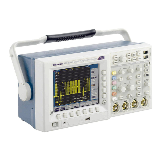
- Page 1 TDS3000C Series Digital Phosphor Oscilloscopes User Manual *P071230807* 071-2308-07...
- Page 3 TDS3000C Series Digital Phosphor Oscilloscopes User Manual Last Published: May 7, 2015 REPRODUCTION AND DISTRIBUTION OF THIS TECHNICAL MANUAL IS AUTHORIZED FOR UNITED STATES OF AMERICA GOVERNMENT PURPOSES. www.tektronix.com 071-2308-07...
- Page 4 Copyright © Tektronix. All rights reserved. Licensed software products are owned by Tektronix or its subsidiaries or suppliers, and are protected by national copyright laws and international treaty provisions. Tektronix products are covered by U.S. and foreign patents, issued and pending.
- Page 5 Tektronix, shipping charges prepaid, and with a copy of customer proof of purchase. Tektronix shall pay for the return of the product to Customer if the shipment is to a location within the country in which the Tektronix service center is located.
-
Page 7: Table Of Contents
Table of Contents Important safety information ......... . . General safety summary . - Page 8 Table of Contents Hard Copy ............Horizontal Controls .
- Page 9 Table of Contents Ethernet Error Messages ......... Ethernet Settings Form.
-
Page 10: Important Safety Information
Important safety information Important safety information This manual contains information and warnings that must be followed by the user for safe operation and to keep the product in a safe condition. To safely perform service on this product, additional information is provided at the end of this section. - Page 11 Use only insulated voltage probes, test leads, and adapters supplied with the product, or indicated by Tektronix to be suitable for the product. Observe all terminal ratings. To avoid fire or shock hazard, observe all ratings and markings on the product.
- Page 12 Important safety information Avoid exposed circuitry. Do not touch exposed connections and components when power is present. Do not operate with suspected failures. If you suspect that there is damage to this product, have it inspected by qualified service personnel. Disable the product if it is damaged.
- Page 13 Important safety information Avoid improper or prolonged use of keyboards, pointers, and button pads. Improper or prolonged keyboard or pointer use may result in serious injury. Be sure your work area meets applicable ergonomic standards. Consult with an ergonomics professional to avoid stress injuries. Probes and test leads Before connecting probes or test leads, connect the power cord from the power connector to a properly grounded power outlet.
-
Page 14: Service Safety Summary
Important safety information Connect and disconnect properly. De-energize the circuit under test before connecting or disconnecting the current probe. Connect the probe reference lead to earth ground only. Do not connect a current probe to any wire that carries voltages above the current probe voltage rating. -
Page 15: Terms In This Manual
Important safety information Verify safety after repair. Always recheck ground continuity and mains dielectric strength after performing a repair. Terms in this manual These terms may appear in this manual: WARNING. Warning statements identify conditions or practices that could result in injury or loss of life. CAUTION. - Page 16 Important safety information TDS3000C Series Oscilloscope User Manual...
-
Page 17: Compliance Information
IEC 61000-4-6:2003. Conducted RF immunity IEC 61000-4-11:2004. Voltage dips and interruptions immunity EN 61000-3-2:2006. AC power line harmonic emissions EN 61000-3-3:1995. Voltage changes, fluctuations, and flicker European contact. Tektronix UK, Ltd. Western Peninsula Western Road Bracknell, RG12 1RF TDS3000C Series Oscilloscope User Manual... - Page 18 Compliance information United Kingdom This product is intended for use in nonresidential areas only. Use in residential areas may cause electromagnetic interference. Emissions which exceed the levels required by this standard may occur when this equipment is connected to a test object. For compliance with the EMC standards listed here, high quality shielded interface cables should be used.
-
Page 19: Safety Compliance
Compliance information Safety compliance This section lists the safety standards with which the product complies and other safety compliance information. EU declaration of conformity – low voltage Compliance was demonstrated to the following specification as listed in the Official Journal of the European Union: Low Voltage Directive 2006/95/EC. - Page 20 Compliance information Additional compliances IEC 61010-1. Safety Requirements for Electrical Equipment for Measurement, Control, and Laboratory Use – Part 1: General Requirements. IEC 61010-2-030. Safety Requirements for Electrical Equipment for Measurement, Control, and Laboratory Use – Part 2-030: Particular requirements for testing and measuring circuits. Equipment type Test and measuring equipment.
- Page 21 Compliance information Pollution degree rating Pollution degree 2 (as defined in IEC 61010-1). Rated for indoor, dry location use only. IP rating IP20 (as defined in IEC 60529). Measurement and overvoltage category descriptions Measurement terminals on this product may be rated for measuring mains voltages from one or more of the following categories (see specific ratings marked on the product and in the manual).
-
Page 22: Environmental Considerations
Directives 2002/96/EC and 2006/66/EC on waste electrical and electronic equipment (WEEE) and batteries. For information about recycling options, check the Support/Service section of the Tektronix Web site (www.tektronix.com). Battery Recycling. This product might contain an optional lithium ion (Li-ion) rechargeable battery, which must be recycled or disposed of properly. - Page 23 The capacity of the optional lithium ion battery pack is under 100 Wh. The battery meets the applicable requirements of UN Manual of Tests and Criteria Part III Section 38.3. As shipped from Tektronix, the battery quantity is under the limit for shipment according to Section II of the relevant Packing Instructions from the IATA Dangerous Goods Regulations.
- Page 24 Compliance information xviii TDS3000C Series Oscilloscope User Manual...
-
Page 25: Preface
Preface This manual contains operating information for the TDS3000C Series Digital Storage Oscilloscopes. The manual consists of the following chapters: The Getting Started chapter briefly describes features of the oscilloscope and provides installation instructions. The Application Examples chapter provides examples on how to solve a variety of measurement problems. - Page 26 Preface Preventing Electrostatic Damage CAUTION. Electrostatic discharge (ESD) can damage components in the oscilloscope and its accessories. To prevent, ESD, observe these precautions when directed to do so. Use a Ground Strap. Wear a grounded, antistatic wrist strap to discharge the static voltage from your body while installing or removing sensitive components.
- Page 27 Internet and a USB flash drive to update your oscilloscope. To update the firmware, follow these steps: From your computer, access the www.tektronix.com Web site and check if a newer version of oscilloscope firmware is available. If there is a newer version of firmware, download the firmware file from the web page.
- Page 28 Preface xxii TDS3000C Series Oscilloscope User Manual...
-
Page 29: Getting Started
Getting Started In addition to a product and feature description, this chapter covers the following topics: How to perform a quick functional check, install and compensate passive probes, compensate the signal path, and set the time and date How to install the power cord, battery pack, and operate the oscilloscope safely with battery power How to install application modules and the communication module How to use the menu system... -
Page 30: Functional Check
Getting Started Functional Check Perform this quick functional check to verify that your oscilloscope is operating correctly. Connect the oscilloscope power cable. (See page 10.) Power on the oscilloscope. Wait for the confirmation that all self tests have passed. Connect the oscilloscope probe to Probe Comp channel 1. - Page 31 Getting Started Probe Compensation Perform this adjustment to match your probe to the input channel. This should be done whenever you attach a passive probe for the first time to any input channel. Connect the oscilloscope probe Probe Comp Autoset button to channel 1.
- Page 32 Getting Started Signal Path Compensation (SPC) The SPC routine optimizes the oscilloscope signal path for maximum measurement accuracy. You can run the routine anytime but you should always run the routine if the ambient temperature changes by 10 °C (18 °F) or more. To compensate the signal path, follow these steps: Disconnect any probes or cables from the channel input connectors.
-
Page 33: Product And Feature Description
Getting Started Product and Feature Description The TDS3000C series oscilloscopes consist of the following models: Model Channels Bandwidth Maximum TDS3012C 100 MHz 1.25 GS/s TDS3014C 100 MHz 1.25 GS/s TDS3032C 300 MHz 2.5 GS/s TDS3034C 300 MHz 2.5 GS/s TDS3052C... - Page 34 Getting Started Delay. You can also delay the acquisition so that it starts after the trigger point. Use delay when you want to acquire the signal at a specific time after the trigger point. (See page 82.) This feature allows you to see pulses as narrow as Peak Detect.
- Page 35 Getting Started Measurement Features Cursors. You can use cursors to take simple voltage, time, and frequency measurements. (See page 70.) Automatic Measurements. You can choose from a list of automatic waveform measurements. (See page 99.) You can customize the measurements by changing reference levels or by adding measurement gating.
- Page 36 Getting Started Convenience Features e*Scope Web-based Remote Control. You can access your TDS3000C oscilloscope through the Internet, from across a room to across the world. (See page 144.) Built-in Ethernet. You can connect your TDS3000C oscilloscope to a network or the Internet using the built-in 10BaseT Ethernet port, for e*Scope access or printing screen images to network printers.
-
Page 37: Operating Positions
Getting Started Optional Features Application Modules. You can install application modules to add new test and measurement features. (See page 165.) Communication Module. You can install the communication module to add RS-232, GPIB, and VGA ports for remote programmability, or to display the oscilloscope screen on a monitor. -
Page 38: Connecting Power
Getting Started Connecting Power You can operate the oscilloscope from a mains supply with line voltage between 100 V and 240 V (± 10%) and frequency between 47 Hz and 440 Hz. The oscilloscope is grounded through the power cord grounding connector. The line fuse is internal and is not operator replaceable. - Page 39 >42 V ). To protect yourself against possible shock, you can attach the Tektronix-supplied grounding wire from the terminal on the rear panel to earth ground. If you use a different grounding wire, it must be at least 18 gauge.
- Page 40 Getting Started Installing the Battery To install the optional battery pack, follow these steps: Open the battery compartment door on the rear panel. Remove the accessory tray. Battery door (opened) Slide the battery into the compartment and press it in from both sides until you hear the latches click.
- Page 41 Getting Started Maximizing Operating Time To maximize the time that the oscilloscope can operate from a full battery charge, consider doing these things: Reduce the display backlight intensity (See page 75.) Disconnect unused active probes Only use passive probes Charging the Battery The battery charges automatically when the oscilloscope is connected to line power.
- Page 42 NOTE. For optimal performance, charge the battery before using it for the first time or after prolonged storage. Refer to the TDS3BATC Rechargable Battery Pack Instructions (Tektronix part number 071-0900-04) for information on storage and Battery Maintenance Guidelines. TDS3000C Series Oscilloscope User Manual...
-
Page 43: Installing An Application Module
Getting Started Installing an Application Module CAUTION. To avoid damage to the oscilloscope or application module, observe the ESD precautions. (See page xx.) Optional application modules are available to extend the capability of your oscilloscope. You can install up to four application modules at one time. -
Page 44: Front-Panel Menus And Controls
Getting Started Latching tab To remove a communication module, follow these steps: Turn the oscilloscope power off. Press down on the latching tab and then use a small screwdriver to alternately pry out the sides of the communication module. Slide out the communication module and store it in an ESD-shielded bag. - Page 45 Getting Started Using the Menu System To use the menu system, follow these steps: Push a front-panel menu button to display the menu you want to use. Push a bottom screen button to select a menu item. If a pop-up menu appears, continue to push the screen button to select an item from the pop-up menu.
- Page 46 Getting Started Push a side screen button to choose a menu item. If the menu item contains more than one choice, push the side screen button again to make the choice. Certain menu choices require you to set a numerical value to complete the setup.
- Page 47 Getting Started Using the Menu Buttons You can use the menu buttons to perform many functions in the oscilloscope. Meas. Performs automated measurements of waveforms. Cursor. Activates the cursors. Save/Recall. Saves and recalls setups and waveforms to memory or a USB flash drive. Display.
- Page 48 Getting Started Vertical Menu. Adjusts the scale, position, and offset of waveforms. Sets the input parameters. Trigger Menu. Adjusts the trigger functions. Acquire Menu. Sets the acquisition modes and horizontal resolution, and resets the delay time. TDS3000C Series Oscilloscope User Manual...
- Page 49 Getting Started Using the Dedicated Controls These dedicated buttons and controls generally control waveforms and cursors without the use of menus. Coarse. Causes the general purpose knob and position knobs to make adjustments more quickly. Select. Toggles between the two cursors to select the active cursor. General purpose knob.
- Page 50 Getting Started Horizontal Position. Adjusts the trigger point location relative to the acquired waveforms. Push the Coarse button to make adjustments quickly. Trigger Level. Adjusts the trigger level. Run/Stop. Stops and restarts acquisition. Single Seq. Sets acquisition, display, and trigger parameters for a single-shot (single-sequence) acquisition.
- Page 51 Getting Started 20. Hard copy. Initiates a hard copy using the port selected in the Utility menu. 21. Power switch. Turns power to on or standby. Power-up time varies from about 15 seconds to 45 seconds, depending on the oscilloscope internal calibration process. 22.
- Page 52 Getting Started Waveform baseline icons show the zero-volt level of the waveforms (ignoring the effect of offset). The icon colors correspond to the waveform colors. Acquisition readout shows when acquisition is running, stopped, or when acquisition preview is in effect. Trigger position icon shows the trigger location in the waveforms.
- Page 53 Getting Started Cursor and measurement readouts show results and messages. NOTE. Waveforms that extend beyond the screen (overrange) will display a message in the measurement readout ("clipping"). This indicates that the numerical readout is an invalid value. Adjust the vertical scaling to ensure the readout is valid.
- Page 54 Getting Started Using the Scope QuickMenu. Scope is one type of QuickMenu that you can use to control the basic oscilloscope functions. You can perform many tasks without using the regular menu system. If you need to use a function that is not contained in the Scope QuickMenu, push the button you would normally push to access that function.
- Page 55 Getting Started Channel vertical controls. Push these screen buttons to set vertical controls for the selected channel. Use the channel 1, 2, 3, 4, and the Math and Ref buttons to select the channel you want to control. Vertical controls if either the math waveform or a reference waveform is selected.
-
Page 56: Front-Panel Connectors
Getting Started Front-Panel Connectors Probe Comp. Square wave signal source to compensate probes. 1, 2, (3, 4). Channel inputs with TekProbe interface. Ext Trig. External trigger input with TekProbe interface (two-channel models only). External trigger input specifications are in Appendix A. TDS3000C Series Oscilloscope User Manual... -
Page 57: Rear-Panel Connectors
Getting Started Rear-Panel Connectors Power input. Attach to an AC power line with integral safety ground. Communication Module compartment. Install the optional communication module. Ethernet port. Connects the oscilloscope to a 10BaseT local area network. Ext Trig. External trigger input with TekProbe interface (four-channel models only). -
Page 58: Communication Module Connectors
Getting Started Ground terminal. Connect to earth ground when using battery power. (See page 11, Operating Safely with Battery Power.) CAL switch. For use by authorized service personnel only. Communication Module Connectors GPIB port. Connect to a controller for remote programmability. RS-232 port. -
Page 59: Application Examples
Application Examples This chapter presents six common oscilloscope applications: Taking simple measurements Analyzing signal detail Taking FFT measurements Triggering on a video signal Capturing a single-shot signal Saving data to a USB flash drive TDS3000C Series Oscilloscope User Manual... -
Page 60: Taking Simple Measurements
Application Examples Each application example highlights different features of the oscilloscope and gives you ideas about using the oscilloscope to solve test problems. Taking Simple Measurements You need to see a signal in a circuit, but you do not know the signal amplitude or frequency. - Page 61 Application Examples Selecting Automatic Measurements The oscilloscope can take automatic measurements of most displayed signals. To measure signal frequency and peak-to-peak amplitude, follow these steps: Push the Meas button to see the Select Measurement menu. Push the channel 1 button and then push the Select Measurement for Ch1 screen button.
- Page 62 Application Examples To display the signals connected to channels 1 and 2, follow these steps: Push the channel 1 and 2 buttons to activate both channels. Push the Autoset button. To select measurements for the two channels, follow these steps: Push the Meas button to see the Select Measurement menu.
- Page 63 Application Examples Calculate the amplifier gain using the following equations: Customizing Your Measurements In this example you want to verify that the incoming signal to a piece of digital equipment meets its specifications. Specifically, the transition time from a low logic level (0.8 V) to a high logic level (2.0 V) must be 10 ns or less.
- Page 64 Application Examples To select the rise time measurement, follow these steps: Push the Meas button to see the Select Measurement menu. Push the channel 1 button and then the Select Measurement for Ch1 screen button. Select the Rise Time measurement. Rise time is typically measured between the 10% and 90% amplitude levels of a signal;...
- Page 65 Application Examples Next you want to see the pulses in the Measuring Specific Events. incoming digital signal, but the pulse widths vary so it is hard to establish a stable trigger. To look at a snapshot of the digital signal, follow this step: Push the Single Seq button to capture a single acquisition.
-
Page 66: Analyzing Signal Detail
Application Examples Analyzing Signal Detail You have a noisy signal displayed on the oscilloscope and you need to know more about it. You suspect that the signal contains much more detail than you can now see in the display. TDS3000C Series Oscilloscope User Manual... - Page 67 Application Examples Looking at a Noisy Signal The signal appears noisy and you suspect that noise is causing problems in your circuit. To better analyze the noise, follow these steps: Push the Acquire Menu button. Push the Mode bottom button. Select the Peak Detect acquisition mode.
- Page 68 Application Examples Averaging reduces random noise and makes it easier to see detail in a signal. In the next example, a ring shows on the rising and falling edges of the signal when the noise is removed. Taking Cursor Measurements You can use the cursors to take quick measurements on a waveform.
- Page 69 Application Examples Using Delay You are analyzing a pulse waveform and use the + Width measurement to measure the waveform pulse width. You notice that the measurement is not stable, which implies that there is jitter in the pulse width. TDS3000C Series Oscilloscope User Manual...
- Page 70 Application Examples To use delay to see the jitter, follow these steps: Push the Delay button. Adjust the horizontal Position control to set the delay close to the nominal pulse width (210 μs). Push the Coarse button to make delay adjustments more quickly. Push the Coarse button again to fine tune the delay time.
- Page 71 Application Examples Adjust the horizontal Scale to a faster time base setting and increase the Waveform Intensity to see the jitter in the pulse width. NOTE. You can toggle the delay function on and off to view signal details at two different areas of interest.
- Page 72 Application Examples Measuring Jitter To measure the peak-to-peak jitter, follow these steps: Push the Cursor button. Push the Function screen button. Select the V Bars cursors. Push the Bring Both Cursors On Screen screen button to quickly locate the cursors. Place one cursor at the first falling edge and place the other cursor at the last falling edge.
-
Page 73: Taking Fft Measurements
Application Examples Taking FFT Measurements You can take FFT measurements to determine if low-level distortion is present, or to find the source of noise in a mixed circuit. Detecting Distortion A pure sine wave can be input into an amplifier to measure distortion; any amplifier distortion will introduce harmonics in the amplifier output. - Page 74 Application Examples Identifying the Source of Noise Noise in mixed digital/analog circuits can be easily observed with an oscilloscope. However, identifying the sources of the observed noise can be difficult. The FFT waveform displays the frequency content of the noise. You may then be able to associate those frequencies with known system frequencies, such as system clocks, oscillators, read/write strobes, display signals, or switching power supplies.
- Page 75 Application Examples In the next figure, notice the component at 31 MHz (figure label 1). This coincides with a 31 MHz memory strobe signal in the example system. There is also a frequency component at 62 MHz (label 2), which is the second harmonic of the strobe signal.
-
Page 76: Triggering On A Video Signal
Application Examples Triggering on a Video Signal You are testing the video circuit in a piece of medical equipment and need to display the video output signal. The video output is an NTSC standard signal. Use the video trigger to obtain a stable display. To trigger on the video fields, follow these steps: Push the Trigger Menu button. - Page 77 Application Examples Select Odd. Adjust the horizontal Scale to see a complete field across the screen. Push the Acquire Menu button. Push the Horizontal Resolution screen button. Select Normal acquisition resolution. Normal acquisition resolution is the best choice to acquire a video field signal because the signal contains a great amount of horizontal detail.
- Page 78 Application Examples NOTE. The optional TDS3VID and TDS3SDI application modules add new video functions such as a video QuickMenu, video Autoset, trigger on custom scan rates, trigger on specific video lines, vectorscope (vectorscope supports component video only), video picture, trigger on analog HDTV signals, and view 601 digital video signals (TSD3SDI only).
-
Page 79: Capturing A Single-Shot Signal
Application Examples Capturing a Single-Shot Signal The reliability of a reed relay in a piece of equipment has been poor and you need to investigate the problem. You suspect that the relay contacts arc when the relay opens. The fastest you can open and close the relay is about once per minute so you need to capture the voltage across the relay as a single-shot acquisition. - Page 80 Application Examples The Single Seq button sets trigger parameters to the correct settings for a single-shot acquisition. Optimizing the Acquisition The initial acquisition shows the relay contact beginning to open at the trigger point. This is followed by a large spikes that indicate contact bounce and inductance in the circuit.
- Page 81 Application Examples Using the Horizontal Zoom Function If you want to take a close look at a particular spot on the acquired waveform, use the horizontal zoom function. To look closely at the point where the relay contact first begins to open, follow these steps: Push the zoom button Use the horizontal Position to place the expansion point close to where the relay contact begins to open.
-
Page 82: Saving Data To A Usb Flash Drive
Application Examples The zoom function works equally well when acquisition is running or is stopped. Horizontal position and scale changes affect only the display, not the next acquisition. Saving Data to a USB Flash Drive You need to do some work inside a remote site. You expect to use the oscilloscope to look at signal waveforms, to bring the waveform information back to the office to complete a report, and to perform additional analysis. - Page 83 Application Examples When you need to capture screen images, it may be most convenient to first save them to a USB flash drive. Once on the USB flash drive, you can load the screen images into a PC, print hard copies with a printer attached to your PC, or import the screen images into desktop publishing software to produce a report.
- Page 84 Application Examples Naming Files. You should give files descriptive names so you can recognize them when you get back to the office. You will be saving images of the control signal so you decide if CNTRL is a logical target file name to use.
- Page 85 Application Examples Running the Test. To capture the control signal every few minutes, follow these steps: Display the signal, measurements, and menus as you want them to appear in the screen images. Push the hard copy button Repeat step 2 every few minutes until you are finished with the test. When you are finished, push Utility to see the list of sequential files that have been saved.
- Page 86 Application Examples Select Spreadsheet File Format. The default target file, TEK?????.CSV, is now automatically highlighted. Push the Save To Selected File screen button to save the waveform. Push the File Utilities screen button to see the saved waveform file TEK00000.CSV in the USB flash drive directory. TDS3000C Series Oscilloscope User Manual...
-
Page 87: Reference
Reference This chapter contains detailed information about the operation of the oscilloscope. The topics in this chapter are arranged by front-panel button or control group name. Acquisition Controls Run/Stop Button Push the Run/Stop button to stop and start waveform acquisition. You can also push Run/Stop when you want to resume continuous acquisition after a single-sequence acquisition. - Page 88 Reference Single Sequence Button Push the Single Seq button to execute a single-shot acquisition. The function of the Single Seq button depends on the acquisition mode. Acquisition mode Single Seq function Sample or Peak Detect One acquisition of each displayed channel is acquired, concurrently Envelope N or Average N N acquisitions of each displayed channel are...
- Page 89 Reference Trigger is set to Auto mode and minimum holdoff Trigger is set to Edge type, DC coupling, and rising slope B trigger is turned off XY display format is turned off Channel 1 is turned on and selected if no active channels are in use If you push the Autoset button by accident, you can undo it with these steps: Push the Acquire Menu button.
-
Page 90: Acquire Menu
Reference Acquire Menu Push the Acquire Menu button to show the Acquire menu. Bottom Side Description Mode Sample Use for normal acquisition. Peak Detect Detects glitches and reduces the possibility of aliasing. Envelope N Captures variations of a signal over a period of time. - Page 91 Reference Bottom Side Description WaveAlert Wfm Anomaly Enables or disables the WaveAlert Detection function. (See page 68, WaveAlert Waveform Anomaly Detection.) On Off Sensitivity nn.n% Sets the WaveAlert sensitivity. Use the general purpose knob to set sensitivity from 0% (least sensitive) to 100% (most sensitive).
- Page 92 Reference Preview helps you optimize these control settings before the next acquisition; this makes it easier to work with signals that are single-shot or have a low repetition rate. (See page 142, Vertical Preview.) (See page 85, Horizontal Zoom and Preview.) While the acquisition is stopped you can make changes to other controls, but those changes will only take affect with the next acquisition.
- Page 93 Reference Sample. Use Sample acquisition mode for the fastest acquisition at any SEC/DIV setting. Sample mode is the default mode. Peak Detect. Use Peak Detect acquisition mode to limit the possibility of aliasing. Also, use Peak Detect for glitch detection. You can see glitches as narrow as 1 ns.
- Page 94 Reference Envelope. Use Envelope acquisition mode to capture the minimum and maximum extremes of a signal over a specified number of acquisitions (N). The enveloped waveform data acquisition clears and then starts over after each N acquisitions. If you push the Single Seq button, envelope acquisition stops after N acquisitions.
- Page 95 Reference Peak Detect Sample Envelope Average Acquisition Resolution. You can choose either Normal or Fast Trigger acquisition resolution. This setting determines the record length that is acquired and affects the other factors shown in the next table. Factor Normal Fast trigger Record length 10,000 points 500 points...
- Page 96 Reference WaveAlert Waveform Anomaly Detection. WaveAlert provides a way to detect when a waveform deviates from a steady-state condition. WaveAlert monitors the current waveform acquisition and compares it to the previous DPO waveform acquisitions, using a sensitivity value to adjust the comparison tolerance. If the current acquisition exceeds the comparison tolerance, the oscilloscope considers the current acquisition as an anomaly.
- Page 97 Reference Use the general purpose knob to set the comparison sensitivity value. As signal noise and intensity levels affect the displayed waveform, you will need to experiment with the sensitivity setting to reduce the number of false anomalies due to signal noise. Use the Waveform Intensity front-panel button to adjust the persistence of the anomaly waveform.
-
Page 98: Cursor
Reference Cursor Cursors are on-screen markers that you position to take waveform measurements. There are two cursor types: YT cursors and XY cursors. (See page 74, XY Cursor Menu.) YT Cursor Menu The following YT cursor menu items are available while you are in YT display mode (Display >... - Page 99 Reference Bottom Side Description V Bar Sec (s) / 1/sec Sets horizontal units to seconds or Units (Hz) frequency (Hz). Ratio (%) Sets V Bar measurement units to percent. Phase (°) Sets V Bar measurement units to degrees. Use Cursor Sets the V Bar measurement scale so Positions as that 0% or 0°...
- Page 100 Reference Finding Cursors. When using zoom, delay, or the fastest time base settings, the cursors can go off screen. If you want to find them, use the Bring Both Cursors On Screen function to move them onto the screen. Fine Cursor Movement. When you magnify the waveform with the zoom function, you can easily set the cursor to any point on the waveform.
- Page 101 Reference Tracking Mode. In cursor tracking mode, both cursors move together when cursor 1 is selected. Enabling tracking mode automatically selects cursor 1 as the active cursor. If cursor 2 is selected while in tracking mode, only cursor 2 will move. TDS3000C Series Oscilloscope User Manual...
- Page 102 Reference XY Cursor Menu The following XY cursor menu items are available while you are in XY display mode (Display > XY Display > Triggered XY). Push the Cursor button to show the cursor menu. Bottom Side Description Function Turns cursors off. Waveform Turns waveform cursors on and displays measurements in rectangular format (X...
-
Page 103: Display
Reference There are two waveform cursors; a reference cursor , and a delta cursor . All difference (Δ) measurements are measured from the reference cursor to the delta cursor. A negative ΔX measurement means that the delta cursor is positioned earlier in the waveform record than the reference cursor. - Page 104 Reference Bottom Side Description Backlight High Use for bright ambient conditions. Intensity Medium Use for dim ambient conditions. Use to extend battery-operation time. Graticule Full, Grid, Sets the graticule type. Cross Hair, Frame Off (YT) Turns off an XY display. Display Triggered XY Turns on triggered XY display.
- Page 105 Reference Display Colors. The channel buttons, waveforms, icons, and readouts are color-coded to help you identify them easily. The colors are preset and cannot be adjusted. However, you can select the Monochrome Color Palette if you prefer to see all the waveforms in high-contrast black and white.
-
Page 106: Hard Copy
Reference Push the Gated By Screen button to Select the Z (gate) Source Channel. The general purpose knob sets the Z-channel threshold level. Z-channel signals above the set threshold are true and open the XY signal gate; Z-channel signals below the set threshold are false and close the XY signal gate. - Page 107 Reference Push the Port screen button and select the port that your printer is connected to, or select File to save the hard copy on a USB flash drive. (See page 105, Using a USB Flash Drive.) Push the hard copy button Key Points Printer Formats.
- Page 108 Reference Color and Gray-Scale Printing. You can print a color hard copy that uses the display colors. Gray-scale waveform information is printed as shades of color. If you have a Deskjet or Laserjet monochrome printer, gray-scale waveform information is printed as a dithered image. Ink Saver and Preview.
-
Page 109: Horizontal Controls
Reference Horizontal Controls Use the horizontal controls to adjust the time base, adjust the trigger location, and to examine waveform details more closely. Horizontal Position Control When delay is off, the horizontal Position control moves the trigger point within the acquired waveforms. You can select full pretrigger, full posttrigger, or any point in between. - Page 110 Reference Trigger marker and horizontal Waveform record icon expansion point The small inverted triangle is the horizontal expansion point. When you change the horizontal Scale setting, the waveforms contract or expand about this point. When delay is off, the horizontal expansion point is the same as the trigger point.
- Page 111 Reference Use the delay feature when you want to acquire waveform detail that is separated from the trigger event by a significant interval of time. For example, you can trigger on a sync pulse that occurs once every 10 ms and then look at high-speed signal characteristics that occur 6 ms after the sync pulse.
- Page 112 Reference Function Delay off Delay on Trigger point Any point within the Can occur prior to the acquired waveform acquired waveform Expansion point Same as the trigger Always center screen point Horizontal Scale Sets time base Sets time base Horizontal Position Sets trigger position in Sets delay time the acquired waveform...
- Page 113 Reference Actual time base Zoom time base Zoom position Key Points Maximum Zoom Magnification Factor. If you are using Normal acquisition resolution, the maximum horizontal magnification factor is 200X; in Fast-trigger the maximum is 10X. Horizontal Zoom and Preview. There are two ways you can magnify a stopped acquisition, horizontal zoom or preview.
- Page 114 Reference Function Horizontal zoom Horizontal preview Math waveform Remains valid; Remains fixed; does magnifies and not track changes to positions with other channel waveforms waveforms Cursors and automatic Remain functional with Remain locked to channel waveforms measurements valid readouts Gray-scale Gray-scale information Gray-scale information may be temporarily...
-
Page 115: Math And Fft
Reference or negative delay, that amount of delay might be automatically reduced if you make the following additional control changes: Change to a faster time-base setting Change from Fast Trigger to Normal acquisition resolution If the delay reduction occurs, it may cause the waveform horizontal position to shift. - Page 116 Reference Key Points Dual-Waveform Math. For the dual-waveform math operations, the two source waveforms interact with the math operators in the sequence shown next. Operation Expression of math waveform Source 1 + Source 2 Source 1 - Source 2 × Source 1 ×...
- Page 117 Reference FFT Waveform The FFT (Fast Fourier Transform) function mathematically converts the standard time-domain signal (repetitive or single-shot acquisition) into its frequency components, providing spectrum analysis capabilities. You can use the FFT function to look at the frequency components and spectrum shape of a signal: To test impulse response of filters and systems To measure harmonic content and distortion in systems To identify and locate noise and interference sources...
- Page 118 Reference Displaying an FFT Waveform. To display an FFT waveform, follow these steps: Set the source signal Vertical Scale so that the signal peaks do not go off screen. Off-screen signal peaks can result in FFT waveform errors. Set the Horizontal Scale control to show five or more cycles of the source signal.
- Page 119 Reference Select a signal source. You can do an FFT on any channel or any stored reference waveform. Select the appropriate vertical scale and FFT window. Use zoom controls and the cursors to magnify and measure the FFT waveform. FFT Windows. Applying a window function to the source waveform record changes the waveform so that the start and stop values are close to each other, reducing FFT waveform discontinuities.
- Page 120 Reference FFT window Characteristics Best for measuring Blackman-Harris Best magnitude, Predominantly single frequency worst at resolving waveforms to look for higher frequencies. order harmonics. Hamming, Better frequency, Sine, periodic, and Hanning poorer magnitude narrow-band random noise. accuracy than Transients or bursts where Rectangular.
- Page 121 Reference You can use the following methods to eliminate aliases: Increase the sample rate by adjusting the Horizontal Scale to a faster frequency setting. Since you increase the Nyquist frequency as you increase the horizontal frequency, the aliased frequency components should appear at their proper frequency. If the increased number of frequency components shown on the screen makes it difficult to measure individual components, push the zoom button...
- Page 122 Reference Key Points FFT Source. To select the source, push the side menu button. Available sources are the channels and reference waveforms. Using FFT slows down the oscilloscope's response time in Normal acquisition mode (10k record length). A waveform acquired in Normal acquisition mode has a lower noise floor and better frequency resolution than a waveform acquired in Fast Trigger mode.
- Page 123 Reference log scale, expressed in dB relative to 1 V , where 0 dB =1 V RMS, in source waveform units (such as amps for current measurements). To display FFT waveforms with a small dynamic range, use the Linear RMS scale. The Linear RMS scale lets you display and directly compare components with similar magnitude values.
-
Page 124: Measure
Reference Measure Push the Meas button to show the measure menu. Bottom Side Description Select See the table on automatic Measurement measurements. (See page 99.) Remove Measurement 1 Removes a specific measurement. Measurement Measurement 2 Measurement 3 Measurement 4 All Measurements Removes all measurements. - Page 125 Reference Bottom Side Description Reference Set Levels in % or Use to choose custom reference levels Levels units in relative or absolute units. High Reference Sets custom high reference level. Mid Reference Sets custom mid reference level. Mid 2 Ref Sets the custom mid reference level for the Delay and Phase measurement second waveform.
- Page 126 Reference High-Low Setup. The oscilloscope determines the 10%, 50%, or 90% levels of the waveform and then uses them to calculate the measurements. There are two possible methods: Histogram or Min-max. Auto Select allows the oscilloscope to determine the method used. Histogram sets the values statistically;...
- Page 127 Reference When gating is off, the oscilloscope takes measurements over the entire waveform record. Using Measurement Gating with Cursors. If V Bar cursors are already on when you select Cursor gating, the cursors do both functions at the same time. The cursor readouts are displayed at the same time that the cursors gate the automatic measurements.
- Page 128 Reference Measurement name Definition Fall Time Time that the falling edge of the first pulse in the waveform takes to fall from 90% to 10% of its amplitude. Positive Duty Measurement of the first cycle in the waveform. Cycle Positive Duty Cycle = Positive Width/Period × 100% Negative Duty Measurement of the first cycle in the waveform.
-
Page 129: Quickmenu
Reference Measurement name Definition Mean The arithmetic mean over the entire waveform. Cycle Mean The arithmetic mean over the first cycle in the waveform. The true Root Mean Square voltage over the entire waveform. Cycle RMS The true Root Mean Square voltage over the first cycle in the waveform. -
Page 130: Save/Recall
Reference repeatedly to choose one of the settings. The small arrow icon indicates that there are additional settings available that are not shown. You can use most of the front-panel controls at the same time you are using a QuickMenu. For example, if you push a channel button to select a different channel, the QuickMenu changes to show information about that channel. - Page 131 Reference Bottom Side Description Save Wfm To File Saves one or more waveforms to a file. Selecting this menu item changes the side menu contents. (See page 103.) To Ref1 ... To Saves the selected waveform to Ref4 nonvolatile memory. (See page 104.) Recall From File Recalls a waveform from a USB flash drive...
- Page 132 Reference Side menu button Description Internal File Format Sets the oscilloscope to save waveform data to a USB flash drive in internal waveform save file (.isf) format. This format is the fastest to write and creates the smallest-sized files. Use the internal waveform format if you intend to recall a waveform and store it into reference memory for viewing or measuring.
- Page 133 Reference When a reference waveform is selected, it appears brighter than other reference waveforms. Reference waveforms do not contain gray-scale information. Removing a Reference Waveform from the Display. To remove a reference waveform from the display, push the Ref button and then the Ref1, Ref2, Ref3, or Ref4 screen button to select a reference waveform.
- Page 134 Reference Navigating the File System. When you insert a USB flash drive and push the File Utilities screen button, the oscilloscope shows a list of directories and files on the flash drive. Use the general purpose knob to select a directory or file. To change the working directory, select the directory and then push the Select button.
- Page 135 Reference Deleting Files. To delete a file, select the file with the general purpose knob, push the Delete screen button, and then push the OK Delete screen button when you see the confirmation screen. If you do not want to see a confirmation screen each time you delete a file, push the Confirm Delete screen button to set it to Off.
- Page 136 Reference To print a file, select the file with the general purpose knob. Push the Print screen button and then select the port to which your printer is connected. Make sure that the oscilloscope is set to send the correct file format to your printer.
-
Page 137: Trigger Controls
Reference File extension File type *.CSV Saved waveform file, Spreadsheet format *.DAT Saved waveform file, Mathcad format *.TJ Hard copy file, Thinkjet format *.DJ Hard copy file, Deskjet format *.LJ Hard copy file, Laserjet format *.IBM Hard copy file, Epson format *.IMG Hard copy file, Interleaf format *.TIF... - Page 138 Reference Trigger level marker Trigger level readout Set to 50% Push the Set To 50% button to set the trigger level to the 50% amplitude level of the trigger source waveform. Force Trigger Push the Force Trig button to force an immediate trigger event, even in the absence of a signal.
- Page 139 Reference B Trigger To use the B trigger, the A trigger type must be Edge. Push the Trigger Menu and then the B Trig buttons to show the B-trigger menu and to activate triggering using both the A and B triggers. The light next to the B Trig button indicates B trigger is active.
- Page 140 Reference After the A trigger event is recognized, the oscilloscope begins counting B trigger events. However, for the first B event to be counted, that event must consist of both an opposite-polarity edge and the edge that is counted. The opposite-polarity edge must occur ≥ 5 ns after the A trigger arming event.
- Page 141 Reference Trigger Status The readout at the top of the screen shows you the current trigger status. The next table explains the trigger status indicators. Trigger status Explanation Auto The oscilloscope is acquiring using auto trigger. Valid trigger events, if any, are infrequent. Trig'd The oscilloscope is acquiring using valid trigger events that are frequent enough to avoid auto triggering.
-
Page 142: Edge Trigger
Reference Edge Trigger Push the Trigger Menu button, and then push the Type bottom screen button to select Edge. Use Edge triggering to trigger on the rising or falling edge of the input signal at the trigger threshold. The next table lists the menu items when the trigger Type is set to Edge. - Page 143 Reference Bottom Side Description Level Level Use to set the trigger level with the general purpose knob. Set to TTL Sets the trigger level to +1.4 V for TTL logic. Set to ECL Sets the trigger level to -1.3 V for ECL logic = -5.2 V).
- Page 144 Reference Alternating trigger uses the current trigger settings to trigger on all active channels; there is not a separate trigger setup for each channel. Therefore, the trigger settings must be able to trigger on all active signals in order to produce a stable triggered display. If one or more of the source signals do not meet the trigger settings, the oscilloscope either waits for that source channel to trigger (Normal trigger mode) or autotriggers (Auto trigger mode).
- Page 145 Reference Logic Triggers Edge triggering can trigger on most signals, and is the default trigger type. Edge triggering sets the oscilloscope to trigger (acquire signal data) when a signal meets a specified signal slope and a single voltage-threshold condition. However, there are times when you need to trigger the oscilloscope on a more complex signal, or when two signals meet a condition to troubleshoot a problem.
- Page 146 Reference Logic State. The actual state (true or false) of a signal depends on how you define its signal logic setting, which can be either high-true or low-true. Defining a signal as high-true (H) means that signal levels above (more positive than) the threshold level are true, and signal levels below (more negative than) the threshold level are false.
- Page 147 Reference The four logical comparison functions are AND, OR, NAND, and NOR: The AND function means that if both signal logic states are true, the condition is true, otherwise the condition is false. The OR function means if either or both signal logic states are true, the condition is true, otherwise the condition is false.
- Page 148 Reference Conventions for Logic and Pulse Trigger Types. This manual uses the following conventions: You cannot use any of the advanced trigger functions to arm B triggering. You do not have to display a channel in order to use the channel as a trigger source.
- Page 149 Reference Pattern Trigger Conditions Push the Trigger Menu button, and then push the Type bottom screen button to select Logic. The next table lists the menu items when the trigger Type is set to Logic, and the Class is set to Pattern. Bottom Description Side...
- Page 150 Reference Bottom Side Description Thresholds Level (Input 1) N Sets the threshold voltage level for input 1 and 2 to level N, using the general purpose knob. Level (Input 2) N Set to TTL Sets the threshold voltage level to 1.4 V for both inputs.
-
Page 151: Troubleshooting
Reference Bottom Side Description Define State Input Source Sets the state signal source. Inputs Logic Sets the signal logic for state input source. H = high true, L = low true. Clock Input Source Sets the clock signal source. Slope Sets the signal slope (rising or falling) for clock input. - Page 152 Reference Pulse Width Trigger Conditions Push the Trigger Menu button, and then push the Type bottom screen button to select Pulse. The next table lists the menu items when the trigger Type is set to Pulse, and the Class is set to Width. TDS3000C Series Oscilloscope User Manual...
- Page 153 Reference Bottom Side Description Source Ch1, Ch2 (Ch3, Sets the pulse width signal source. Ch4) Sets external or external divided by 10 as the signal source. Ext/10 Ext Probe nnX Set this value to match the attenuation factor Voltage / Current and the type of probe (voltage or current) that is (4-channel only) attached to the external trigger connector.
- Page 154 Reference Key Points Trigger When. The source pulse width must be ≥5 ns in order for the oscilloscope to detect the pulse. Runt Pulse Trigger Runt-pulse triggering triggers the oscilloscope when a signal pulse is less than a specified threshold level. You can also specify runt pulse-width parameters.
- Page 155 Reference Bottom Side Description Source Ch1, Ch2 (Ch3, Sets the runt signal source. Ch4) Sets external or external divided by 10 as the signal source. Ext/10 Ext Probe nnX Set this value to match the attenuation factor Voltage / Current and the type of probe (voltage or current) that is (4-channel only) attached to the external trigger connector.
- Page 156 Reference Bottom Side Description Thresholds High N Sets the runt signal high threshold and low threshold voltage levels to value N, using the Low N general purpose knob. Set to TTL Sets runt signal threshold voltage levels to 2.0 V (high threshold) and 0.8 V (low threshold). Set to ECL Sets runt signal threshold voltage levels to -1.1 V (high threshold) and -1.5 V (low...
- Page 157 Reference Slew Rate Trigger Conditions Push the Trigger Menu button, and then push the Type bottom screen button to select Pulse. The next table lists the menu items when the trigger Type is set to Pulse, and the Class is set to Slew Rate. TDS3000C Series Oscilloscope User Manual...
- Page 158 Reference Bottom Side Description Source Ch1, Ch2 (Ch3, Sets the slew rate signal source. Ch4) Sets external or external divided by 10 as the signal source. Ext/10 Ext Probe nnX Set this value to match the attenuation factor Voltage / Current and the type of probe (voltage or current) that is (4-channel only) attached to the external trigger connector.
-
Page 159: Video Trigger
Reference Bottom Side Description Thresholds High N Sets the signal high threshold and low threshold voltage level components of the slew rate to Low N value N, using the general purpose knob. Set to TTL Sets the signal threshold voltage levels to 2.0 V (high threshold) and 0.8 V (low threshold). - Page 160 Reference Bottom Side Description Source Ch1, Ch2 (Ch3, Sets the video signal source. Ch4) Sets external or external divided by 10 as the signal source. Ext/10 Ext Probe nnX Set this value to match the attenuation factor Voltage / Current and the type of probe (voltage or current) that is (4-channel only) attached to the external trigger connector.
-
Page 161: Utility
Reference Utility Push the Utility menu button, and the System Config bottom screen button to access submenus. The following are examples of what you can do in the Utility menu: Use Config to select a language or set the time and date. Use Apps if an installed application module places items in this menu. - Page 162 Reference Bottom Side Description Set Date & Display Date/Time Use to turn the date/time display On or Time Off. Hour Min Use to set the internal clock with the current hour and minute. Month Day Use to set the internal clock with the current month and day.
- Page 163 Reference Backlight Time-Out. Push this button to adjust the backlight time-out delay. This feature automatically turns the backlight off after a period of time if the oscilloscope is not being used. Use the general purpose knob to set the backlight time-out delay to a fixed time or to ∞ (time-out off).
- Page 164 Reference I/O System Use the System I/O menu to access these functions. Bottom Side Description System I/O GPIB Talk/Listen Sets the GPIB address. (TDS3GV) Address Hard Copy Sets the GPIB port to talk only for making (Talk Only) hard copies. Off Bus Disables the GPIB port.
- Page 165 Reference Bottom Side Description Ethernet Add Printer Adds, renames, or deletes an Ethernet Printer network printer from the oscilloscope Rename Settings printer list. See Appendix F, Ethernet Printer Setup, for information on setting the Delete Printer oscilloscope Ethernet network printer parameters.
- Page 166 Reference GPIB Guidelines. Follow these guidelines when you connect your oscilloscope to a GPIB network: Turn off the oscilloscope and all external devices before connecting the oscilloscope to the GPIB network. Assign a unique device address to the oscilloscope. Two devices cannot share the same device address.
- Page 167 Reference your Tektronix field office or representative for assistance with these processes. Cal Due Control. The calibration due notification occurs only in the power-on screen. Set the controls to ∞ if you do not want to be notified when calibration is due.
-
Page 168: Vertical Controls
firmware fault. If you can repeatedly cause an entry to be added to the error log, please contact a Tektronix service representative for assistance. Vertical Controls You can use the vertical controls to select waveforms, adjust the waveform vertical position and scale, and set input parameters. -
Page 169: Channel Buttons
Reference Vertical Menu Push the Vertical Menu button to show the Vertical menu of the selected waveform. (See page 141, Channel Buttons.) (See page 87, Math and FFT.) (See page 143, Ref Button.) Channel Buttons Push a channel button (1, 2, 3, or 4) to select a channel. Each channel button also displays the channel if it is not already displayed. - Page 170 Reference Bottom Side Description Offset Vertical Offset Enables vertical offset adjustment with the general purpose knob. Set to 0 V Sets vertical offset to 0 V. Voltage Probe Probe Setup Use to set probe gain or attenuation for probes that do not have the TekProbe II interface. Current Probe Deskew Use to adjust the time skew correction for...
- Page 171 Reference 50 Ω Protection. If you select the 50 Ω termination resistance, the maximum vertical scale factor is limited to 1 V/div. If you apply excessive input voltage, the oscilloscope automatically switches to 1 MΩ termination resistance to protect the internal 50 Ω termination. Ref Button Push the Ref button to show the reference menu.
-
Page 172: E*Scope Web-Based Remote Control
The advanced level, which is hosted on your system, provides a graphical interface to view automatically updated screen images and to remotely control the oscilloscope. You can access the www.tektronix.com/software Web page and download the free advanced e*Scope Web-based Remote Control software. TDS3000C Series Oscilloscope User Manual... - Page 173 Reference Configuring Your Oscilloscope Ethernet Settings Before using the e*Scope feature, you must set your oscilloscope Ethernet network settings. Appendix F, Ethernet Setup, describes how to enter the Ethernet network parameters for your oscilloscope. Accessing e*Scope After your oscilloscope is set up with the correct ethernet settings, you are ready to access that oscilloscope over the internet.
- Page 174 Reference Basic e*Scope Menu Functions The previous menu provides the following functions: Home. Home displays the oscilloscope screen. Applications. Applications takes you to the application URL specified in the Configure tab. Configure. Configure lets you specify URLs for the advanced Web-based Control HTML pages (accessed from the Control menu).
- Page 175 Reference selectable controls for all front-panel buttons and knobs. You must download the free advanced e*Scope software from the Tektronix Web site. Help. Help takes you to the TDS3000 series frequently asked questions page at www.tektronix.com. NOTE. You can create your own local Applications and Help files and access them by changing the Application and Help field in the Configure...
- Page 176 Reference Remote Development. Several engineers on a project need to access waveform and measurement data from a number of remote sites. Using e*Scope, the engineers can capture screen hard copies and waveform data from these remote sites and store the information in a central database.
-
Page 177: Appendix A: Specifications
Specifications that are marked with the symbol are checked in the TDS3000C Specifications and Performance Verification Technical Reference available on the www.tektronix.com/manuals Web site. All specifications apply to all TDS3000C Series models unless noted otherwise. To meet specifications, two conditions must first be met: The oscilloscope must have been operating continuously for twenty minutes within the operating temperature range specified. - Page 178 Appendix A: Specifications Inputs Input DC, AC, or GND coupling Channel input remains terminated when using GND coupling. Input 1 MΩ ±1% in parallel with 13 pF ±2 pF, TekProbe compatible impedance, 50 Ω ±1% DC coupled VSWR ≤ 1.5:1 from DC to 500 MHz, V/div settings ≥ 100 mV, typical VSWR ≤...
- Page 179 Appendix A: Specifications Inputs Channel Measured on one channel, with test signal applied to another channel, and with the same scale and coupling settings on to channel crosstalk, each channel typical Frequency range Crosstalk ≤ 100 MHz ≥ 100:1 ≤ 300 MHz ≥...
- Page 180 TDS305xC 0.7 ns Analog Selectable between 20 MHz, 150 MHz (not available on bandwidth TDS3012C or TDS3014C), or Full limit, typical Lower 7 Hz for 1 MΩ, reduced by a factor of ten when using a 10X frequency passive probe; 140 kHz for 50 Ω...
- Page 181 Appendix A: Specifications Vertical Peak Minimum width of pulse with amplitude of ≥2 div to capture detect or 50% or greater amplitude Envelope Sample rates ≤125 MS/s Sample rates ≥250 MS/s pulse 1 ns 1/sample rate response, typical DC gain ±...
- Page 182 Appendix A: Specifications Horizontal Acquisition Normal (10k point record) Fast trigger (500 point (horizontal) record) resolution Maximum 700 wfms/s 3,400 wfms/s acq rate, typical Sample rate TDS301xC TDS303xC TDS305xC range Normal 100 S/s to 100 S/s to 100 S/s to 5 GS/s 1.25 GS/s 2.5 GS/s Fast trigger...
- Page 183 Appendix A: Specifications Trigger Source Sensitivity Edge trigger Any channel, DC coupled ≤ 0.6 div from DC to sensitivity 50 MHz, increasing to 1 div at oscilloscope bandwidth Edge External trigger 200 mV from DC to 50 MHz, trigger increasing to 750 mV at sensitivity, 300 MHz typical...
- Page 184 Appendix A: Specifications Trigger Trigger Source, DC coupled Sensitivity level Any channel ±0.2 divisions accuracy, External trigger ±20 mV typical External/10 trigger ±200 mV Line Trigger 250.8 ns to 10 s holdoff range Logic and 1.0 division at BNC, DC Coupled, ≥10 mV/div to ≤ 1 V/div Pulse (pattern, state, delay, width, and runt triggering) Trigger...
- Page 185 Appendix A: Specifications Trigger Pulse 5 ns Triggering For width and runt, minimum pulse width refers to the pulse Minimum being measured. For slew rate, minimum pulse width means Pulse the minimum delta time that the oscilloscope recognizes. Width, typical Pulse 5 ns Triggering...
- Page 186 Appendix A: Specifications Trigger Minimum 5 ns from the end of the 5 ns between the A trigger time event and the first B trigger time period and the B trigger between event event arm and trigger, typical — Minimum B event width: Pulse 4 ns for TDS301xC...
- Page 187 Appendix A: Specifications I/O Ports Ethernet port 10BaseT RJ-45 female connector (all models) GPIB interface Available in optional accessory TDS3GV RS-232 interface DB-9 male connector, available in optional accessory TDS3GV USB flash drive port USB flash drive connector (all models) VGA signal output DB-15 female connector, 31.6 kHz sync rate, EIA RS-343A compliant, available in optional...
- Page 188 When a battery pack is installed, refer to the TDS3BATC Rechargable Battery Pack Instructions (Tektronix part number 071-0900-04) for information on the charge, discharge and storage requirements for temperature and humidity. Keep two inches of clearance at all ventilation openings.
-
Page 189: Appendix B: Factory Setup
Appendix B: Factory Setup The next table lists the state of the oscilloscope after you recall the Factory Setup. Control Changed by factory setup to Acquire horizontal resolution Normal (10k points) Acquire mode Sample Acquire number of averages Acquire number of envelopes Acquire run/stop Acquire single sequence Acquire WaveAlert actions all... - Page 190 Appendix B: Factory Setup Control Changed by factory setup to Display backlight High Display color palette Normal Display dots only Display persist time Auto Dual waveform math function Ch1 + Ch2 Edge trigger coupling Edge trigger level 0.0 V Edge trigger slope Rising Edge trigger source External trigger probe setup...
- Page 191 Appendix B: Factory Setup Control Changed by factory setup to Saved setups No change Trigger holdoff 250.8 ns Trigger mode Auto Trigger type Edge Utility language No change Utility date/time display Utility I/O No change Utility hard copy No change Vertical bandwidth Full Vertical coupling...
- Page 192 Appendix B: Factory Setup TDS3000C Series Oscilloscope User Manual...
-
Page 193: Appendix C: Accessories
PC. Manuals The oscilloscope includes a printed User manual. All TDS3000C product and optional accessory user manuals, in all supported languages, are available to download from the www.tektronix.com/manuals Web page. TDS3000C Series Oscilloscope User Manual... - Page 194 Appendix C: Accessories The next table lists the optional accessories. TDS3VID Extended Video application module This module adds video trigger, video picture, vectorscope (vectorscope supports component video only), analog HDTV triggering, and measurement capabilities to your oscilloscope. TDS3TMT Telecom Mask Test application module This module adds ITU-T G.703, ANSI T1.102 (up to DS3 data rates), and custom mask testing capabilities to your oscilloscope.
- Page 195 Appendix C: Accessories TDS3CHG external battery charger The battery charger recharges the oscilloscope battery pack in approximately 6 hours. TDS3BATC rechargeable battery pack A rechargeable battery pack that provides up to three hours of portable operation. AC3000 soft case The soft case protects the oscilloscope when not in use.
- Page 196 Appendix C: Accessories TDS3000C Series Oscilloscope User Manual...
-
Page 197: Appendix D: Probe Basics
Appendix D: Probe Basics This appendix contains basic information about the P3010 or P6139A probes provided with your oscilloscope. It also contains information about other probes you can use with your oscilloscope and their limitations. Probe Descriptions The P3010 and P6139A are high-impedance passive probes with the following general characteristics. -
Page 198: Probe Compensation
Appendix D: Probe Basics Probe Compensation You should compensate a probe to an oscilloscope input whenever you attach a probe for the first time to any input channel. (See page 3, Probe Compensation.) When compensating the P3010, only adjust the trimmer marked L. TDS3000C Series Oscilloscope User Manual... -
Page 199: Tekprobe Interface
Appendix D: Probe Basics TekProbe Interface Probes with the TekProbe interface automatically communicate with the oscilloscope to set the probe type and attenuation factor. If you use a probe without the TekProbe interface, you can set these parameters in the Vertical menu for the channel that the probe is connected to. Probe Guard A guard around the probe body provides a finger barrier for protection from electric shock. -
Page 200: Ground Leads
Appendix D: Probe Basics Ground Leads Always use a ground lead when you probe a circuit to minimize noise pickup and signal aberrations. Connecting the ground lead to a point near the signal source usually provides the best results. Long ground leads can cause false ringing and aberrations in the acquired waveform that are not in the actual signal. -
Page 201: P3010 High-Frequency Compensation
Appendix D: Probe Basics P3010 High-Frequency Compensation The P3010 high-frequency compensation should seldom require adjustment. However, your probe may require high-frequency adjustment if either of the following are true: The probe has high-frequency aberrations The probe does not perform at the rated bandwidth To perform the high-frequency compensation adjustment, you will need a signal source that has all of the following characteristics: Square-wave output at 1 MHz... -
Page 202: P3010 Replaceable Parts And Accessories
Appendix D: Probe Basics P3010 Replaceable Parts and Accessories Standard Accessories Optional Accessories TDS3000C Series Oscilloscope User Manual... -
Page 203: P6139A Replaceable Parts And Accessories
Appendix D: Probe Basics Index Description Part Retractable hook tip 013-0107-08 Probe tip 131-4997-01 196-3120-01 Ground lead, 6 in Marker set (five colors, two each) 016-0633-00 Adjustment tool 003-1433-01 BNC-to-probe tip adapter 013-0277-00 Ground lead, 28 in 196-3120-21 Ground lead, 12 in 196-3121-01 IC test tip, package of 10 015-0201-07... - Page 204 Appendix D: Probe Basics Optional Accessories Index Description Part 206-0440-04 Compensation box assembly BNC connector 131-3219-03 Cable cover nipple 200-3018-00 Cable assembly 174-0978-02 Ground collar 343-1003-02 Ground lead, 6 in 196-3113-04 Ground lead, 2.3 in 195-4240-00 Marker set (five colors, two each) 016-0633-00 IC Klipchip grabber 206-0569-00...
-
Page 205: Using Other Probes
Appendix D: Probe Basics Using Other Probes Optional probes can add capabilities to your oscilloscope that are useful in many applications. You can use the following passive probes without any limitations. Passive probe Recommended usage P5100 High-voltage probe, 2500 V CAT II, 250 MHz, 100X P6015A High-voltage probe, 20 kV DC, 75 MHz, 1000X... -
Page 206: Unsupported Probes
Appendix D: Probe Basics Active probe Recommended usage Load factor TCP202 Current probe, 15 A, DC to 50 MHz 013-0278-01 Video display clamp CAUTION. To avoid a measurement error, do not connect active probes with a combined load factor that is greater than 10. The signal distortion caused by such an overload can be subtle (reduced gain, dynamic range, or slew rate). -
Page 207: Appendix E: General Care And Cleaning
Appendix E: General Care and Cleaning General Care Protect the oscilloscope from adverse weather conditions. The oscilloscope is not water resistant. Do not store or leave the oscilloscope where the LCD display will be exposed to direct sunlight for long periods of time. CAUTION. - Page 208 Appendix E: General Care and Cleaning TDS3000C Series Oscilloscope User Manual...
-
Page 209: Appendix F: Ethernet Setup
Appendix F: Ethernet Setup This appendix describes how to set up the TDS3000C Series oscilloscope for network hard copy printing, and remote programmability or access. The TDS3000C requires a straight-through 10BaseT cable with an RJ-45 connector to connect to a LAN, or a crossover cable to connect to a PC equipped with an Ethernet card. -
Page 210: Entering The Ethernet Network Settings
Appendix F: Ethernet Setup Entering the Ethernet Network Settings The procedure for entering the oscilloscope Ethernet network parameters depends on your network configuration. Networks That Support DHCP and BOOTP If your network supports DHCP/BOOTP, follow these steps: Push the Utility front panel button. Push the System menu button to select I/O. -
Page 211: Entering The Network Printer Settings
Appendix F: Ethernet Setup Push the Change Instrument Settings side button. The oscilloscope displays the Instrument Setup screen. Use the Instrument Setup screen menu items and controls to enter the network settings information from section 1 of the form. (See page 187, The Instrument Setup Screen.) When you are done entering the Ethernet network settings, push the OK Accept side button to store the settings in your oscilloscope. -
Page 212: Testing Your Ethernet Connection
Appendix F: Ethernet Setup When you are done entering the Ethernet printer settings, push the OK Accept side button to store the settings in your oscilloscope. The oscilloscope returns you to the Printer Configuration screen, which lists the printer information you just entered. You can enter and store multiple network printer parameters. -
Page 213: Troubleshooting Your Ethernet Connection
Appendix F: Ethernet Setup Push Menu Off to clear the screen. Push the Hard Copy button. The oscilloscope sends a hard copy screen image to the selected network printer. If the printer does not print the oscilloscope screen, refer to the troubleshooting suggestions. - Page 214 Appendix F: Ethernet Setup If you are not able to send a hard copy to a network printer, work with your system administrator to verify that: You have set the oscilloscope to send hard copy output to the Ethernet port. You have set the hard copy file format to the correct format for your network printer.
-
Page 215: The Instrument Setup Screen
Appendix F: Ethernet Setup The Instrument Setup Screen The next figure shows the Instrument Setup screen. The text that follows describes the screen menu items and controls for entering Ethernet network settings. HTTP Port The HTTP Port field sets the network http socket value for the oscilloscope. -
Page 216: The Printer Configuration Screen
Appendix F: Ethernet Setup Instrument Setup Control Description Back Space Erases the character to the left of the cursor. Delete Erases the character at the cursor position. Clear Clears (erases) the current field. ↑ and ↓ Selects a field to edit. OK Accept Closes the Instrument Setup screen and applies the network settings. -
Page 217: The Add Printer Screen
Appendix F: Ethernet Setup To rename an existing printer, select a printer and push the Rename Printer side button. To delete a printer, select a printer and push the Delete Printer side button. If the Confirm Delete button is On, the oscilloscope asks you for confirmation before deleting the printer. -
Page 218: Other Network Printer Settings
Appendix F: Ethernet Setup Add Printer Control Description ← and → Moves the cursor left or right in the current field. Back Space Erases the character to the left of the cursor. Delete Erases the character at the cursor position. Clear Clears (erases) the current field. -
Page 219: Ethernet Error Messages
Appendix F: Ethernet Setup Testing Network Printers To test that your oscilloscope is set to print to a network printer, push the Hard copy button. The printer should print the current screen to the selected network printer. If the printer does not print the screen, refer to the troubleshooting suggestions. -
Page 220: Ethernet Settings Form
Appendix F: Ethernet Setup Ethernet Settings Form TDS3000C Ethernet Setup Form for: ______________________________________ TDS3000C Ethernet Hardware address _____ : _____ :_____ :_____ :_____ : (Copy this address from the Utility > System: I/O > Ethernet Network Settings > Change Instrument Setup screen before sending this form to the network administrator.) Type of IP address requested: Dynamic (DHCP/BOOTP) - □... - Page 221 Index application modules, descriptions, 166 acquisition, installing, 15 menu, 62 application packages, modes, 64 descriptions, 166 overview, 5 installing, 15 rate, 67 area measurement, 101 resolution, 67 Autoset, 60 single shot, 51, 60 button, 22 status, 59 undo, 61 stopped, 59 averaging, 64 waiting for trigger, 59 active cursor, 71...
- Page 222 Index color, detecting distortion, display, 76 application example, 45 printing, 79 diagnostics, 139 communication module, digital phosphor, 61 description, 166 display, installing, 15 colors, 76 compressing hard copy files, 79 identifying items in, 23 constellation diagram, 77 menu, 75 cursors, overview, 6 application example, 40 persistence, 76...
- Page 223 Index file system, horizontal zoom, application example, 54 application example, 53 extensions, 108 how to use, 84 formatting a USB flash interactions, 85 drive, 108 maximum, 85 how to use, 105 horizontal, protections, 108 expansion marker, 82 waveform data formats, 103 Position knob, 22 firmware update, position, 81...
- Page 224 Index measurements, power off timeout, 134 automatic, 99 power, cursor, 40 AC line, 10 gating, 37, 98 battery, 10 interactions, 97 probe, 177 menu, 96 switch, 23 reference levels, 36 pretrigger, 81 V Bars and FFT, 72 preview, Menu Off button, 23 application example, 52 menus, horizontal, 85...
- Page 225 Index Set To 50% button, 22, 110 signal path compensation, 4, 138 readouts, signal processing, cursors, 72 overview, 6 rear panel, signal threshold concepts, 117 connectors, 29 Single Seq button, 22, 60 record length, 67 single shot, 60 Ref button, 22 application example, 51 reference, slew rate trigger, 128...
- Page 226 Index trigger, alternating, 115 vertical, auto, 115 channel button, 22 edge, 114 Math button, 22 external, 115 menu, 87, 141, 143 holdoff, 116 offset, 142 Level knob, 22 Position knob, 21 level, 109 position, 140 logic, 120, 122 preview, 142 menu, 109 Ref button, 22 normal, 115...
- Page 227 Index YT cursors, 70 zoom, application example, 53 how to use, 84 interactions, 85 maximum, 85 TDS3000C Series Oscilloscope User Manual...
Need help?
Do you have a question about the TDS3012C and is the answer not in the manual?
Questions and answers