Tektronix TDS3012B Manual
Hide thumbs
Also See for TDS3012B:
- User manual (256 pages) ,
- Service manual (166 pages) ,
- Reference (25 pages)
Advertisement
Quick Links
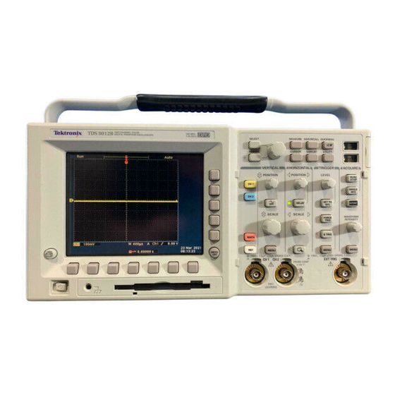
Figure 1: Oscilloscope with a 10X probe connected to the Probe Comp Terminals
Introduction
The oscilloscope, which displays voltage versus time, is an indispensable tool for testing and
troubleshooting circuits and taking electrical measurements. This tutorial will explain how to set
up the oscilloscope and take basic measurements.
Getting Started
Do the following steps to set up the oscilloscope.
1. Turn on the oscilloscope by pressing the power button located in the lower left-hand
corner. Wait for scope to boot-up. When a message shows up on the screen, press the
MENU OFF button.
2. When the oscilloscope powers up, it uses the settings that were in place when it was last
powered down. To return the oscilloscope to the factory settings, press the Save/Recall
button. Then press the button under the screen labeled Recall Factory Setup. Next press
the button on the right of the screen labeled OK Confirm Factory Init.
University of Portland
Oscilloscope Tutorial
Tektronix TDS3012B and TDS3012
- p. 1 of 9 -
Oscilloscope - TDS3012B.docx
Advertisement

Subscribe to Our Youtube Channel
Related Manuals for Tektronix TDS3012B


Summary of Contents for Tektronix TDS3012B
- Page 1 Oscilloscope Tutorial Tektronix TDS3012B and TDS3012 Figure 1: Oscilloscope with a 10X probe connected to the Probe Comp Terminals Introduction The oscilloscope, which displays voltage versus time, is an indispensable tool for testing and troubleshooting circuits and taking electrical measurements. This tutorial will explain how to set up the oscilloscope and take basic measurements.
- Page 2 If the ground lead is connected anywhere else in a circuit, it will short that node to earth ground. University of Portland - p. 2 of 9 - Oscilloscope - TDS3012B.docx...
- Page 3 In Figure 3, for example, there are 2.5 divisions in one period of the wave, so the period is 2.5 divisions * 400 µS = 1 mS. University of Portland - p. 3 of 9 - Oscilloscope - TDS3012B.docx...
- Page 4 When the vertical position knob (Figure 6) is rotated, the signal slides up or down and the arrow that marks the location of ground (0 Volts) is updated. The horizontal position knob (Figure 7) slides the signal left or right. University of Portland - p. 4 of 9 - Oscilloscope - TDS3012B.docx...
- Page 5 (0 Volts). This mode is used to check where ground is on the screen. (There is also an arrow on the left side of the screen that marks the ground level.) University of Portland - p. 5 of 9 - Oscilloscope - TDS3012B.docx...
- Page 6 The trigger level knob controls the trigger level (see Figure 11). In order for the oscilloscope to trigger properly, the trigger level must be set to a voltage that the input signal crosses. Figure 11: Trigger Level Knob University of Portland - p. 6 of 9 - Oscilloscope - TDS3012B.docx...
- Page 7 Δ symbol in the top right of the screen (see Figure 13). The time measurement will be most accurate if the horizontal scale is adjusted so that the time difference is as wide as possible. Figure 14: Cursor Knob and Select Button University of Portland - p. 7 of 9 - Oscilloscope - TDS3012B.docx...
- Page 8 Select button and then turn the knob. The voltage difference between the cursors is displayed after the Δ symbol. Figure 17: Cursor Knob and Select Button University of Portland - p. 8 of 9 - Oscilloscope - TDS3012B.docx...
- Page 9 Probe Setup button. The value should be 10X if a 10X probe is connected to the input (and 1X if a coax cable is connected). University of Portland - p. 9 of 9 - Oscilloscope - TDS3012B.docx...
Need help?
Do you have a question about the TDS3012B and is the answer not in the manual?
Questions and answers