Table of Contents
Advertisement
Quick Links
Advertisement
Table of Contents

Related Manuals for CYP CLUX-1HLR


Summary of Contents for CYP CLUX-1HLR
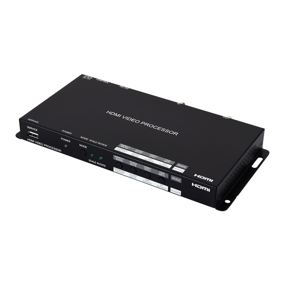
- Page 1 CLUX-1HLR HDMI Video Wall Rotation Processor Operation Manual Operation Manual...
- Page 3 DISCLAIMERS The information in this manual has been carefully checked and is believed to be accurate. Cypress Technology assumes no responsibility for any infringements of patents or other rights of third parties which may result from its use. Cypress Technology assumes no responsibility for any inaccuracies that may be contained in this document.
- Page 4 SAFETY PRECAUTIONS Please read all instructions before attempting to unpack, install or operate this equipment and before connecting the power supply. Please keep the following in mind as you unpack and install this equipment: • Always follow basic safety precautions to reduce the risk of fire, electrical shock and injury to persons.
-
Page 5: Table Of Contents
CONTENTS 1. Introduction ............1 2. Applications .............1 3. Package Contents ..........2 4. System Requirements ........2 5. Features ............2 6. Operation Controls and Functions ....3 6.1 Front Panel ..........3 6.2 Rear Panel ..........4 6.3 Video Wall Control Software ....5 6.3.1 Software Operation ...... -
Page 6: Introduction
1. INTRODUCTION This HDMI Video Wall Rotation Processor is capable of scaling and rotating the input source to nearly any angle and size desired. Its the ideal solution for presenting sources across the unique video display arrangements often found in commercial displays, control rooms, or classrooms. -
Page 7: Package Contents
3. PACKAGE CONTENTS • 1×HDMI Video Wall Rotation Processor • 1×5V/2.6A DC Power Adapter • 1×Shockproof Feet (Set of 4) • 1×Operation Manual 4. SYSTEM REQUIREMENTS • HDMI source equipment such as media players, video game consoles or set-top boxes. •... -
Page 8: Operation Controls And Functions
6. OPERATION CONTROLS AND FUNCTIONS 6.1 Front Panel ASPECT AUDIO VIDEO SERVICE POWER MODE SCALE RATIO MUTE STILL INFO. WARPING AUDIO 360º 45º SCALE ROTATE HDMI VIDEO PROCESSOR ROTATE ON/OFF MUTE ROTATE ROTATE 3 4 5 SERVICE PORT: This port is used for logo upload, EDID upload and firmware updates. -
Page 9: Rear Panel
Rotation Mode: Press to rotate the output video in 45 degree increments. Press and hold this button to display the OSD Info screen. Note: Activating 45° rotation will disable Warping Mode. 6.2 Rear Panel DC 5V RS-232 CONTROL OUT PORT: Connect to an HDMI TV, monitor or amplifier for digital video and audio output. -
Page 10: Video Wall Control Software
6.3 Video Wall Control Software The Video Wall Control software provides complete control over the Video Wall Rotation Processor via Ethernet or RS-232. This software can scan the local network, as well as any RS-232 connections on the PC, for controllable units to add to the current video wall grouping. Multiple video wall configurations can be stored in the software for quick local recall, or the configurations can be exported as a file for use in other video wall deployments. -
Page 11: Video Wall Unit Search
6.3.2 Video Wall Unit Search By clicking on the “Search” button at the top-right corner of the window, all Video Wall Rotation Processors that are located on the local network or are directly connected via RS-232 can automatically discovered. Each detected unit can then be added to the current video wall layout and assigned a unique ID number. - Page 12 unit and click “Arrange”. To remove an individual unit from the list, click the “X” next to it’s name. To remove all units, click the “Clear” button. After all desired displays have been added to the layout, each display must be connected to so that they may be controlled. If some displays that need to be a part of the layout are not currently available for connection, dummy monitors may be added in their place.
-
Page 13: Basic Unit Settings & Configuration
6.3.3 Basic Unit Settings & Configuration The basic configuration and settings for each connected unit can be set by selecting the unit to configure from the “Unit” section and then clicking on the “Setting” button in the upper-left “Common” section of the window. - Page 14 Configuration if your local network supports it. Click on “Apply” to confirm and activate any changes made to these settings. To return these settings to their factory defaults, click on the “Default” button. Note: If the IP address is changed then the IP address required for Software or Telnet access will also change accordingly.
- Page 15 6) OSD Info Timeout and Offset: The OSD Info timeout value (in seconds) and horizontal and vertical position may be set here. 7) Image Overlay Display: Enables or disables the custom image overlay feature. Note: Enabling OSD Info will automatically disable the Image Overlay.
- Page 16 6.3.3.2 Scaler Mode Configuration The “I/O” tab in Scaler Mode provides control over input and output functions such as EDID selection, audio/video mute, OSD Information, customized text overlay, and customized graphics overlay. To return these settings to their factory defaults, click on the “Default” button. 1) EDID Mode: Select the preferred EDID for the unit to use from the dropdown menu (FHD 2CH, FHD MCH, User, and Sink).
- Page 17 7) Text Overlay Content: Type the text to display when the Custom Text Overlay is active. The text string can be up to 32 characters long. 8) Custom Text Overlay Positioning: Set the horizontal and vertical position of the custom text overlay. 9) Image Overlay Display: Enables or disables the custom image overlay feature.
- Page 18 of the original aspect ratio. The “4:3”, “16:9”, and “16:10” options force the source to output at the specified aspect ratio relative to the currently selected output resolution. 3) Horizontal Flip: When enabled, flips the scaled output horizontally. 4) Video Freeze: When enabled, freezes the scaled video output. Note: While the output is frozen, audio will continue to play normally.
-
Page 19: Pre-Defined Video Wall Layouts
6.3.4 Pre-Defined Video Wall Layouts The position, size and angle of the display connected to each unit is set in the Layout window when in Rotation Mode. If you are currently in the Setting window, clicking on the “Layout” button in the upper- left “Common”... - Page 20 current layout. ■ Available Pre-Defined Layouts Tile Slash Vert Horiz Sharp After confirming the preferred layout, select all of the units involved in the video wall from the “Unit” section at the top of the window and then click on the “Set” button in the bottom-right corner of the window to upload the new layout configuration to all selected units.
-
Page 21: Customized Video Wall Layouts
6.3.5 Customized Video Wall Layouts The position, size and angle of the display connected to each unit is set in the Layout window when in Rotation Mode. If you are currently in the Setting window, clicking on the “Layout” button in the upper- left “Common”... - Page 22 The Unit information area on the left shows all of the relevant details of the currently selected display. You may freely reposition or resize any of the displays by simply clicking on them and dragging them around the layout space, or by typing numbers directly into the Unit information area.
- Page 23 1) Unit Information and Details: This section displays all of the relevant position, dimension, and orientation details of the selected unit/ display. Note: Only one unit’s details will be displayed if multiple units are currently selected. ■ ID: The ID number of the currently selected unit/display. ■...
- Page 24 the viewable portion of the display. After changing this value, press the enter key to commit the change to the layout. Note: Bezel measurements are optional. Bezel values subtract from the entered horizontal and vertical measurements of the display and reduce the size of the viewable portion of the display in the layout window.
-
Page 25: Multi-Zone Video Wall Layouts
6.3.6 Multi-Zone Video Wall Layouts Though this unit’s input is limited to a maximum resolution of 1080p, it is possible to generate large, flexible, video walls from 4K, or larger, sources by using a traditional 4K+ capable video wall splitter product with each output of the video wall splitter generating a 1080p block of video which is then further distributed to each group of Video Wall Rotation Processors. - Page 26 4) Zone Grid Row: Sets the number of zones, vertically, within the full layout. 5) Background Load: Click this button to load a graphic image to use as a background for the video wall(s) to help visualize the effect of the whole layout on the source video.
-
Page 27: Configuration Export/Import
6.3.7 Configuration Export/Import The Configuration and File sections of the main window provide ways to save/load populated layout configurations as well as to export/ import configurations/layouts to a file on your local PC. A saved layout configuration includes unit connection information as well as display orientation. - Page 28 2) File: This section provides a way to export saved layouts and configurations to a file on the local PC, or to import previously saved layouts and configurations. Note: Exported configurations and layouts are stored as protected *.zip files and cannot be opened for direct editing. ■...
-
Page 29: Rs-232 Control
6.4 RS-232 Control Unit Controlling PC Serial Port Settings Definition Definition Baud Rate 19200 Data Bits Parity Bit None Stop Bits Flow Control None 6.5 Telnet Control Before attempting to use Telnet control, please ensure that both the unit and the PC are connected to the same active networks. To Access the Command Line Interface (CLI) Click Start, type “cmd”... -
Page 30: Rs-232 And Telnet Commands
6.6 RS-232 and Telnet Commands COMMAND Description and Parameters get fw ver Show the unit's current firmware version. set factory default Reset the unit to the factory defaults. set in a edid N1 Set the EDID to be used by the HDMI input. Available values for N1: [FHD/2CH] [FHD/MCH]... - Page 31 COMMAND Description and Parameters get out a sync status Show the current sync state of the HDMI output. set out a osd info N1 Enable or disable the info OSD for the HDMI output. Available values for N1: [Enable OSD] [Disable OSD] get out a osd info...
- Page 32 COMMAND Description and Parameters set ip mode N1 Set the IP address assignment mode. Available values for N1: [Static IP mode] [DHCP mode] get ip mode Show the current IP address assignment mode. get ipconfig Show the unit's current IP configuration information. set ip addr N1...
- Page 33 COMMAND Description and Parameters get telnet port Show the unit’s current access Telnet port. usb update mcu Begins the firmware update process and searches for a firmware file on a thumb drive in the USB port. Note: The firmware’s filename must be “FIRMWARE.BIN”. usb update edid...
- Page 34 COMMAND Description and Parameters set rot360 a mode N1 Control the unit’s 360° automated rotation demonstration mode. Available values for N1: [Stop rotation] [Rotate counterclockwise slowly] [Rotate clockwise slowly] [Rotate counterclockwise quickly] [Rotate clockwise quickly] Note: Rotation Mode only. Automatically disables Warping. get rot360 a mode...
- Page 35 COMMAND Description and Parameters Available values for N1: [Native] [480p@60Hz] [720p@60Hz] [1080p@60Hz] [576p@50Hz] [720p@50Hz] [1080p@50Hz] [1080p@24Hz] [1080p@25Hz] [1080p@30Hz] [1024×768@60Hz] [1280×800@60Hz] [1280×1024@60Hz] [1366×768@60Hz] [1440×900@60Hz] [1600×900@60Hz (RB)] [1600×1200@60Hz] [1680×1050@60Hz] [1920×1200@60Hz] Note: Scaler Mode only. get out a timing Show the universal timing number of the current resolution used by the HDMI output.
- Page 36 COMMAND Description and Parameters Note: Scaler Mode only. get in a contrast Show the current contrast level of the video source. set in a brightness N1 Set the brightness level of the video source. N1 = 0 ~ 100 [Brightness level] Note: Scaler Mode only.
- Page 37 COMMAND Description and Parameters Note: Scaler Mode only. get out a aspect ratio Show the current aspect ratio setting for the video shown on the HDMI output. set in a temperature N1 Set the color temperature of the video source. Available values for N1: [6500K] [9300K]...
- Page 38 COMMAND Description and Parameters set out a osd text N1 Set a text overlay string for display over the video output. N1 = {String} [32 characters max] get out a osd text Show the current text overlay string content. set out a text overlay N1 Enable or disable display of the custom text overlay string.
- Page 39 COMMAND Description and Parameters set out a osd bitmap N1 Enable or disable display of the User Bitmap image. Available values for N1: [Enable bitmap display] [Disable bitmap display] Note: Scaler Mode only. get out a osd bitmap Show the current state of the User Bitmap image display. set out a bitmap hpos N1...
-
Page 40: Connection Diagram
7. CONNECTION DIAGRAM 7.1 Basic Screen Array System Media Player HDMI Input 1×4 HDMI Splitter OUT 1 OUT 2 OUT 3 OUT 4 POWER EDID SYS-RST SYNC HDCP SERVICE POWER MODE ASPECT AUDIO VIDEO SCALE RATIO MUTE STILL INFO. SCALE ROTATE WARPING AUDIO 360º... -
Page 41: Advanced Screen Array System
7.2 Advanced Screen Array System Media Game Media Game Player Console Player Console Set-top Satellite Set-top Satellite Receiver Receiver HDMI Inputs 8×8 HDMI Matrix OUT A OUT B OUT C OUT D OUT E OUT F OUT G OUT H CANCEL MENU LOCK... -
Page 42: Quad-Zone Screen Array System
7.3 4K Quad-Zone Screen Array System 4K Media Player HDMI Input 1×4 4K HDMI Video POWER Wall Controller 1X4 UHD TV WALL CDPS-4KQ HDMI Outputs OUT 1 OUT 2 OUT 3 OUT 4 OUT 1 OUT 2 OUT 3 OUT 4 POWER EDID SYS-RST... -
Page 43: Specifications
8. SPECIFICATIONS 8.1 Technical Specifications HDMI Bandwidth 340MHz/10.2Gbps Input Port 1×HDMI Output Port 1×HDMI Control Ports 1×RS-232 (DE-9) 1×IP Control (RJ45) Baud Rate 19200bps Power Supply 5V/2.6 DC (US/EU standards, CE/FCC/UL certified) ESD Protection Human Body Model: ±8kV (Air Discharge) ±4kV (Contact Discharge) Dimensions 231.5mm×25mm×108mm (W×H×D) -
Page 44: Video Specifications
8.2 Video Specifications Scaler Mode Supported Resolutions (Hz) Input Output 640×480@60/72/75/85 800×600@56/60/72/75/85 1024×768@60/70/75/85 1280×768@60/75 1280×800@60 1280×960@60 1280×1024@60/75 1360×768@60 1366×768@60 1400×1050@60 1440×900@60 1600×900@60 (RB) ... -
Page 45: Audio Specifications
8.3 Audio Specifications HDMI Input/Output LPCM Max Channels 8 Channels Sampling Rate (kHz) 32, 44.1, 48, 88.2, 96, 176.4, 192 Bitstream Supported Formats Standard & High-Definition 8.4 Cable Specifications 1080p HDMI Cable Length 8-bit 12-bit Input Output... -
Page 46: Acronyms
9. ACRONYMS ACRONYM COMPLETE TERM Consumer Electronics Control Command-Line Interface DHCP Dynamic Host Configuration Protocol Digital Visual Interface EDID Extended Display Identification Data Graphical User Interface High-Definition HDCP High-bandwidth Digital Content Protection HDMI High-Definition Multimedia Interface HDTV High-Definition Television Internet Protocol Local Area Network LPCM Linear Pulse-Code Modulation... - Page 48 CYPRESS TECHNOLOGY CO., LTD. www.cypress.com.tw...
Need help?
Do you have a question about the CLUX-1HLR and is the answer not in the manual?
Questions and answers