
Related Manuals for Lippert 702-0008-10


Summary of Contents for Lippert 702-0008-10
- Page 1 Cool LiteRunner-LX800 PC/104 CPU Board Technical Manual TME-104-CLR-LX800-R1V3.doc Revision 1.3 / March 09 © LiPPERT Embedded Computers GmbH Hans-Thoma-Str. 11 D-68163 Mannheim http://www.lippertembedded.com/...
- Page 2 Technical Manual Cool LiteRunner-LX800 LiPPERT Document: TME-104-CLR-LX800-R1V3.doc Revision 1.3 Copyright © 2009 LiPPERT Embedded Computers GmbH, All rights reserved Contents and specifications within this manual are subject of change without notice. Trademarks MS-DOS, Windows, Windows 95, Windows 98, Windows NT and Windows XP are trademarks of Microsoft Corporation.
-
Page 3: Table Of Contents
Table of Contents Overview Introduction ..................1 Features....................1 Block Diagram..................2 Ordering Information................3 Cool LiteRunner-LX800 Models ..............3 Cable Sets and Accessories ................ 3 Specifications ..................4 Electrical Specifications ................4 Environmental Specifications ..............4 MTBF ...................... 4 Mechanical..................... - Page 4 Backlight Connector ................17 Display Voltage Jumpers................18 Compact Flash Socket ................18 Ethernet Controller ................19 Ethernet Interface .................. 19 On Board Power Supply ............... 20 Power Connector ..................20 EIDE Port ..................... 21 EIDE Connector ..................21 PS/2 Interface..................22 Keyboard and Mouse Connector ..............
- Page 5 Configuring the XpressROM BIOS .............. 35 Trouble Shooting BIOS Settings ..............43 Programming GPIO Signals ..............44 Programming Serial Port COM3 ............45 LIVE LED Programming................ 46 Watchdog Programming ..............47 Reading Temperatures................. 48 Drivers....................49 Address Maps Memory Address Map................50 I/O Address Map .................
- Page 6 Acronyms AC97 Audio Codec 97 ACPI Advanced Configuration and Power Management Interface Advanced Encryption Standard Advanced Power Management Advanced Technology Attachment BIOS Basic Input Output System Bits Per Pixel Compact Disc Compact Flash Communication Equipment Central Processing Unit Cathode Ray Tube Cool LiteRunner Digital-to-Analog-Converter Double Date Rate...
-
Page 7: Overview Introduction
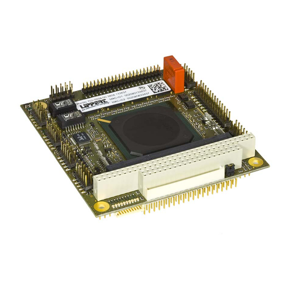
1 Overview 1.1 Introduction The Cool LiteRunner-LX800 (CLR-LX800) is a PC/104 board with AMD’s Geode™ LX processor and has a very good performance- power- ratio. The board comprises all peripherals needed for an embedded PC on a small 3.775" by 4.050" printed circuit board. On the top side it is fully plug-in compatible with the Cool LiteRunner 2. -
Page 8: Block Diagram
Block Diagram LPT/ Parallel COM1 IDC 26 RS232/485 Line Driver 2.54 mm IDC 10 LTC1334 2.54 mm SST FWH SST25LF080A COM2 Super I/O RS232/485 Line Driver ITE8712 IDC 10 LTC1334 2.54 mm PS/2-MS/KB MISC PS/2 SUPERVISORY IDC 10 I²C 2.54 mm GP I/O COM3/ IrDA UPD78F0511GA... -
Page 9: Ordering Information
1.2 Ordering Information Cool LiteRunner-LX800 Models Order number Description 702-0008-10 CLR-LX800 with LCD+VGA-CRT, AMD GEODE LX800@0.9W (500 MHz), low power consumption, 256MB DDR SDRAM, 4x USB2.0, IrDA, RTC, Battery, EIDE, Compact Flash socket, 3x COM, LPT (EPP/EPC), PS/2 Keyboard, PS/2 Mouse,... -
Page 10: Specifications
1.3 Specifications Electrical Specifications Supply voltage +5 V DC Rise time < 10 ms Supply voltage tolerance ± 5%** Inrush current 8 A, 25 µS Supply current maximal 1,2 A (Memtest86 v1.70) ** typical 0,84 A (Windows XP idle mode) typical 0,045 A (suspend to ram mode) Environmental Specifications Operating:... -
Page 11: Mechanical
1.4 Mechanical Dimensions (LxW) 95.9 mm x 90.2 mm (including I/O extension) Height max. 14 mm on topside above PCB max. 12 mm on bottom side above PCB Weight 102 gramme Mounting 4 mounting holes Note: It is strongly recommend using plastic spacers instead of metal spacers to mount the board. -
Page 12: Bottom (Vertical Mirrored)
BOTTOM (vertical mirrored) Pin1 Pin2 TME-104-CLR-LX800-R1V3.doc Rev. 1.3 6(53) -
Page 13: Getting Started Connector Locations
2 Getting Started 2.1 Connector Locations COM2 COM1 EIDE Mini-PCI PC/104 ETH2 ETH1/USB1 Audio/USB2 PS/2 The connectors' pin 1 is marked TME-104-CLR-LX800-R1V3.doc Rev. 1.3 7(53) -
Page 14: Bottom
Bottom USB3/4 SUPERVISORY Compact Flash Socket PC/104 Recovery Board Flat Panel LVDS Backlight The connectors' pin 1 is marked TME-104-CLR-LX800-R1V3.doc Rev. 1.3 8(53) -
Page 15: Jumper Locations
2.2 Jumper Locations Jumper Termination Serial Interface Jumper Battery Jumper LVDS and Backlight Power Supply TME-104-CLR-LX800-R1V3.doc Rev. 1.3 9(53) -
Page 16: Led Indicators
2.3 LED indicators The onboard LED indicators provide a very comfortable way to check the board’s status. The boot success, power status, IDE accesses, Watchdog and Ethernet accesses are all visible. The LED indicators are located on top of the board, near the PC/104 connector. SPD2 Yellow LED lights up if 100Mbit connection of Ethernet 2 is established. -
Page 17: Hardware Setup
Use the cable set provided by LiPPERT to connect the Cool LiteRunner-LX800 to a VGA monitor. Connect either PS/2 or USB keyboard and mouse, respectively. Use the 44-wire cable to connect the harddisk. -
Page 18: Module Description Processor
3 Module Description 3.1 Processor The AMD Geode LX 800@0.9W processor delivers one of the best performance per watt in the industry, providing x86 power and versatility to embedded products. Its architecture and high level of integration guarantees longer battery life and allows very small designs, while delivering full x86 functionality. -
Page 19: Companion
• GeodeLink PCI Bridge • Security Block For further information, please refer to the data book of the AMD Geode LX 800 3.2 Companion AMD Geode™ CS5536 companion device The AMD Geode™ CS5536 companion device is designed to work with an integrated processor North Bridge component such as the AMD Geode™... -
Page 20: Graphics-Controller
3.3 Graphics-Controller The graphics controller is integrated in the Geode LX processor and does high performance 2D- graphics handling. CRT monitors can be used as well as TFT- and LVDS displays. Therefore, two different connectors are on the board. It is possible to switch between CRT and TFT via BIOS or driver settings. -
Page 21: Vga Connector
Refresh Rate Min. GLIU Frequency Resolution Color Depth (bpp) Dot Clock (MHz) (Hz) (MHz) 1280 x 1024 8, 16, or 24/32 108.000 8, 16, or 24/32 129.600 8, 16, or 24/32 133.500 8, 16, or 24/32 135.000 8, 16, or 24/32 157.500 8, 16, or 24/32 172.800... -
Page 22: Flat Panel And Lvds Configuration
Flat Panel and LVDS Configuration Flat panel and LVDS have the same display options as shown in the table: Setting Possible Values Flat Panel Type Auto, TFT, LVDS Resolution 320x240, 640x480, 800x600, 1024x768, 1152x864, 1280x1024, 1600x1200 Data Bus Type 18/24 Bits, 2ppc Refresh Rate 60 70, 72, 75, 85, 90, 100 Hz HSYNC Polarity... -
Page 23: Lvds Connector
LVDS Connector Connector type Hirose DF13 20-pin header, single row Signal Signal SW-VDD SW-VDD TX3+ TX3- TXCLK- TXCLK+ TX2+ TX2- TX1- TX1+ TX0+ TX0- DDC DATA DDC CLK Backlight Connector Connector type Hirose DF13 8 pin, single row Signal +12 Volts +12 Volts +5 Volts +5 Volts... -
Page 24: Display Voltage Jumpers
Display Voltage Jumpers Jumper LVDS and Backlight Connector type IDC6 jumper 2.00 mm. Use a 2 mm jumper between 1-3 or 3-5 to select the backlight voltage. Use a 2 mm jumper between 2-4 or 4-6 to select the display voltage. Signal Signal +12 volts... -
Page 25: Ethernet Controller
3.5 Ethernet Controller On the board there are two Intel 82551IT Fast Ethernet Controllers mounted. The 82551IT is an evolutionary addition to Intel’s family of 8255x controllers. It provides excellent performance by offloading TCP, UDP and IP checksums and supports TCP segmentation off-load for operations such as Large Send. -
Page 26: On Board Power Supply
3.6 On Board Power Supply The on board power supply generates all necessary voltages from the single supply voltage of 5 volts. The generated 3.3 volts are available on the connectors "Flat Panel" and "LVDS". Note This 3.3 V must not be used to supply external electronic devices with high power consumption like other PC/104 boards or displays. -
Page 27: Eide Port
3.7 EIDE Port An EIDE (Enhanced Integrated Drive Electronics) port is provided by the chipset to connect one drive. The connected device must be set as slave. To enhance the performance, this port has a 100 MB/s IDE controller in UDMA mode per the ATA-5 specification The EIDE port is available on a standard 44-pin header (2 mm) for 2.5"... -
Page 28: Ps/2 Interface
3.8 PS/2 Interface PS/2-connectors for mouse and keyboard are shared with several system signals. An adapter cable for the PS/2 devices is available. Keyboard and Mouse Connector Connector type IDC10 pin header 2.54 mm Signal Signal Speaker Mouse Clock Reset-In Mouse Data KB Data KB Clock... -
Page 29: Usb 2.0 Connector 1
USB 2.0 Connector 1 Connector type IDC10 pin header 2.54 mm Signal Signal ETH1-TX+ ETH1-TX- ETH1-RX+ ETH1-RX- USB1+ USB1- VCC_USB1 USB-GND USB 2.0 Connector 2 Connector type IDC10 pin header 2.54 mm Signal Signal USB2+ USB2- VCC_USB2 USB-GND LINEIN-L LINEIN-R LINEOUT-L LINEOUT-R MICROPHON... -
Page 30: Serial Ports
3.10 Serial Ports The serial ports are located on two IDC10 headers "COM1" and "COM2". Adapter cables with standard DSUB-9 male connectors are available. The ports either work in RS232 or RS485 mode, selectable in BIOS. When entering Motherboard Device Configuration Serial and Parallel Device Configurations, COM Port 1 Mode and COM Port 2 Mode can be selected. -
Page 31: Com1/2
COM1/2 Connector type IDC10 pin header 2.54 mm RS232 RS485 RS232 RS485 Not used RXD+ RXD- TXD+ TXD- Not used Not used Not used Not used +5 Volts +5 Volts RS485-Termination Jumpers Connector type IDC12 pin header 2.00 mm Use 2 mm jumpers to terminate lines correctly. There are two jumpers COM1 and COM2, respectively. -
Page 32: Irda Interface
3.11 IrDA Interface The IrDA interface signals IRRX and IRTX are located on the supervisory connector, see chapter 3.18. The IrDA interface shares its UART with COM3, the normal serial port 3 cannot be used at the same time as the IrDA interface. To use the IrDA interface an external transmitter must be connected to the IrDA signals and the in BIOS IrDA mode has to selected. -
Page 33: Parallel Port Lpt1
3.12 Parallel Port LPT1 The parallel port is located on an IDC26 header. An adapter cable with a standard DSUB-25 female connector is available. The parallel port is programmable in BIOS. Entering Motherboard Device Configuration Serial and Parallel Device Configurations, configuration of LPT1 is accessible. -
Page 34: Lemt Functions
3.13 LEMT functions The onboard Microcontroller implements power sequencing and LEMT (LiPPERT Enhanced Management Technology) functionality. The microcontroller communicates via the System Management Bus with the CPU/Chipset. The following functions are implemented: • Total operating hours counter Counts the number of hours the module has been run in minutes. -
Page 35: External Power-Button
3.16 External Power-Button The Power-Button signal is located on the IDC10 Header PS/2. To power up/down the board the signal Power-Button must be pulled to GND. Connector type IDC10 pin header 2.54 mm Signal Signal Speaker Mouse Clock Reset-In Mouse Data KB Data KB Clock +5 Volt Standby... -
Page 36: Supervisory
3.18 Supervisory The Cool LiteRunner-LX800 provides a 25-pin Supervisory Connector on its bottom side. The table below shows the assignment of the different signals. Connector type DF14 25 pin header 1.25 mm, single row Signal Signal 5V / 10mA 3,3V / 15mA GPIO30 GPIO31 GPIO32... -
Page 37: Mini-Pci Bus Interface
3.19 Mini-PCI BUS Interface The Mini-PCI specification defines a small form factor daughter card for the 32bit PCI bus that can be used on CPU-boards in which standard PCI cards cannot be used due to mechanical constraints. A CPU board with such a card can easily be enhanced with new functionality. The onboard Type IIIA Mini-PCI Slot can be used to extend the system easily with peripheral functionality, like WLAN modules, Fire Wire-, Serial- and USB 2.0- ports. - Page 38 Signal Signal n.c. n.c. n.c. n.c. PCI_INTA# 3.3V PCI_INTB# n.c. 3.3V SBY CLK_33_MPCI_R PCI_RST# 3.3V REQ1_MPCI# GNT1_MPCI# 3.3V PCI_AD31 PME# PCI_AD29 n.c. PCI_AD30 PCI_AD27 3.3V PCI_AD25 PCI_AD28 n.c. PCI_AD26 PCI_C/BE3# PCI_AD24 PCI_AD23 PCI_AD23 PCI_AD21 PCI_AD22 PCI_AD19 PCI_AD20 PCI_PAR PCI_AD17 PCI_AD18 PCI_C/BE2# PCI_AD16 PCI_IRDY#...
- Page 39 Signal Signal PCI_AD14 PCI_AD15 PCI_AD13 PCI_AD12 PCI_AD11 PCI_AD10 PCI_AD09 PCI_AD08 PCI_C/BE0# PCI_AD07 3.3V 3.3V PCI_AD06 PCI_AD05 PCI_AD04 PCI_AD02 PCI_AD03 PCI_AD00 n.c. PCI_AD01 n.c. n.c. n.c. n.c. n.c. n.c. n.c. n.c. n.c. n.c. n.c. n.c. n.c. n.c. n.c. Note: All VI/O pins are connected to +3.3V. The maximum current is limited to 1.0 amp for each voltage.
-
Page 40: Pc/104 Bus Interface
3.20 PC/104 Bus Interface The PC/104 bus is a modification of the industry standard (ISA) PC bus specified in IEEE P996. The PC/104 bus has different mechanics than P966 to allow the stacking of modules. The main features are: • Supports programmable extra wait state for ISA cycles •... -
Page 41: Using The Module
4 Using the Module 4.1 BIOS The Cool LiteRunner-LX800 is delivered with a Insyde Technology XpressROM BIOS. The default setting guarantees a "ready to run" system, even without a BIOS setup backup battery. The BIOS is located in flash memory and can be easily updated on board with software under DOS. All setup changes of the BIOS are stored in the CMOS RAM. - Page 42 Field Selection To move between fields in Setup, use the keys listed below: Function Move between fields +, - Selects next/previous values in fields Enter Go to the submenu for the field To previous field then to exit menu In order to save your settings, select Save values and Exit and confirm with Y. Should you want to discard everything, select Exit Without Save.
- Page 43 The Drive Configuration menu allows to configure connected EIDE devices. An IDE device can be disabled that its power stays off after restart. With the help of 80-Conductor Cable Sense the access system memory mode of an device is set. For running a device in UDMA-4 mode a 80 pin cable is required.
- Page 44 The Serial and Parallel Device Configurations menu allows to configure COM1, COM2, COM3 and LPT1. COM-Ports 1 and 2 can be switched between RS232 and RS485. It is possible to chance the resource and interrupts of all ports. Hard Drive Setting Options Serial Port 1/2 Disabled, 0x3f8 IRQ 4, 0x2f8 IRQ 3,...
- Page 45 The DDMA Configuration menu allows to activate the DMA Mode for Channel 0 to 7. The Graphics Configuration menu allows to set up different displays and their several functions. Possible options are mentioned in chapter 3.4. TME-104-CLR-LX800-R1V3.doc Rev. 1.3 39(53)
- Page 46 The PCI Configuration menu contents options about PCI interrupts and USB. There the PCI-ports can be referred to an interrupt. In the USB Settings the different controllers can be selected. The port 4 can be changed to client mode. The audio controller can be disabled if not needed. System Clock/PLL Configuration lets you define the CPU and PLL settings.
- Page 47 The Power Management menu gives control over power down modes supported. Miscellaneous Configuration controls various other features TME-104-CLR-LX800-R1V3.doc Rev. 1.3 41(53)
- Page 48 ISA I/O and Memory Configuration allows setting the boards ISA memory and I/O map. The menu Boot Order specifies the order in which the BIOS tries the various mass memory devices for a bootable operating system. Boot over LAN is also supported. TME-104-CLR-LX800-R1V3.doc Rev.
-
Page 49: Trouble Shooting Bios Settings
Trouble Shooting BIOS Settings It may happen that the BIOS is configured that the Cool LiteRunner-LX800 does not start at all. To repair this, the default values of the BIOS can be automatically loaded at boot time. To load these, the power must be switched on and off again within 2 seconds. -
Page 50: Programming Gpio Signals
4.2 Programming GPIO Signals The Cool LiteRunner-LX800 general purpose I/O signals (GPIO) are part of the ITE8712 SuperI/O. They are located in Logical Device 7 of the Super I/O and can be programmed using in/out statements on Index/Data registers 2Eh/2Fh. GPIO's 1x belong to GPIO set #1, GPIO's 2x to set #2 and so on, up to set #5. -
Page 51: Programming Serial Port Com3
4.3 Programming Serial Port COM3 The transmitter of the RS485 interface must be disabled in receive mode, and enabled in transmit mode. The receiver has to be enabled in BIOS, by selecting the RS485 mode. Therefore, setting GPIO2x of the ITE Super I/O Bit 0 to ‘0’... -
Page 52: Live Led Programming
4.4 LIVE LED Programming The LIVE LED can be programmed by users. The cathode of the mounted LED is connected to a GPIO pin of the Super I/O. If the input has ground potential the LED is on. That pin is set as simple I/O and can be easily reached over the port address. The following program chances the state of the LIVE LED. -
Page 53: Watchdog Programming
4.5 Watchdog Programming Since the Watchdog is disabled in delivery status, it must be set up for proper use. The Watchdog is an internal feature of the ITE8712 Super I/O. If the Watchdog is activated and the timer is not set back within a programmed amount of time, the board does a system reset. In order to read back the watchdog event read Bit 0 of Watchdog status register 71h in LDN7. -
Page 54: Reading Temperatures
4.6 Reading Temperatures There are temperature sensors available that allow measurement of the CPU's chip temperature as well as the boards ambient temperature. These are shown in the BIOS setup screens, see above. This example is meant to be compiled using gcc under Linux. #include <stdio.h>... -
Page 55: Drivers
4.7 Drivers Software drivers for sound, Ethernet, AES and graphics adapter are available for the CLR-LX800. These drivers can be downloaded from LiPPERT's website ttp://www.lippertembedded.com. 8 3 H Follow the installation instructions that come with the drivers. TME-104-CLR-LX800-R1V3.doc Rev. 1.3... -
Page 56: Address Maps
5 Address Maps This section describes the layout of the CPU memory and I/O address spaces. Note Depending on enabled or disabled functions in the BIOS, other or more resources may be used 5.1 Memory Address Map Address Range Address Range (Hex) Size Description 1024K... -
Page 57: I/O Address Map
5.2 I/O Address Map The system chip set implements a number of registers in I/O address space. These registers occupy the following map in the I/O space. Address Range Description 0000 - 000F DMA-Controller 0020 - 0021 Programmable Interrupt controller 002E - 002F System 0040 - 0043... -
Page 58: Interrupts
5.3 Interrupts System Resource Parity error Timer PS/2 Keyboard (Secondary interrupt controller 2) Serial port 2 Serial port 1 PCI INTC# (ETH0) Serial port 3 Parallel port 1 Real time clock ACPI controller PCI INTA# (Mini-PCI, AES, Grafik) PCI INTB# (Mini-PCI, Audio) PS/2 Mouse Numeric coprocessor Primary IDE channel... -
Page 59: Pc/104 Bus Address Space
5.5 PC/104 Bus Address Space The PC/104 bus address space mapping can be changed in the BIOS setup. The table shows the factory default values. Range Start Address End Address Size Description I/O 0 128 bytes IT8712 Positive Decode I/O Range 1 I/O 1 64 bytes IT8712 Positive Decode I/O Range 2... -
Page 60: Appendix A, Contact Information A
Appendix A, Contact Information Headquarters LiPPERT Embedded Computers GmbH Hans-Thoma-Straße 11 68163 Mannheim Germany Phone +49 621 4321410 +49 621 4321430 E-mail sales@lippertembedded.com support@lippertembedded.com Website www.lippertembedded.com US Office LiPPERT Embedded Computers, Inc. 5555 Glenridge Connector, Suite 200 Atlanta, GA 30342... -
Page 61: Appendix B, Additional Information B
Appendix B, Additional Information B.1 Additional Reading AMD Geode™ LX Processors Data Book AMD Geode™ CS5536 Companion Device Data Book Datasheet LPC interface ITE IT8712F, available at http://www.ite.com.tw B.2 PC/104 A copy of the latest PC/104 can be obtained from the PC/104 Consortium's website at http://www.pc104.org TME-104-CLR-LX800-R1V3.doc Rev. -
Page 62: Appendix C, Getting Help C
8 4 H Please allow one working day for an answer! Technical manuals as well as other literature for all LiPPERT products can be found in the Products section of LiPPERT's website www.lippertembedded.com. Simply locate the product in question and follow the link to its manual. -
Page 63: Appendix D, Revision History D
Appendix D, Revision History Filename Date Edited by Change TME-104-CLR_LX800-R0V0 2008-05-14 preliminary draft TME-104-CLR-LX800-R1V0 2008-12-23 Minor corrections TME-104-CLR-LX800-R1V1 2008-01-08 Ch. 1.4 dimensions added TME-104-CLR-LX800-R1V2 2009-02-13 Ch. 4.5 program failure corrected TME-104-CLR-LX800-R1V3 2009-03-11 Ch. 1.3, max. current corrected, footnote added TME-104-CLR-LX800-R1V3.doc Rev.
Need help?
Do you have a question about the 702-0008-10 and is the answer not in the manual?
Questions and answers