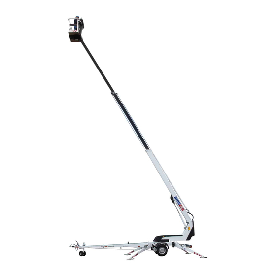
Dinolift 180T Operating Instructions Manual
Hide thumbs
Also See for 180T:
- Operating instructions manual (71 pages) ,
- Quick start manuals (2 pages)

Subscribe to Our Youtube Channel
Related Manuals for Dinolift 180T


Summary of Contents for Dinolift 180T
- Page 1 OPERATING INSTRUCTIONS Raikkolantie 145 FI-32210 LOIMAA Tel. +358 2 762 5900 Fax. +358 2 762 7160 dino@dinolift.com www.dinolift.com...
- Page 2 DINO 180T-1...
- Page 3 DINO 180T-1 OPERATING INSTRUCTIONS 4681… Valid from serial number...
- Page 4 DINO 180T-1...
-
Page 5: Table Of Contents
DINO 180T-1 CONTENTS REACH DIAGRAM..........................7 TECHNICAL SPECIFICATION ......................8 GENERAL SAFETY REGULATIONS....................9 REGULAR INSPECTION ........................11 WORKSITE INSPECTION........................12 OPERATION OF SAFETY DEVICES....................13 OPERATING CONTROLS ........................15 OPERATING CONTROLS ON CHASSIS PANEL................15 OPERATING CONTROLS OF DRIVE SYSTEM................16 OPERATING CONTROLS OF OUTRIGGERS ...................16 OPERATING CONTROLS ON THE PLATFORM ................17 MEASURES TO BE TAKEN IF THE LIFT IS AT RISK OF LOSING ITS STABILITY ....19... - Page 6 LIMIT-SWITCHES..........................84 OTHER MARKINGS ..........................85 ADJUSTMENT VALUES OF MOVEMENT SPEEDS ..............86 ELECTRIC COMPONENTS 180T-1 N:O 4681 → → → → ................88 WIRING DIAGRAM ..........................91 ELECTRIC DIAGRAM 180T N:O 4681 → → → → ..................92 HYDRAULIC COMPONENTS 180T-1 N:O 4681 → → → → ..............105...
-
Page 7: Reach Diagram
DINO 180T-1 REACH DIAGRAM... -
Page 8: Technical Specification
DINO 180T-1 TECHNICAL SPECIFICATION Max. working height 18.0 m Max. platform height 16.0 m Max. outreach 10.7 m Boom rotation continuous Platform rotation 90° Turn area refer to reach diagram Support width 3.88 m Transport width 1.78 m Transport length 7.35 m... -
Page 9: General Safety Regulations
DINO 180T-1 GENERAL SAFETY REGULATIONS Make yourself familiar with these operation instructions before using the lift! Keep these operating instructions in the place reserved for them. Make sure that all users of the lift are familiar with these instructions. Advice the new users and strictly follow all instructions given by the manufacturer. - Page 10 DINO 180T-1 Do not use ladders, steps or other similar equipment on the platform. Never throw any objects from the platform. The lift must not be used for transferring goods or persons between different floors or working levels. Never disable the operation of any safety device.
-
Page 11: Regular Inspection
DINO 180T-1 REGULAR INSPECTION A thorough inspection of the lift must be carried out at least once every twelve (12) months. The inspection shall be carried out by a technically trained person who is familiar with the operation and structure of the lift. -
Page 12: Worksite Inspection
DINO 180T-1 WORKSITE INSPECTION 1. General Is the lift suited for the intended job? Is the performance of the lift sufficient for the job? (reach, loadability etc.) Is the position of the lift safe? Is the lighting on the worksite sufficient? 2. -
Page 13: Operation Of Safety Devices
DINO 180T-1 OPERATION OF SAFETY DEVICES 1. Support outriggers The safety limit switch RK3 prevents the operation of the outriggers and the driving device when the boom does not rest on the transport support. The switch is located on the tow-bar at the transport support. - Page 14 DINO 180T-1 3. Lifting of the boom All the lift’s support outriggers must be in the support position before the boom is lifted. Make sure that the wheels are off the ground. The safety limit switches RK11, RK12, RK13 ja RK14 are located on the support outriggers.
-
Page 15: Operating Controls
DINO 180T-1 OPERATING CONTROLS OPERATING CONTROLS ON CHASSIS PANEL 1. Selector switch 0 - ignition off 1 - outrigger circuit, hydraulic drive 2 -controlling the boom from the platform panel 3 -controlling the boom from the chassis panel 2. Start button 3. -
Page 16: Operating Controls Of Drive System
DINO 180T-1 OPERATING CONTROLS OF DRIVE SYSTEM 28A. Forward - backward 28A + 28L drive to the left 28A + 28L drive to the right OPERATING CONTROLS OF OUTRIGGERS 12. Rear outrigger, right 13. Rear outrigger, left 14. Front outrigger, left 15. -
Page 17: Operating Controls On The Platform
DINO 180T-1 OPERATING CONTROLS ON THE PLATFORM Close the cover of the chassis control panel before operating the platform controls. The cover must not be locked while the lift is in operation. 17. Control lever TELESCOPE BOOM BOOM TO THE LEFT... - Page 18 DINO 180T-1 18. Signal lights green inside allowed outreach range at the border of allowed outreach range 20. Emergency descent device start button 21. Retraction of telescope 22. Emergency stop push to stop pull to reset 24. Socket outlet 230VAC/ (2 pcs.) 25.
-
Page 19: Measures To Be Taken If The Lift Is At Risk Of Losing Its Stability
DINO 180T-1 MEASURES TO BE TAKEN IF THE LIFT IS AT RISK OF LOSING ITS STABILITY The reason for the reduced stability can be a fault in the lift, the wind or other lateral force, collapse of the standing base or negligence in providing sufficient support. In most cases a sign of the reduced stability is the inclination of the lift. -
Page 20: Start-Up
DINO 180T-1 START-UP 1. Ground stability make sure that the ground is even and hard enough to support the lift in a steady level position Soil material Density Max. ground pressure kg/cm² Gravel High density Medium density Loose Sand High density... - Page 21 DINO 180T-1 3. Connection of power supply to the lift A. POWERED BY AC-SUPPLY connect the mains cable to the power supply turn on the main switch (Fig. A) for maximum out of the electric motor the voltage must 230 VAC (-...
- Page 22 DINO 180T-1 7. Lower the front support outriggers (on the tow-bar side) 8. Lower the rear support outriggers (do not damage the tow-bar jockey wheel) 9. Level the chassis with the outriggers with the help of the level gauge (16)
-
Page 23: Operating The Lift From The Chassis Panel
DINO 180T-1 OPERATING THE LIFT FROM THE CHASSIS PANEL Turn the selector switch (1) to position 3 now you are able to operate the boom with levers 7, 8, and 9 on the chassis panel test the operation of the emergency descent system as follows: 1. -
Page 24: Operating The Lift From The Platform Panel
DINO 180T-1 OPERATING THE LIFT FROM THE PLATFORM PANEL Turn the selector switch (1) to position 2 and take away the key Do not lock the chassis control panel cover with the key. now you can operate the boom with lever 17 on the platform control panel Start by pushing the rocker switch at the end of the control lever and then move the lever carefully in the desired direction of motion. - Page 25 DINO 180T-1 Test the operation of the outreach limit switch RK4 platform load about 80 kg drive the boom to a horizontal position extend the telescope As the movement stops the red overload light (18) must light up. compare the outreach with the outreach diagram (page 6) of this manual (the distance to the...
- Page 26 DINO 180T-1 12A. Measures to be taken after overloading has occurred (The overload limit switch RK5 switches off the electric circuit of the operating controls and switches on the buzzer on the platform) retract the platform to inside the operating range of the RK4 by pushing the ”telescope in”...
- Page 27 DINO 180T-1 Observe when lifting the platform the operating range of the platform depends on the load (see Technical Data) and is monitored by the safety limit switches RK4 and RK5, which are located under the protecting cover The limit switches must not be adjusted or modified. The inspection and adjustment may only be carried out by an authorized serviceman.
- Page 28 DINO 180T-1 When moving the platform, remember the following be careful of the high voltage power lines do not exceed the max. allowed lateral force (400N) do not touch open electric wires do not throw objects from the platform do not damage the lift...
- Page 29 DINO 180T-1 From the platform (UCB): The position of the platform may be adjusted from the platform control panel in the following way: turn the selector switch (1) to position 2 press the selector button (35) for platform levelling select the correction movement direction with the control lever (36) Carry out the adjustment while the boom is in the horizontal position.
-
Page 30: Emergency Descent System
DINO 180T-1 EMERGENCY DESCENT SYSTEM As a precaution against possible power failure, the lift is equipped with a battery operated emergency descent system. Setup of the system 12V 44Ah recharger hydraulic unit 12 VDC Servicing the battery - the system incorporates an automatic battery recharger with short circuit and overheat... -
Page 31: Driving Device
DINO 180T-1 DRIVING DEVICE The hydraulic driving device is intended for moving the lift within the work area if the towing vehicle cannot be used. 1. Do not drive downhill with the driving device if the inclination of the surface is more than 5 per cent, i.e., more than 1/20 (corresponding to a descent of 0.5 m over a distance of 10 m). -
Page 32: Driving Device
DINO 180T-1 DRIVING DEVICE The hydraulic driving device is intended for moving the lift within the work area if the towing vehicle cannot be used. start the aggregate adjust the engine speed to ¾ of the maximum (if powered by internal combustion engine) The running speed of the aggregate affects the driving speed. -
Page 33: Special Instructions For Winter Use
DINO 180T-1 release the parking brake drive the unit using the pushbuttons forward / backward to the left 28A + 28L to the right 28A + 28R do not drive the jockey wheel into obstacles or potholes after the driving apply the parking brake disconnect the driving device from the wheel Remote control of the driving device (optional extra). -
Page 34: Measures To Be Taken At The End Of The Working Day
DINO 180T-1 MEASURES TO BE TAKEN AT THE END OF THE WORKING DAY Retract the telescope boom completely. Check that the platform is perpendicular to the boom. Lower the boom/platform onto the support on the tow-bar. the limit switch on the transport support prevents operation of the support outriggers if the platform is not down Close the cover on the platform control panel. -
Page 35: Preparing The Lift For Transport
DINO 180T-1 PREPARING THE LIFT FOR TRANSPORT Retract the telescope boom completely. Check that the platform is perpendicular to the boom. Lower the boom/platform onto the support on the tow-bar. the limit switch on the transport support prevents operation of the support outriggers if the platform is not down Close the cover on the platform control panel. -
Page 36: Connection To The Towing Vehicle
DINO 180T-1 CONNECTION TO THE TOWING VEHICLE Lift up and push forward the ball-coupling handle (in the driving direction). Now the ball- coupling is released. Press the ball-coupling onto the towball using only a little force. The connection and locking take place automatically. -
Page 37: Instructions For Service And Maintenance
DINO 180T-1 INSTRUCTIONS FOR SERVICE AND MAINTENANCE GENERAL SERVICE INSTRUCTIONS carry out the servicing and inspection of the lift in accordance with the instructions when it comes to more demanding repair works turn to a specialist or contact the distributor or... -
Page 38: Service And Inspection Instructions
DINO 180T-1 SERVICE AND INSPECTION INSTRUCTIONS The first service after 20 hours of operation change the pressure filter element adjust the brakes according to the instructions on page 40 check the the wheel bolts for tightness after about 100 km of driving (90 Nm) -
Page 39: Lubrication Plan
DINO 180T-1 LUBRICATION PLAN... - Page 40 DINO 180T-1 EVERY 50 HOURS 1. Bearings of the safety device 2. Bearings of the outrigger cylinders 3. Bearings of the outriggers 4. Bearings of the outrigger foot plates 5. Bearings of the boom 6. Bearings of the platform 7. Bearings of the levelling cylinders (except the bearing on the rod side of the upper levelling cylinder) 8.
-
Page 41: Load Holding And Load Regulation Valves
DINO 180T-1 LOAD HOLDING AND LOAD REGULATION VALVES Check of operation 1. To check the tightness of the outrigger cylinder load holding valves measure the height position of the chassis from the floor separately at each outrigger. After a few minutes, measure the height again. - Page 42 DINO 180T-1...
-
Page 43: Wheel Brakes And Bearings
DINO 180T-1 WHEEL BRAKES AND BEARINGS Adjustment of the brakes Jack up the lift until the wheels rise off the ground and support it in this position. Make sure that the wheels can rotate freely. The brake rods must be slack (with the handbrake released). - Page 44 DINO 180T-1 Adjust the braking force with the nuts keeping the brake balancer perpendicular to the tow-bar so that both wheels will brake. Tightening the brake system too much causes overheating of the brakes during transportation and increases the required towing force.
- Page 45 DINO 180T-1 Adjustment of the bearing clearance The wheel bearings are lubricated for life and do not require any service. (The bearings do not require any lubrication and they cannot be adjusted) Service intervals 500 km (running in) 5,000 km...
-
Page 46: Levelling System Of The Platform
DINO 180T-1 LEVELLING SYSTEM OF THE PLATFORM A so-called Slave Cylinder System is applied for levelling of the platform: the slave cylinder under the platform is controlled by a master cylinder the platform keeps its level position only if the valves in the system are tight... - Page 47 DINO 180T-1 Do not change the preset values.
-
Page 48: Regular Servicing
DINO 180T-1 REGULAR SERVICING The lift shall be serviced regularly at intervals of 11 - 12 month. Under demanding conditions where moist, corrosive substances or corrosive climate may speed up the deterioration of the structure and induce malfunctions, the inspection must be performed more often and the influence of corrosion and malfunctions must be reduced by using appropriate protective means. - Page 49 DINO 180T-1 2. Change the hydraulic oil and replace the filter (protect your skin against the hydraulic oil) remove the plug and drain the oil tank with the cylinders of the lift completely retracted clean and rinse the oil tank with suitable agent...
- Page 50 DINO 180T-1 4. Inspect joints of the support outrigger lower the outriggers slightly swing the outriggers back and forth in the horisontal plane and check the joints for play check the operation and condition of the limit switch mechanisms on the outriggers...
- Page 51 DINO 180T-1 6. Inspection of the boom and the chassis extend the telescope and inspect the platform and its attachment and the boom inspect the boom joints and play of the sliding pads, readjust if necessary. Lubricate the sliding surfaces...
- Page 52 DINO 180T-1 7. Check the overrun attachment of the overrun clearance condition of the towball-coupling condition of the locking device check that the overrun brake mechanism moves freely: stop the lift, as instructed on page 31 push in the towball-coupling with its push rod...
- Page 53 DINO 180T-1 10. Operation of the safety devices while they are controlled from the chassis control panel lift the platform slightly up from the transport position the outriggers must not operate in any position of the selector switch lift the boom and test the following: 1.
- Page 54 DINO 180T-1 lift the boom and extend the telescope The movement stops as soon as the red outreach limit signal light lights up (at max. outreach). Now: the lifting of the boom should be operational - the lowering of the boom must NOT be...
-
Page 55: Testing The Load Limit Switches Rk4 And Rk 5
DINO 180T-1 the retraction of the telescope should be operational - the extension of the telescope must NOT be operational TESTING THE LOAD LIMIT SWITCHES RK4 AND RK 5 Put a carefully weighed load (80 kg) on the platform. Place it at a distance of 100 mm from the rear edge of the platform. - Page 56 DINO 180T-1 Extend the telescope until it stops. (Do not correct the position of the platform). Measure the length of the protruding part of the telescope extension(L). The length shall be 2,600 mm ±50 mm. Make sure that a red signal light on the platform is flashing.
-
Page 57: Adjustment Of The Overload Limit Switches
DINO 180T-1 ADJUSTMENT OF THE OVERLOAD LIMIT SWITCHES Always check the operation of both limit switches in connection with the service. put a load of 80 kg onto the platform drive the boom to a horizontal position drive the platform with the position control to a horizontal position so that that the last stage... - Page 58 DINO 180T-1 Adjustment method I: make sure that the RK5 with certainty will trip before the RK4 by adjusting the RK4 extend the boom and measure the length of one protruding part of the telescope extension (stroke) the measure shall be 3,000 mm ±50 mm.
- Page 59 DINO 180T-1 11. Measuring the pressure connect the pressure gauge to the measuring point the max. pressure of the warm (40 - 60 °C) oil is 21 -21.5 MPa (210 -215 bar) the turning pressure is 6 MPa (60 bar)
- Page 60 DINO 180T-1 12. Check the operating controls on the platform check the overall condition of the electric appliances inside the box and spray with moisture repellent, if necessary check the cables and the tightness of the cable clamps test the sound signal (23), emergency stop (22) and emergency descent (20)
- Page 61 DINO 180T-1 13. Warning signs and adhesives make sure that all warning signs and adhesives are legible, replace if necessary 14. Inspect the brakes and the driving device remove the wheels clean the brake system and check the settings check the free movement of the brake shoes the operation of their return springs...
-
Page 62: Inspection Instructions
DINO 180T-1 INSPECTION INSTRUCTIONS All lifting equipment and lifting gear used at a construction site must always be inspected before use. The lifts and related lifting gear used on a work site shall be subjected to a regular maintenance inspection; if possible once a week. (VNp 629/94, 11§, 12§, 13§ ja 14§) Keep a journal of any notable shortcomings and defects observed and advise the foreman of them. -
Page 63: Daily Inspection (Start-Up Inspection)
DINO 180T-1 DAILY INSPECTION (START-UP INSPECTION) To be always performed at a new work site and in the beginning of every working day. The inspection is performed by the user. In the inspection attention shall be paid to the following issues: establish the load-bearing capacity of the ground at the lifting site (see the table "maximum... -
Page 64: Monthly Inspection (Maintenance Inspection)
DINO 180T-1 MONTHLY INSPECTION (MAINTENANCE INSPECTION) The inspection shall be performed by a person who is well familiar with the lift. Task list for inspection: perform the measures of the A2478daily inspection check the attachment points of the boom and the platform... -
Page 65: Annual Inspection (Regular Inspection)
DINO 180T-1 ANNUAL INSPECTION (REGULAR INSPECTION) The inspection shall be performed by a skilled technician or an expert inspection body with documented evidence of competence according to requirements presented on page 10. In the inspection special attention has to be paid to the condition of the steel structures, the safety devices and the operating system. - Page 66 DINO 180T-1 manually operated directional valves check that the valves of the support outriggers and the driving device work properly and no movements are executed when the spools are in the neutral position electro-hydraulic rotary adaptor check the adaptor for tightness...
- Page 67 DINO 180T-1 check the condition of the boom joint check the bearing and the pin of the boom joint and the locking of the pin check the support outriggers and their footplates check the mechanical structure of the outriggers and the welded seams The structures must not show signs of deformations or cracks No fractures or cracks allowed in the welded seams.
-
Page 68: Extraordinary Inspection
DINO 180T-1 check the condition of the chassis general condition check the attachment of the tow-bar to the chassis check the condition of the overrun and its attachment to the chassis. check the axle and its attachment to the chassis... -
Page 69: Test Loading Instructions For Regular Inspection
DINO 180T-1 TEST LOADING INSTRUCTIONS FOR REGULAR INSPECTION 1. Place the lift on an even surface with good carrying capacity. Drive the outriggers to their lowest position (the minimum support width). 2. Turn the boom to the side from the tow-bar and lower it on the ground. -
Page 70: Fault Finding
DINO 180T-1 FAULT FINDING FAULT REMEDY 1. Electric motor does not start although the start button is pressed and the selector switch is in position 1, 2 or 3 Emergency stop button is stuck. Pull up the button and re-start the engine with the start button. - Page 71 DINO 180T-1 FAULT REMEDY 4. Disturbance of platform movements - only one of the movements is operational Irregular and indefinite malfunctions. Make sure that the hydraulic oil and the filter have been changed. Thoroughly clean the solenoid valve spools and housings (requires utmost cleanliness - not all contaminants can be spotted with the naked eye).
- Page 72 DINO 180T-1 8. Boom cannot be lifted Refer to item 4. Electric valve open. Remedy as instructed above in conjunction with the seizure of the electric valve spool. Lifting of the boom makes the lift turn. Solenoid valve is stuck in turning position.
- Page 73 DINO 180T-1 FAULT REMEDY 12. Platform drifts forward Double load regulation valve on the rod side is Measures as above. leaking. 13. Outriggers do not move though the selector switch is in position 1 Boom does not rest on the transport support.
- Page 74 DINO 180T-1 FAULT REMEDY 17. Too low braking force Too much play in the brake system. Adjust the brakes (refer to page 40). Brake linings not yet run-in. Pull the parking brake lever slightly and drive 2 - 3 kilometres.
- Page 75 DINO 180T-1 FAULT REMEDY 25. Ball-coupling is not locked Inner parts of the ball-coupling dirty. Clean and lubricate. Tow-ball of the towing vehicle too large. Measure the tow-ball. According to DIN74058 the diameter of the ball must be max. 50 mm and min.
-
Page 76: General Information Of Hydraulics
DINO 180T-1 GENERAL INFORMATION OF HYDRAULICS The movements require simultaneous operation of two electric valves, i.e: change-over valve and boom change-over valve and telescope change-over valve and platform change-over valve and turning OUTRIGGERS / BOOM (PROPO) BOOM TELESCOPE LEVELLING OF PLATFORM TURNING Press the pin at the end of the electric valves. - Page 77 DINO 180T-1 Notes...
-
Page 78: Electric Components
DINO 180T-1 ELECTRIC COMPONENTS DINO 180T N:o 4681 → → → → CHASSIS CONTROL CENTRE (LCB), RELAYS K1: START CONTACTOR (M1) OF THE ENGINE Control circuit fuse F1 10A K2: AUXILIARY RELAY FOR EMERGENCY STOP BUTTON Switches off the mains supply (230VAC). - Page 79 DINO 180T-1 Closing tip of the safety limit switch RK4 controls the relay which switches off the spool control voltage of the relay K9, delay 1.5 s. Control circuit fuse F1 10A K13: AUXILIARY RELAY FOR SWITCHING OFF THE "BOOM DOWN" MOVEMENT...
-
Page 80: Chassis Control Centre (Lcb), Switches
DINO 180T-1 If the RK5 fails: SR3 is disconnected. The safety relay is not automatically reset but the due operation of the electric equipment must be checked. The delay adjusted with the capacitors affects the tripping moment of the SR3. -
Page 81: Chassis Control Centre (Lcb), Other Items
DINO 180T-1 CHASSIS CONTROL CENTRE (LCB), OTHER ITEMS F1: 10 A CONTROL FUSE FOR START CIRCUIT AND OUTREACH MONITORING CIRCUIT F2: 1.6 A CONTROL FUSE FOR DRIVING DEVICE F3: 10 A FUSE FOR CONTROL LEVERS AND JOYSTICK AND DRIVING DEVICE ON THE... -
Page 82: Platform Control Centre (Ucb), Relays
DINO 180T-1 PLATFORM CONTROL CENTRE (UCB), RELAYS K21: PLATFORM TURN TO THE LEFT Controlled by the non-locking lever switch S36. The control movement is stopped by the inductive end limit switch RK9 of the linear motor. K22: PLATFORM TURN TO THE RIGHT Controlled by the non-locking lever switch S36. -
Page 83: Platform Control Centre (Ucb), Switches
DINO 180T-1 PLATFORM CONTROL CENTRE (UCB), SWITCHES DMK: DEAD-MAN-SWITCH JST: JOYSTICK As the right side of the rocker switch is depressed, the movements are: boom up - down and turn right - left) As the left side of the rocker switch is depressed, the movements are: telescope out - in and articulated arms up - down. -
Page 84: Platform Control Centre (Ucb), Other Items
DINO 180T-1 PLATFORM CONTROL CENTRE (UCB), OTHER ITEMS H1: GREEN LED SIGNAL LIGHT The platform inside the operating range. H2: RED LED SIGNAL LIGHT The platform at the border of the operating range. F6: AUTOMATIC FUSE FOR PLATFORM TURN 4A F7: JOYSTICK FUSE 1.6A... -
Page 85: Other Markings
DINO 180T-1 OTHER MARKINGS B1: BATTERY 12VDC 44AH E1: THERMORELAY FOR THE ELECTRIC MOTOR F8: MAIN BATTERY FUSE 125A F9: 5 A FUSE FOR CHARGE CIRCUIT OF THE BATTYRY RECHARGER F10: TIMER CARD FUSE 16A J1: PLUG M1: ELECTRIC MOTOR 230VAC 1.5kW M2: EMERGENCY DESCENT MOTOR 12VDC MAX. -
Page 86: Adjustment Values Of Movement Speeds
DINO 180T-1 ADJUSTMENT VALUES OF MOVEMENT SPEEDS 1. Measuring devices required for the adjustment volt-ohm-milliammeter (for measuring of current) measuring adapter (for measuring of current) 2. Disconnect the socket from the Propo-valve and connect the measuring adapter between the valve and the socket 3. - Page 87 DINO 180T-1 adjust the max. current to I =1,800mA 8. The movement speeds are adjusted with the adjustable resistors in the main control centre. The speed of the following movements can be adjusted TR1 = lowering of the boom TR2 = the speed of movements when...
-
Page 88: Electric Components 180T-1 N:o 4681
DINO 180T-1 ELECTRIC COMPONENTS 180T-1 N:o 4681 → → → → Electric components 4CB2562-4CB2572 Boom=Boom CH=Chassis DCB=Driving device centre HN=Honda LCB=Chassis control centre OT=Outrigger PL= Platform RU= Turning device UCB=Platform control centre Diagram Position Part nr. Description Description of operation 48.2276... - Page 89 DINO 180T-1 Electric components 4CB2562-4CB2572 Boom=Boom CH=Chassis DCB=Driving device centre HN=Honda LCB=Chassis control centre OT=Outrigger PL= Platform RU= Turning device UCB=Platform control centre Diagram Position Part nr. Description Description of operation 47.828 Electric motor AC electric motor 47.2318 Power unit (reserve power...
- Page 90 DINO 180T-1 48.2309+48.2312 Pushbutton, green Retraction of the telescope, is used if the safety limit switch RK5 has tripped, chassis 1121 Pushbutton, green By-pass button for stop circuit of Honda engine Electric components 4CB2562-4CB2572 Boom=Boom CH=Chassis DCB=Driving device centre HN=Honda LCB=Chassis control centre OT=Outrigger PL=...
-
Page 91: Wiring Diagram
DINO 180T-1 Wiring diagram... -
Page 92: Electric Diagram 180T N:o 4681
DINO 180T-1 ELECTRIC DIAGRAM 180T N:o 4681 → → → →... - Page 93 DINO 180T-1...
- Page 94 DINO 180T-1...
- Page 95 DINO 180T-1...
- Page 96 DINO 180T-1...
- Page 97 DINO 180T-1...
- Page 98 DINO 180T-1...
- Page 99 DINO 180T-1...
- Page 100 DINO 180T-1...
- Page 101 DINO 180T-1...
- Page 102 DINO 180T...
- Page 103 DINO 180T-1...
- Page 104 DINO 180T-1 Notes...
-
Page 105: Hydraulic Components 180T-1 N:o 4681
DINO 180T-1 HYDRAULIC COMPONENTS 180T-1 N:o 4681 → → → → Ref. Part nr. Description 47.171 Pressure filter 47.2271 Hydraulic pump 47.2273 Hydraulic motor 47.2893 Magnet and flow control valve 47.2659 Flow control valve 47.2576 Flow control valve 47.2667 Group plate Manually operated directional 47.2720B... -
Page 106: Hydraulic Diagram 180T-1 N:o 4681
DINO 180T-1 HYDRAULIC DIAGRAM 180T-1 N:o 4681 → → → →... - Page 107 DINO 180T-1 Notes...
Need help?
Do you have a question about the 180T and is the answer not in the manual?
Questions and answers