Seakeeper 3 Operation Manual
Hide thumbs
Also See for 3:
- Installation manual (40 pages) ,
- Quick start manual (5 pages) ,
- Installation manual (39 pages)
Table of Contents
Advertisement
Quick Links
Advertisement
Table of Contents

Related Manuals for Seakeeper 3


Summary of Contents for Seakeeper 3
- Page 1 OPERATION MANUAL Rev 30 MAR 2017...
- Page 2 MARCH 2017 Contents: Section 1 – System Overview Section 2 – System Operation Section 3 – Power Failures, Alarms, and Troubleshooting Section 4 – Maintenance Section 5 – Warranty, Limit of Liability, Property Rights Section 6 – Specs and Summary 44425 PECAN COURT, SUITE 151 CALIFORNIA, MARYLAND, 20619, U.S.A...
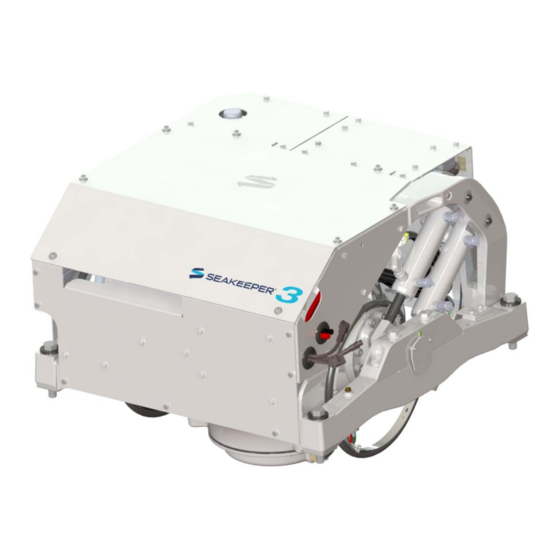
- Page 3 A Seakeeper 3 consists of a Gyro assembly, a CAN communications cable, and a Display. Figure 1 illustrates the interconnection of these components and their interface with the boat.
- Page 4 +/- 70 degrees about this position. The amount of torque that the Seakeeper exerts on a boat’s hull to counter the wave induced roll is directly proportional to the precession rate. The further the Seakeeper is from vertical (zero degrees) the lower the anti-roll torque.
- Page 5 There is a large torque about the gimbal axis when the Seakeeper is precessing. Seakeeper cover panels are provided to prevent personnel or equipment from contacting the Seakeeper while it is in operation. These covers should not be stood on, or have anything placed on top. The covers should always be in place during operation.
- Page 6 This foundation transfers the loads that the Seakeeper produces to the hull structure. An active hydraulic brake mechanism is located on the Seakeeper assembly to regulate the Seakeeper’s precession motions about the gimbal shaft. It includes two hydraulic cylinders and a hydraulic manifold.
- Page 7 1.2 Display The display shown below is the user interface to the Seakeeper 3 and should be mounted at the primary helm station. It is used to start, operate, monitor and shutdown the Seakeeper. Sensors, alarms and shutdowns are provided to allow unattended operation.
- Page 8 1.3 Drive Box The glycol/water mix that cools the Seakeeper is also circulated through a cold plate inside the Drive Box to remove heat from high-power electronic components. The Motor Drive Box contains an electrical hazard and the cover should not be removed while the flywheel is spinning and the DC input voltage is present.
- Page 9 Locking solenoids are installed in the circuit to lock the Seakeeper so it cannot precess if there is a leak in the circuit or a mechanical problem with the Seakeeper.
- Page 10 The heated fluid then passes through a heat exchanger that has seawater on the cold side. The seawater pump output will operate for two minutes after the Seakeeper is turned on. During operation, the seawater pump output is turned on and off based on the temperature of the Seakeeper.
- Page 11 Display Screens: Overview 1) When 12 VDC power is applied to the Seakeeper, the display will power up and initialize. The splash screen will be displayed. 2) After the display has initialized, the home screen will be displayed.
- Page 12 Section 2: SYSTEM OPERATION Seakeeper Stabilize On/Off. The button will change from grey (Stabilize Off) to blue (Stabilize On) Home screen view. These buttons toggle home screen between the Roll Angle Gauge and the Roll Angle Graph as shown below.
- Page 13 OPERATION MANUAL SEAKEEPER 3 90379 3 of 10 Section 2: SYSTEM OPERATION The menu bar is used to navigate between pages. From left to right, the available pages are home, settings, information, service and alarm history. The selected page is highlighted in blue on the menu bar.
- Page 14 Change the units of the temperatures displayed on the service page between degrees Celsius and degrees Fahrenheit. The selected units are colored blue. 6) The information page displays the Seakeeper model, Seakeeper serial number, Seakeeper software versions, RUN hours, and SEA hours, and other information...
- Page 15 7) The service page displays operating information from the Seakeeper. 8) The alarm history page shows what alarms have occurred in the past and the associated run hours. The scroll bar is used to move up and down through the list.
- Page 16 2) When the low DC power is turned on the Display will initialize and the Home screen will appear. To turn the Seakeeper on, press the On/Off button, the button will turn blue. The progress bar will appear and indicate how soon the Seakeeper will be available for stabilization.
- Page 17 Section 2: SYSTEM OPERATION Stabilization To stabilize the boat after Seakeeper is on and above the minimum operating speed: 1) Press the stabilize button. The button will turn blue indicating that the Seakeeper is stabilizing the roll motion.
- Page 18 If it is necessary to stop Seakeeper motion for any reason press the stabilize button. The stabilize button will turn grey indicating that the Seakeeper is locked. Never attempt to work on the Seakeeper until the flywheel has stopped spinning.
- Page 19 2) Once the vessel is secured in the slip, switch the high current and low current DC power to the Seakeeper off. The flywheel will continue to spool down to zero rpm. This can take 8+ hours from full speed.
- Page 20 10 of 10 Section 2: SYSTEM OPERATION Speed Adjustment 1) Press the menu button then select the settings screen. 2) Select the desired RPM button to adjust the Seakeeper’s speed. The selected RPM button will turn blue.
- Page 21 12 Volts DC high current powers the Motor Drive Box to drive the motor inside the Seakeeper. These are supplied on Conductors 1 and 2 and Cable 7 which are shown on Seakeeper drawing 90377, Cable Block Diagram. The Motor Drive Box contains a voltage hazard and the cover should not be removed while the flywheel is spinning or the DC input voltage is present.
- Page 22 VDC high current is turned back on. Alarms The Seakeeper issues an alarm when it detects a malfunction that could cause damage or erratic operation. When an alarm occurs, the Seakeeper will stop and an alarm message is shown on the Display.
- Page 23 Document #: Rev: Page: OPERATION MANUAL SEAKEEPER 3 90379 3 of 4 Section 3: POWER FAILURES, ALARMS, AND TROUBLESHOOTING A view of a typical Alarm screen. To reset the Alarm press the Reset Alarm button...
- Page 24 MANUAL SEAKEEPER 3 90379 4 of 4 Section 3: POWER FAILURES, ALARMS, AND TROUBLESHOOTING Alarm History The alarm history page on the Display shows the recent alarms and warnings. The alarms are in chronological order starting with the most recent. Warnings included in the history page are for issues that do not affect gyro operation.
- Page 25 Scheduled Maintenance to keep the Seakeeper running trouble-free. If the Seakeeper is installed in a wet space, efforts should be made to keep the Seakeeper free of salt residue from either condensation or direct exposure to salt spray. If exposed, a regular wipe down with mild soap and water with a rinse will help limit corrosion and keep the Seakeeper assembly in good cosmetic condition.
- Page 26 Rev: Page: OPERATION MANUAL SEAKEEPER 3 90379 2 of 3 Section 4: MAINTENANCE 4.4 SCHEDULED MAINTENANCE TABLE The following pages contain the scheduled maintenance table organized by systems: Mechanical, Hydraulic, Cooling, and Electrical. Scheduled maintenance is not covered under warranty.
- Page 27 Product: Document #: Rev: Page: OPERATION MANUAL SEAKEEPER 3 90379 3 of 3 Section 4: MAINTENANCE SYSTEM / COMPONENT TASK INTERVAL PARTS / SPECIAL TOOLS Inspect at 12 Hydraulic hand pump kit, Replace brake bushings, Months or 1000...
- Page 28 24 months from date the product put into service, which shall conclusively be presumed to be the date of sale of a vessel, on which a SEAKEEPER product is installed, to a retail customer or date put into service on an existing vessel (refit).
- Page 29 Buyer/User, with written specifications of the claimed defect. If a warranty claim is valid, SEAKEEPER, INC. will repair or replace the Product, or part of the Product, proven to be defective, at its sole discretion, in a timeframe provided by SEAKEEPER, INC., on a reasonable best effort...
- Page 30 Except where otherwise expressly agreed, all patterns, tools, jigs and fixtures, drawings, designs, software and other materials and data developed, fabricated by Seakeeper shall be and shall remain Seakeeper's property. Except as specifically provided for in the order, Buyer shall have no right in any technical data, Intellectual Property Rights, and computer software associated with the order.
- Page 31 MANUAL SEAKEEPER 3 90379 1 of 3 Section 6: SEAKEEPER SPECIFICATIONS Seakeeper 3 Specifications & Summary Seakeeper 3 Rated RPM 8,450 RPM Angular Momentum at Rated RPM 3,000 N-M-S Anti-Rolling Torque at Rated RPM 7,854 N-M Spool-up Time to Rated Speed...
- Page 32 Cover Subsystems. Installation Location The Seakeeper is a torque device and does not have to be installed in a specific hull location or on the centerline. However, the Seakeeper should not be installed forward of the longitudinal center of gravity in a planing vessel.
- Page 33 The Seakeeper controller sends sensor values and alarm information to the display and also locks the brake and shuts down the motor drive in the event of an alarm condition. Seakeeper operating history during faults or alarms is recorded in the controller’s memory for subsequent recall if service is needed.
Need help?
Do you have a question about the 3 and is the answer not in the manual?
Questions and answers
service manual for a sea keeper 3