Seakeeper 3 Installation Manual
Hide thumbs
Also See for SEAKEEPER 3:
- Operation manual (34 pages) ,
- Quick start manual (5 pages) ,
- Installation manual (39 pages)
Table of Contents
Advertisement
INSTALLATION
MANUAL
SEAKEEPER 3
INSTALLATION MANUAL
Contents:
Section 1 – Mechanical Installation
Section 2 – Electrical Installation
Section 3 – Cooling Installation
Section 4 – Startup
Section 5 – Installation Checklist and Required Supplies
CALIFORNIA, MARYLAND, 20619, U.S.A
E-MAIL: customerservice@seakeeper.com
Product:
SEAKEEPER 3
JUNE 2018
44425 PECAN COURT, SUITE 151
PHONE: 410-326-1590
FAX: 410-326-1199
Document #:
Rev:
90378
4
Advertisement
Table of Contents

Subscribe to Our Youtube Channel
Related Manuals for Seakeeper SEAKEEPER 3


Summary of Contents for Seakeeper SEAKEEPER 3
- Page 1 Product: Document #: Rev: INSTALLATION MANUAL SEAKEEPER 3 90378 SEAKEEPER 3 INSTALLATION MANUAL JUNE 2018 Contents: Section 1 – Mechanical Installation Section 2 – Electrical Installation Section 3 – Cooling Installation Section 4 – Startup Section 5 – Installation Checklist and Required Supplies 44425 PECAN COURT, SUITE 151 CALIFORNIA, MARYLAND, 20619, U.S.A...
- Page 2 INSTALLATION MANUAL JUNE 2018, Revision 4...
- Page 3 This document is intended to give details and guidance to a boat builder or equipment installer to install the Seakeeper 3. The Seakeeper 3 is capable of producing loads up to 8.60KN (1,934 lbs.) at each of the four mounts and careful consideration should be given to foundation design to insure it is capable of transferring these loads into the hull.
- Page 4 While handling / installing the Seakeeper assembly, do not allow electrical fittings that exit bottom of the Seakeeper enclosure to come in contact with any surface or object as this could damage the fittings and potentially affect the vacuum integrity of the enclosure.
- Page 5 Document #: Rev: Page: INSTALLATION MANUAL SEAKEEPER 3 90378 3 of 15 Section 1: MECHANICAL INSTALLATION VIEWS SHOWING RECOMMENDED CLEARANCES AROUND THE SEAKEEPER FOR USE OF HANDTOOLS, EASE OF MAINTENANCE, INSTALLATION, AND PROPER OPERATION. FIGURE 2 – INSTALLED SEAKEEPER CLEARANCE CONSIDERATIONS...
- Page 6 90378 4 of 15 Section 1: MECHANICAL INSTALLATION FIGURE 3 – BEAMS CLEARANCE CONSIDERATIONS Refer to Figure 3 for recommended clearances to transverse or longitudinal beams. Clearances aft of the Seakeeper are shown to provide access for regular scheduled maintenance.
- Page 7 Seakeeper noise has been measured under steady state conditions (no wave load) in Seakeeper's lab and in our test boat. The steady state noise is typically in the range of 64-66 dBC un-weighted. As the frequencies emitting the highest sound pressures are low (like other marine machinery), it is recommended that the Seakeeper be installed in a machinery space that is already treated with soundproofing.
- Page 8 2) Remove covers, electrical components, display, cables, and misc. items and set aside. 3) Remove packing materials that secure Seakeeper assembly inside the crate. 4) Attach a spreader bar (Seakeeper #80283) to the two lifting eyes located on the top of the Seakeeper enclosure.
- Page 9 Longitudinal Bolt-In Installation 1.4.1 Check and Preparation of Hull Structure The Seakeeper 3 can be affixed to the hull structure using two methods 1) Longitudinal Beam Bolt-In installation or 2) Transverse Beam Bolt-In installation. Neither option affects the operation of the Seakeeper. However, one option might ease the installation process or allow for a larger service envelope.
- Page 10 8 of 15 Section 1: MECHANICAL INSTALLATION FIGURE 5 – EXPLODED VIEW OF INSTALLATION FIXTURE CAUTION: Tight clearances from cable guide bands to hull structure. See above figure for dimensions and reference Seakeeper drawing NO. 90374 for complete Seakeeper 3 envelope.
- Page 11 1.4.2 Transfer of Holes to Boat Structure 1) Lower assembled fixture onto hull structure. The four areas where the feet of the Seakeeper will rest should be coplanar to within .06” (1.5 mm). See Figure 10. 3) Align fixture in desired location and transfer holes from fixture plate to the hull structure.
- Page 12 Apply a small bead (approximately 4 mm wide) of sealant (silicone or caulk) between both mating surfaces of each isolation gasket where it contacts the beam and the Seakeeper. This will prevent water from wicking between the parts and setting up corrosion. Check isolation gasket alignment by test fitting bolts without any obstructions.
- Page 13 Transverse Bolt-In Installation 1.5.1 Check and Preparation of Hull Structure The Seakeeper 3 can be affixed to the hull structure using two methods 1) Longitudinal Beam Bolt-In installation or 2) Transverse Beam Bolt-In installation. Neither option affects the operation of the Seakeeper. However, one option might ease the installation process or allow for a larger service envelope.
- Page 14 12 of 15 Section 1: MECHANICAL INSTALLATION FIGURE 5 – EXPLODED VIEW OF INSTALLATION FIXTURE CAUTION: Tight clearances from cable guide bands to hull structure. See above figure for dimensions and reference Seakeeper drawing NO. 90374 for complete Seakeeper 3 envelope.
- Page 15 1.5.2 Transfer of Holes to Boat Structure 5) Lower assembled fixture onto hull structure. The four areas where the feet of the Seakeeper will rest should be coplanar to within .06” (1.5 mm). See Figure 10. 7) Align fixture in desired location and transfer holes from fixture plate to the hull structure.
- Page 16 Apply a small bead (approximately 4 mm wide) of sealant (silicone or caulk) between both mating surfaces of each isolation gasket where it contacts the beam and the Seakeeper. This will prevent water from wicking between the parts and setting up corrosion. Check isolation gasket alignment by test fitting bolts without any obstructions.
- Page 17 5) Remove the Seakeeper unit using a spreader bar. 1.6.2 Disposal DO NOT disassemble the Seakeeper to a greater degree than necessary for removal from the boat. DO NOT dispose of a Seakeeper unit in a landfill. The unit must be shipped back to Seakeeper.
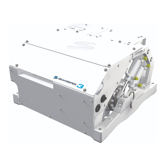
- Page 18 Mounting Details SEAKEEPER 3, Front Oblique View SEAKEEPER 3, Rear Oblique View 12VDC Power Input Cable SW Pump DC Power Cable Terminator, Female Tee Adapter Touch Screen Display 2ft Cable 10m Cable FIGURE 1 – ELECTRICAL EQUIPMENT FOR SEAKEEPER 3...
- Page 19 Precautions • Each item of electrical equipment has specific mounting instructions. These instructions should be followed to insure proper function of the Seakeeper. Do NOT move Seakeeper mounted components from their locations or incorrect Seakeeper operation will result. 1. TOUCH DISPLAY MOUNTING INSTRUCTIONS, SURFACE MOUNT a.
- Page 20 LOW CURRENT 12VDC INPUT POWER CONNECTOR (LARGER) FIGURE 2 – SEAKEEPER 3 DC POWER INPUT & OUTPUT CONNECTIONS 1. HIGH CURRENT 12V POWER INPUT a. HIGH CURRENT 12 VDC POWER SOURCE REQUIREMENTS i. Source: Battery Bank, 12 VDC, Marine, Deep Cycle ii.
- Page 21 If the 2 AWG high current 12V power input conductors or shortened or lengthened, use heavy-duty eyelet (closed end) terminal such as Molex 19221-0235 and follow instructions on Seakeeper drawing 90377, SK3 Cable Block Diagram, sheet 2. viii. The bare wire strands should extend fully into the barrel of the heavy-duty eyelet and be crimped in two places if possible then sealed with double-wall heat shrink tubing.
- Page 22 Reversing polarity on the DC power input to the Seakeeper can result in damaging the electronics in the control system. i. Install Seakeeper provided DC Power Input Cable, P/N: 20248 as CABLE 7 to battery bank. ii. Connect plus conductor (B+, Red) through dedicated over-current protection device (customer supplied).
- Page 23 Locate CABLE 5 for DC power output to the customer supplied Seawater Pump, 2 x 16AWG (2 x 1.5 mm CSA) cable, 16 ft (5m) length, Seakeeper supplied ii. Pumps rated at 12 VDC, 3 Amps max., Customer-supplied, must be configured with a Deutsch DT series, 2-pin receptacle to mate with the connector shown in Figure 7.
- Page 24 7 of 12 Section 2: ELECTRICAL INSTALLATION iii. CABLE 5 must be routed and installed in the vessel from the Seakeeper (male end) to the DC Seawater Pump (female end). (See Figure 7.) FIGURE 7 – CABLE 5, SEAWATER PUMP DC OUTPUT POWER CABLE iv.
- Page 25 Product: Document #: Rev: Page: INSTALLATION MANUAL SEAKEEPER 3 90378 8 of 12 Section 2: ELECTRICAL INSTALLATION c. SEAWATER PUMP POWER CONNECTION INSTRUCTIONS FOR OTHER VOLTAGE OR OTHER CURRENT i. If the customer-supplied Seawater Pump is not rated for 12VDC, 3A or less, the CABLE 5 output may be used to switch a customer-supplied relay.
- Page 26 Product: Document #: Rev: Page: INSTALLATION MANUAL SEAKEEPER 3 90378 9 of 12 Section 2: ELECTRICAL INSTALLATION Seakeeper included Seawater Pump 3A fuse EATON BUSSMANN ATC-3 FIGURE 10 – SEAKEEPER INCLUDED SEAWATER 3A FUSE LOCATION...
- Page 27 Install CABLE 6 (4AWG or 25 mm , Customer Supplied) from the M6 brass ground stud on the rear brace to a suitable vessel ground. Note: ONLY USE THIS LOCATION FOR GROUNDING THE SEAKEEPER TO THE VESSEL GROUND. GROUND STUD FIGURE 11 –...
- Page 28 .58 inch (14.8mm). b. CABLE 3 must be routed and installed in the vessel from the Seakeeper (female end) to the Tee Adapter (male end) at the Operator Station.
- Page 29 Product: Document #: Rev: Page: INSTALLATION MANUAL SEAKEEPER 3 90378 12 of 12 Section 2: ELECTRICAL INSTALLATION Display Installation Template The following template is for mounting; before using this template, measure to ensure that the shown size is actual. DISPLAY MOUNTING TEMPLATE...
- Page 30 1 of 5 Section 3: COOLING INSTALLATION Introduction The Seakeeper 3 is shipped with the cooling circuit filled and ready for use. Only a quick confirmation of glycol level is required. Reference Drawings 90388 Seakeeper 3 Hardware Scope of Supply...
- Page 31 Product: Document #: Rev: Page: INSTALLATION MANUAL SEAKEEPER 3 90378 2 of 5 Section 3: COOLING INSTALLATION FIGURE 2 – SEAKEEPER 3 COOLING COMPONENTS...
- Page 32 Seakeeper installations should be checked to be within the flow requirements while vessel is at speed. Flows higher than 6 GPM (22.7 LPM) could affect heat exchanger life.
- Page 33 Document #: Rev: Page: INSTALLATION MANUAL SEAKEEPER 3 90378 4 of 5 Section 3: COOLING INSTALLATION Mix 50% ethylene glycol with 50% distilled water in a clean container. Refer to Table 1 or glycol manufacturer’s literature for freezing points. It is required that ethylene glycol with corrosion inhibitors be used.
- Page 34 Connect seawater discharge (upper hose barb) to overboard drain. Use the same practices as other below waterline seawater plumbing. In addition to initial operation at dock, new Seakeeper installations should be checked for minimum 2 GPM (7.6 LPM) flow while vessel is at speed and when backing down. If no other method of confirming flow is available, discharge line may be temporarily diverted to a bucket.
- Page 35 2) Supply 12 VDC 100A to Motor Drive Box at customer supplied electrical disconnect. 3) If seawater pump for the Seakeeper is not supplied though cable from Motor Drive Box, turn on the boat’s DC dedicated circuit breaker that supplies power to the seawater pump.
- Page 36 Seakeeper should be switched to the OFF position. The Seakeeper will continue to spool down to zero rpm. No cooling is required during this time. Note the Seakeeper 3 will take 8+ hours to coast down to zero rpm from full speed. When the flywheel has...
-
Page 37: Installation Checklist
Seakeeper supplied foundation bolts torqued to specification Clearances around Seakeeper meet specifications and no obstructions are within the Seakeeper envelope Electrical Checklist (reference Seakeeper Drawing 90257 & Installation Manual Section 2) Mount Components Display (near helm) Connect Seakeeper and Customer Supplied Cables ... - Page 38 Follow instruction in Section 4.1 of Installation Manual to turn off the Seakeeper DC power and seawater pump may be turned off after the Seakeeper is turned off by placing the Seakeeper in LOCK mode and Turning the Seakeeper off ...
- Page 39 Spreader bar for lifting the Seakeeper Mechanical Hose clamps for seawater plumbing to 3/4" (19 mm) Cooling hose barb (2 per hose barb) M6 terminal lug for grounding Seakeeper at rear brace 2.3.1 Electrical Cable, 4 AWG, for grounding Seakeeper at rear brace 2.3.1...
Need help?
Do you have a question about the SEAKEEPER 3 and is the answer not in the manual?
Questions and answers