Advertisement
Quick Links
Advertisement

Subscribe to Our Youtube Channel
Related Manuals for Seakeeper 26000 GYRO


Summary of Contents for Seakeeper 26000 GYRO
- Page 1 INSTALLATION MANUAL MODEL 26000 GYRO Rev 2 July 2013 ...
- Page 2 THIS PAGE INTENTIONALLY LEFT BLANK...
- Page 3 Product: Document #: Rev: INSTALLATION MANUAL MODEL 26000 GYRO 90183 2 MODEL 26000 GYRO INSTALLATION MANUAL JULY 2013 Contents: Section 1 – Mechanical Installation & PC‐120 Guide Section 2 – Electrical Installation & Power Configurations for Seakeeper Gyro Stabilizers Section 3 – Cooling Installation Section 4 – Startup Section 5 – Installation Checklist and Required Supplies 44425 PECAN COURT, SUITE 151 CALIFORNIA, MARYLAND, 20619, U.S.A PHONE: 410‐326‐1590 FAX: 410‐326‐1199 E‐MAIL: customerservice@seakeeper.com ...
- Page 4 THIS PAGE INTENTIONALLY LEFT BLANK...
- Page 5 1.0 Introduction This document is intended to give details and guidance to a boat builder or equipment installer to install the Seakeeper, Inc. Model 26000 Stabilizing Gyro. There are two methods of installing the Model 26000 gyro: 1) Saddle Installation – this is used on fiberglass constructed hulls. 2) Bolt‐In Installation – this is used for metal constructed hulls. It is assumed that the installer is familiar with bonding using high strength adhesives or bolting and has ...
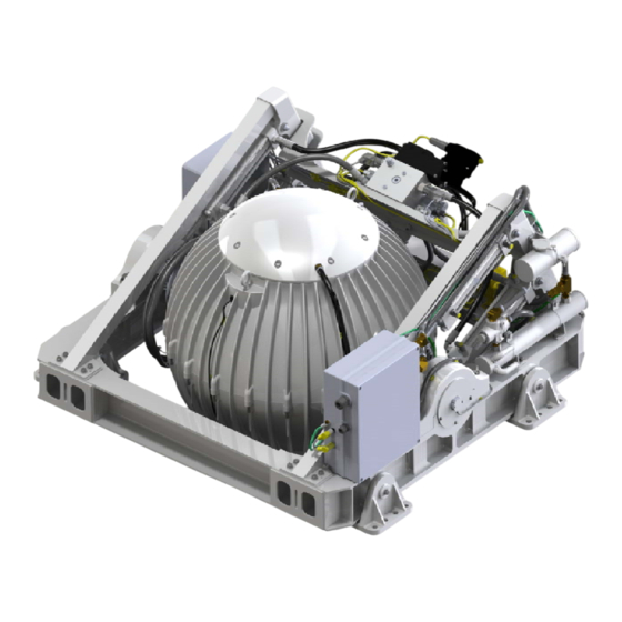
- Page 6 Product: Document #: Rev: Page: INSTALLATION MANUAL MODEL 26000 GYRO 90183 2 2 of 23 Section 1: MECHANICAL INSTALLATION FIGURE 1 – MODEL 26000 GYRO 1.1 Precautions Gyro flywheel is supported by precision bearings. Make certain while unpacking and lifting gyro assembly to NOT drop or impart mechanical shock as damage to bearings could result. While handling / installing gyro assembly, protect exposed hydraulic brake cylinder rods (See Figure 1 above) from scratches or damage as this could lead to premature seal failure and oil leaks. While handling / installing gyro assembly, do not allow electrical fittings that exit bottom of gyro enclosure to come in contact with any surface or object as this could damage the fittings and potentially affect the ...
- Page 7 Product: Document #: Rev: Page: INSTALLATION MANUAL MODEL 26000 GYRO 90183 2 3 of 23 Section 1: MECHANICAL INSTALLATION 1.2 Selection of Gyro Installation Location Selection of mounting location of gyro should consider the following desirable features: The gyro must be installed aft of amidships to minimize high acceleration loadings due to hull/wave impacts during operation at high speed or in large waves. Removable overhead access or sufficient clearance for removal / re‐installation of gyro for overhaul in future years. ...
- Page 8 Noise/Soundproofing/Ventilation Gyro noise has been measured under steady state conditions (no wave load) in Seakeeper's test facility. The steady state noise is typically in the range of 72‐74 dB unweighted. As the frequencies emitting the highest sound pressures are low (like other marine machinery), it is recommended that the gyro be installed in a cage in a ...
- Page 9 Product: Document #: Rev: Page: INSTALLATION MANUAL MODEL 26000 GYRO 90183 2 5 of 23 Section 1: MECHANICAL INSTALLATION 1.3 Selection of Installation Method The Model 26000 gyro can be affixed to the hull structure using two methods 1) Use saddle installation or 2) bolt‐ in installation. See figures below. Option 1 would be most commonly used on a hull constructed of glass reinforced plastic (GRP) or fiberglass. For this option, four 16 inch (406 mm) long by 8 inch( (203 mm) deep saddles are bonded to properly spaced and prepared structural members that are an integral part of the hull structure. Seakeeper recommends using a structural adhesive with a lap shear strength of 2000 psi (13.8 MPa) or greater. Careful consideration should be ...
- Page 10 exercised by the installer while selecting the appropriate adhesive. Compatibility with the gyro’s cast aluminum A356‐ T6 saddles, hull structure and pot life are three important factors to consider. Option 2 would be applied on a hull or gyro support structure constructed of steel or aluminum. The four isolation mounts would fasten directly to hull structure using 32x M16 or 5/8 inch fasteners. Depending on access around the boat’s structure blind threaded holes or thru‐bolting can be utilized. 1.4 Unpacking Crate 1) Reference Seakeeper Drawing No. 90155, Model 26000 Gyro Hardware Scope of Supply for items that ship with the gyro. 2) Reference Seakeeper Document No. 90203, Model 26000 Crate Unpacking Instructions for information on disassembling crate. 3) Remove angles used for installation fixtures – take care not to damage as any distortion of angles could result in foundation alignment problems. 4) Remove saddles (if applicable) electrical components, cables, and misc. items contained in boxes and set aside. 5) Remove 16 x lag bolts that fasten gyro to crate base. ...
- Page 11 / installer to lay‐up and adjust the foundation dimensions to create a low‐clearance fit between the gyro foundation saddles and the hull structure. Shear strength of the adhesive will be maximized if the cured thickness between the vessel structure and gyro saddles is at the thinner end of the adhesive manufacturer’s recommended range. Therefore, the fixture should be used to confirm that the overall dimensions of the foundations are square and level and that the adhesive gap is within Seakeeper’s maximum recommended thickness of .13” or 3mm. Note: Do NOT use the installation fixture to establish gyro envelope dimensions. Refer to Drawing No. 90137 for envelope dimensions. A 3‐D model of the gyro is available on the Seakeeper website (www.seakeeper.com) ...
- Page 12 Product: Document #: Rev: Page: INSTALLATION MANUAL MODEL 26000 GYRO 90183 2 8 of 23 Section 1: MECHANICAL INSTALLATION FIGURE 4 – EXPLODED VIEW OF SADDLE INSTALLATION FIXTURE ...
- Page 13 Product: Document #: Rev: Page: INSTALLATION MANUAL MODEL 26000 GYRO 90183 2 9 of 23 Section 1: MECHANICAL INSTALLATION FIGURE 5 – NOTICE FOR CHECKING SQUARE OF ASSEMBLY ...
- Page 14 Product: Document #: Rev: Page: INSTALLATION MANUAL MODEL 26000 GYRO 90183 2 10 of 23 Section 1: MECHANICAL INSTALLATION FIGURE 6 – SADDLE INSTALLATION FIXTURE ON NOTIONAL HULL STRUCTURE ...
- Page 15 Product: Document #: Rev: Page: INSTALLATION MANUAL MODEL 26000 GYRO 90183 2 11 of 23 Section 1: MECHANICAL INSTALLATION 1.5.2 Fiberglass Hull Preparation 1) Position installation fixture (Fig 7) on hull girders noting recommended clearances for maintenance from Figure 2. Check that the screws fastening the saddles to the installation fixture are tight (Fig 5). ...
- Page 16 FIGURE 9 – COPLANAR PROPERTIES OF FOUNDATION 4) Thoroughly clean with alcohol or acetone all areas (highlighted in brown, Fig 9) of girders to be bonded to remove any contaminates. Use new paper towels for cleaning, not shop rags. 5) Remove all paint and gel‐coat from bond surfaces so that adhesive will bond directly to laminate fibers and resin as shown in Figure 7. 6) Thoroughly sand girder bond surfaces with 80 grit sandpaper. (IMPORTANT – BOND STRENGTH MAY BE REDUCED IF THIS STEP IS SKIPPED.) 7) Wipe surfaces clean from dust with alcohol or acetone using new paper towels, not shop rags. 8) Re‐position installation fixture on girders and double‐check that the adhesive gap is within the adhesive manufacturer’s maximum recommended thickness. (Note gap will be larger due to absence of gel‐coat.) Seakeeper recommends a maximum gap of 3mm if using Plexus MA590. ...
- Page 17 2 13 of 23 Section 1: MECHANICAL INSTALLATION 9) Lift installation fixture clear of foundation. Apply Seakeeper provided adhesive backed foam strips at the eight locations shown (each end of four saddles) in Figure 10 below. These strips are to serve as a dam to minimize adhesive escaping out the ends of ...
- Page 18 Product: Document #: Rev: Page: INSTALLATION MANUAL MODEL 26000 GYRO 90183 2 14 of 23 Section 1: MECHANICAL INSTALLATION 1.5.3 Gyro Saddle Preparation 1) Ensure that screws fastening saddles to the installation fixture are tight (Fig 5). 2) Check that each saddle contains 4 plastic screws which will insure an adhesive gap of .080” (2 mm) on top surface of hull as shown in Figure 11. Plastic Screws 3) Thoroughly clean with alcohol or acetone the inside surfaces of gyro foundation saddles to remove any contaminates as shown in Figure 11. Use new paper towels for cleaning, not shop rags. Clean inside ...
- Page 19 Product: Document #: Rev: Page: INSTALLATION MANUAL MODEL 26000 GYRO 90183 2 15 of 23 Section 1: MECHANICAL INSTALLATION 1.5.4 Bonding Saddles to Hull Note: If using Plexus MA590 adhesive, the gyro saddles should be installed when PC‐120 is confirmed dry. 1) Assemble Plexus cartridge into either the manual or pneumatic gun as shown. Remove cap on cartridge and attach mixing tip. For pneumatic gun, start with low air pressure and increase until desired flow rate is achieved. ...
- Page 20 Product: Document #: Rev: Page: INSTALLATION MANUAL MODEL 26000 GYRO 90183 2 16 of 23 Section 1: MECHANICAL INSTALLATION 5) Apply large bead of Plexus adhesive to the hull structure as shown in the figure to the right. Apply approximately 1 ½ cartridges at each of the four locations. Work deliberate and fast as it takes some time ...
- Page 21 3) Install Seakeeper supplied M16 fasteners as shown in figure to right– apply a moderate coat of nickel based anti‐seize compound to the threads of each bolt prior to installation. Torque all fasteners to 100 ft‐lbs (136 N‐m). 5) Apply a small bead of sealant (silicone or caulk) around the perimeter of each ...
- Page 22 Product: Document #: Rev: Page: INSTALLATION MANUAL MODEL 26000 GYRO 90183 2 18 of 23 Section 1: MECHANICAL INSTALLATION 6) Verify that safety wire is intact and bolts are not loose in Isolation Mount Pin Retainer Bolts, 8 places. 7) Proceed to electrical and cooling portion of the installation. ...
- Page 23 inch (3 mm) to minimize potential distortion of gyro support frame when installed. (Similar to Figure 9). Seakeeper provides an installation fixture assembly, P/N 90089, that contains four plates that mimic the mating surfaces of the four isolation mounts located on the gyro’s foundation. These plates have 8 holes located at the same centers as the holes in the isolation mounts. These smaller holes can be used to locate the holes in the ship’s structure through use of a transfer punch. The fixture locates the hole patterns at the proper spacing both in the ...
- Page 24 Product: Document #: Rev: Page: INSTALLATION MANUAL MODEL 26000 GYRO 90183 2 20 of 23 Section 1: MECHANICAL INSTALLATION FIGURE 14 – NOTICE FOR CHECKING SQUARE OF ASSEMBLY ...
- Page 25 Product: Document #: Rev: Page: INSTALLATION MANUAL MODEL 26000 GYRO 90183 2 21 of 23 Section 1: MECHANICAL INSTALLATION 1.6.2 Transfer of Holes to Foundation 1) Lower assembled fixture onto gyro foundation. The four areas where the isolation mounts will rest should be coplanar to within 1/8” (3mm). See Figure 9. Do not use the fixture to check co‐planarity as it is not stiff enough. 3) Align fixture in desired location and transfer holes from fixture plate to the foundation structure. A transfer punch is recommended for this step. Note that holes in fixture plate are ø.257 (6.5mm). 4) Remove fixture and drill holes in foundation at marked locations to mate with holes in gyro isolation mounts. A ø.689 inch ...
- Page 26 3) Install Seakeeper supplied M16 fasteners as shown in figure to right– apply a moderate coat of nickel based anti‐seize compound to the threads of each bolt prior to installation. 4) Torque all fasteners to 100 ft‐lbs (136 N‐m). 5) Apply a small bead of sealant (silicone or caulk) around the perimeter of each ...
- Page 27 Product: Document #: Rev: Page: INSTALLATION MANUAL MODEL 26000 GYRO 90183 2 23 of 23 Section 1: MECHANICAL INSTALLATION 6) Verify that safety wire is intact and bolts are not loose in Isolation Mount Pin Retainer Bolts, 8 places. 7) Proceed to electrical and cooling portion of the installation. Doc # 90213 Plexus PC‐120 Application Instructions ...
- Page 28 THIS PAGE INTENTIONALLY LEFT BLANK...
- Page 29 INSTRUCTIONS Product: All Document #: 90213 Process: Plexus PC‐ 120 Application Instructions Rev.: 1 Process Description: Instructions for use of surface conditioner Page 1 of 4 What is Plexus PC‐120? Plexus PC‐120 is a dual function primer/conditioner designed to clean surface contamination and leave a thin coating of primer on specific metal surfaces. Although designed specifically for cleaning and priming of Aluminum and Stainless Steel, PC‐120 can be used to clean other surfaces in special situations. Contact Plexus Technical Service for recommendations on any surface other than Aluminum or Stainless Steel. Plexus PC‐120 works by: Cleaning the surface of contamination using Isopropyl Alcohol to “lift” machine oils and other contamination. Depositing a thin Phosphate based coating to retard corrosion. Leaving a light “pink” color to assist in determining what areas have, and have not, been treated with PC‐120. How should PC‐120 be used? PC‐120 can be brushed, wiped or sprayed onto the surface being primed. ...
- Page 30 INSTRUCTIONS Page 2 of 4 Product: ALL Document #: 90213 Process: Plexus PC‐ 120 Application Instructions Rev.: 1 1) Using too much PC‐120 Only a very thin coat should be left on the metal. You should be able to see a slight “pink” cast as illustrated below. Too Much PC‐120 Correct Amount 2) Not removing oils once primed Wipe the surface with a dry rag The solvents in PC‐120 will clean and “lift” most machining oils, but if the metal isn’t wiped clean of these oils then they will be deposited right back onto the metal surface when the solvent in PC‐120 evaporates! ...
- Page 31 INSTRUCTIONS Page 3 of 4 Product: ALL Document #: 90213 Process: Plexus PC‐ 120 Application Instructions Rev.: 1 3) Not abrading corroded surfaces As good as PC‐120 is, it can’t help bonding performance if applied to a surface that is already corroded! Any surface that shows signs of corrosion should be cleaned by sanding or wire brushing to remove any scale or corrosion. After removal of corrosion then treat the surface with PC‐120 as you normally would. 4) Using PC‐120 past it’s shelf life When stored under normal conditions PC‐120 has a shelf life of 12 months in an unopened, original container. PC‐120 bottles are marked with a lot number that is a simple 8 digit code that gives you the date of manufacture. o “807241” for example is 2008, 07 month (July), 24th day (the “1” refers to the first batch of PC‐120 made that day). Use the lot number to make sure the material is still within shelf life. Since it contains isopropyl alcohol, PC‐120 should be tightly capped when not in use to stop evaporation. ...
- Page 32 INSTRUCTIONS Page 4 of 4 Product: ALL Document #: 90213 Process: Plexus PC‐ 120 Application Instructions Rev.: 1 Remember these points! To avoid problems with Plexus PC‐120: Don’t use too much PC‐120. Only a thin layer is needed. Use a clean rag to wipe PC‐120 off before it completely dries to remove surface contaminants it has cleaned. Good quality paper towels are a better choice to minimize introduction of contaminates to surface. Any sign of corrosion already on the surface should be removed by abrading BEFORE priming. Check the lot number for the date to make sure the PC‐120 is less than a year old. Questions Please contact Plexus Technical Service at 1‐800‐851‐6692 or info@itwplexus.com ...
-
Page 33: Section 2: Electrical Installation
Product: Document #: Rev: Page: INSTALLATION MANUAL MODEL 26000 GYRO 90183 2 1 of 17 Section 2: ELECTRICAL INSTALLATION Introduction This section for electrical installation explains how to mount the electrical equipment and how to connect the electrical cables. Reference Drawings Reference Work Instructions 90010 Serial Communications 6‐Way Connection Box 020 Installation Instructions, Envelope & Mounting Details 24VDC Power Connector 90155 Model 26000 Gyro Hardware Scope of Supply ... - Page 34 Product: Document #: Rev: Page: INSTALLATION MANUAL MODEL 26000 GYRO 90183 2 2 of 17 Section 2: ELECTRICAL INSTALLATION Electrical Equipment Mounting Precautions Each item of electrical equipment has specific mounting instructions. These instructions should be followed to insure proper function of the Model 26000 Gyro. Do NOT move Gyro Control Box from its location or incorrect Gyro operation will result. 1. COMPACT MOTOR DRIVE BOX MOUNTING INSTRUCTIONS a. M26000 Gyro Compact Motor Drive Box comes from the factory mounted on the Gyro. b. Location: Gyro port Side Beam, forward end. c. Orientation: Rear panel facing Gyro sphere. 2. GYRO CONTROL BOX MOUNTING INSTRUCTIONS a. M26000 Gyro Control Box comes from the factory mounted on the Gyro. b. Location: Gyro starboard Side Beam, aft end. c. Orientation: Rear panel facing Gyro sphere. ...
- Page 35 Electrical Equipment Power Connections 1. 230 VAC POWER SOURCE REQUIREMENTS a. 230 VAC (nominal), 1 Phase, 50/60 Hz, 20 Amps. b. A separate circuit breaker should be used for each Motor Drive Box. 2. COMPACT MOTOR DRIVE BOX AC POWER INPUT CONNECTION INSTRUCTIONS a. Cable: 3 x 10AWG (3 x 6mm CSA), 10’ (3m) length, Seakeeper supplied pre‐installed. i. Locate CABLE 2 for AC power input to the Compact Motor Drive Box at the larger of two cable glands. LARGE CABLE FOR AC POWER INPUT GROUND STUD LOCATION FIGURE 2 – COMPACT MOTOR DRIVE BOX AC POWER INPUT CABLE INTO GLAND FIGURE 3 – CABLE 2 WIRE CONNECTIONS AT AC POWER DISTRIBUTION PANEL ii. Seakeeper uses two types of cable for AC power. One type has black, white, and green wires, and the other type has red, black, and white wires. Determine which cable type is present. iii. Connect 230 VAC wires in CABLE 2 to a 20 Amp, double‐pole Circuit Breaker at an AC power distribution panel or through a customer‐supplied splice box according to Figure 3 above. ...
- Page 36 The Compact Motor Drive Box is grounded to the Gyro frame through the ground stud at the location shown in Figure 2. Do not remove the ground wire from this stud. 3. COMPACT MOTOR DRIVE BOX AC POWER OUTPUT TO SEAWATER PUMP CONNECTION INSTRUCTIONS a. Cable: 3 x 16AWG (3 x 1.5mm CSA) cable, 10’ (3m) length, Seakeeper supplied pre‐ installed b. Pumps rated at 230 VAC, 5 Amps max., Customer‐supplied. ...
- Page 37 c. If the customer‐supplied Seawater Pump is not rated for 230 VAC, the CABLE 8 output may be used to switch a customer‐supplied relay. i. Locate CABLE 8 for AC power output to the Seawater Pump from the Compact Motor Drive Box at the smaller of two cable glands as shown in Figure 4. ii. Seakeeper uses two types of cable for AC power. One type has black, white, and green wires, and the other type has red, black, and white wires. Determine which cable type is present. ...
- Page 38 The recommended wiring is shown in Figure 7. Refer to Figure 5 for Cable 8 wire connections. COMPACT MOTOR DRIVE CABLE 8 3x16AWG or 3x1.5mm CIRCUIT SEAKEEPER SUPPLIED, BREAKER, 5 AMP 3m LENGTH SEAWATER PUMP TB 4 POWER, 208-230 VAC, TB 5 5A, 1Ø, 50/60 Hz...
- Page 39 90183 2 7 of 17 Section 2: ELECTRICAL INSTALLATION 4. 24 VDC POWER SOURCE REQUIREMENTS a. 24 VDC, 10 Amps. b. A separate breaker should be used for each Gyro Control Box. 5. GYRO CONTROL BOX POWER CONNECTION INSTRUCTIONS Reversing polarity on the 24 VDC system to the gyro control box can result in damaging the electronics in the control system. a. 24 VDC, 10 Amps. 2 x 12AWG (3 x 4mm CSA) customer supplied. i. Install Seakeeper provided connector P/N: 30104 (Turck P/N: B4131‐0/13,5) on CABLE 1 using Work Instruction 020 (located at end of section 2). Then connect CABLE 1 to J10 on Gyro Control Box. 3 (24V Rtn) 2 (+24VDC) 1 (not used) FIGURE 8 – SEAKEEPER PROVIDED FIGURE 9 – 24VDC POWER INPUT CONNECTOR 24VDC POWER INPUT CONNECTOR CONTACT ASSIGNMENTS (rear) ...
- Page 40 Product: Document #: Rev: Page: INSTALLATION MANUAL MODEL 26000 GYRO 90183 2 8 of 17 Section 2: ELECTRICAL INSTALLATION Electrical Equipment Signal Connections 1. COMPACT MOTOR DRIVE BOX CABLES a. Signal cables connect to the receptacles on the lower left side of the Compact Motor Drive Box and come installed from the factory as shown in Figure 11. The motor power connector comes from the factory installed on the cable as shown in Figure 12. i. J1: Motor Power, CABLE 10 from Gyro sphere. ii. J2: Drive Control, CABLE 14 from Gyro Control Box. iii. J3: Motor Instrumentation, CABLE 11 from Gyro sphere. ...
- Page 41 Assembly) to 6‐Way Serial Communications Connection Box, Seakeeper supplied, customer installed. 1. See Section 2.4 & 2.5. ix. J9: Alarm Output, CABLE 8 (30182 Cable Assembly) to Alarm & Monitoring System, Seakeeper supplied, FIGURE 13 – GYRO CONTROL BOX customer installed. CONNECTORS 1. See Section 2.3.3. x. J10: 24 VDC Input Power, CABLE 1, customer installed. 1. See Section 2.2.4. ...
- Page 42 AND 0.5 AMP. CONTACTS: FOR ALARM DEVICES. RELAYS, CUSTOMER SUPPLIED GYRO CONTROL BOX CABLE 17 ALARM RESETTABLE 30182 OUTPUT, FUSE, 24V, SEAKEEPER VOLTS-FREE 0.77A @ 60C PROVIDED CONTACT, ALARM ALARM = OUTPUT, CLOSED VOLTS-FREE CONTACT RESETTABLE FUSE, 24V, 0.77A @ 60C USE OF J9-3 &...
- Page 43 Product: Document #: Rev: Page: INSTALLATION MANUAL MODEL 26000 GYRO 90183 2 11 of 17 Section 2: ELECTRICAL INSTALLATION 4. GYRO TO VESSEL GROUND CONNECTION INSTRUCTIONS a. Connect the Gyro foundation to vessel ground. i. Install CABLE 16 (4AWG or 22.0mm , Customer supplied) from one of the available M6 brass ground studs on the Gyro rear brace to a suitable vessel ground. ...
-
Page 44: Operator Station
Product: Document #: Rev: Page: INSTALLATION MANUAL MODEL 26000 GYRO 90183 2 12 of 17 Section 2: ELECTRICAL INSTALLATION Operator Station This section explains the connection between the Operator Station equipment and the Gyro Control Box. Reference Drawing 90174 Model 26000 Gyro Cable Block Diagram 1. DETERMINE LOCATION OF OPERATOR STATION a. The desired location of the Operator Station must be determined with respect to the vessel arrangement. ... - Page 45 Product: Document #: Rev: Page: INSTALLATION MANUAL MODEL 26000 GYRO 90183 2 13 of 17 Section 2: ELECTRICAL INSTALLATION 2. ROUTE SERIAL COMMUNICATIONS CABLE a. The Serial Communications Cable Assembly (20141, CABLE 5) is a 25 meter shielded cable and the smaller connector is a molded plug with maximum outer diameter of .65 inch (16.5mm). b. CABLE 5 must be routed and installed in the vessel from the 6‐Way Connection Box at the Operator Station to the Gyro Control Box. c. If the serial communications cable, 20141 (CABLE 5), is too long for the installation, the overall length may be reduced by removing a section of the cable and inserting a splice box. Connect all conductors and shielding according to Figure 17 below. SERIAL COMMUNICATIONS SPLICE BOX TO 6-WAY...
- Page 46 Product: Document #: Rev: Page: INSTALLATION MANUAL MODEL 26000 GYRO 90183 2 14 of 17 Section 2: ELECTRICAL INSTALLATION Second Operator Station Connection This section explains how to connect the 2 Operator Station Kit. Reference Drawings 90238 2 Operator Station Kit 90175 Model 26000 Gyro with 2 Operator Stations Cable Block Diagram 1. DETERMINE LOCATION OF 2 OPERATOR STATION a. The desired location of the 2 Operator Station must be determined with respect to the Operator Station and the vessel arrangement. b. Typical locations include: i. Flybridge ii. Engine room 2. DETERMINE CABLING ARRANGEMENT a. Figure 18 below shows the entire serial communications link for 2 Operator Stations. The Serial Comms Terminator must be installed on the Serial Comms 6‐Way Connection ...
-
Page 47: Work Instructions
Product: Document #: Rev: Page: INSTALLATION MANUAL MODEL 26000 GYRO 90183 2 15 of 17 Section 2: ELECTRICAL INSTALLATION 3. ROUTE 2 OPERATOR STATION CABLE a. A second Serial Communications Cable Assembly (20141, CABLE 22) is a 25 meter shielded cable and the smaller connector is a molded plug with maximum outer diameter of .65 inch (16.5mm). ... - Page 48 THIS PAGE INTENTIONALLY LEFT BLANK...
- Page 49 Product: Document #: Rev: Page: INSTALLATION MANUAL MODEL 26000 GYRO 90183 2 16 of 17 Section 2: ELECTRICAL INSTALLATION SURFACE MOUNT TEMPLATE ...
- Page 50 THIS PAGE INTENTIONALLY LEFT BLANK...
-
Page 51: Flush Mount Template
Product: Document #: Rev: Page: INSTALLATION MANUAL MODEL 26000 GYRO 90183 2 17 of 17 Section 2: ELECTRICAL INSTALLATION FLUSH MOUNT TEMPLATE ... - Page 52 THIS PAGE INTENTIONALLY LEFT BLANK...
- Page 53 Product: M7000A, M8000, WORK M21000, M21000A, Document #: 020 INSTRUCTIONS M26000, & M5500 Process: Installation Instructions, 24VDCPower Connector for Gyro Control Box Rev: 5 Process Description: Component identification, cable preparation, and Page 1 of 3 connector installation for field‐wireable power connector. 24VDC Power Cable Connector for Gyro Control Box J10, Seakeeper 30104 (Turck B 4131‐0/13,5) Connector Backshell Clamp Spacer Compression Nut Component parts of the 24VDCpower connector 30104 are identified in the picture above. Step 1 Identify the components of the 24VDCpower connector and organize the necessary tools. Recommended tools: Cable cutter Wire cutter Ferrule crimper Electrician’s knife Wire stripper Miniature screwdriver Step 2 Slide items on cable before beginning termination and connector assembly: clear heat‐shrink tubing, compression nut, clamp, spacer, & backshell. ...
- Page 54 Product: M7A, M8, M21, M21A, M26, & WORK INSTRUCTIONS Page 2 of 3 Document #: 020 M5500 Process: Installation Instructions, 24VDCPower Connector for Gyro Control Box Rev: 5 Steps 3 ‐ 8 3. Trim cable jacket as shown. 4. Strip insulation on wires as shown. 5. Install ferrules on wire ends using Weidmüller crimp tool PZ 4 (or equiv). Ferrules are not required if bare conductor nearly fills the screw terminal. Ferrule part numbers: McMaster‐ Carr7950K69, Weidmüller 9019190000. 6. Insert wire ferrules into connector screw clamps according to schematic diagram and tighten. Apply dielectric compound on terminal surfaces to prevent corrosion. 7. Position backshell over screw clamps and thread into connector and tighten. 8. Slide spacer and clamp into place behind backshell. Then thread compression nut into backshell and tighten. (24VRtn) 3 2 (+24VDC) Contact assignments shown from rear (screwterminal end). 1 (not used) ...
- Page 55 Product: M7A, M8, M21, M21A, M26, & WORK INSTRUCTIONS Page 3 of 3 Document #: 020 M5500 Process: Installation Instructions, 24VDCPower Connector for Gyro Control Box Rev: 5 Step 9 If label is used: Print adhesive‐backed labels with appropriate text. Install on cable jacketapproximately as shown below, then cover with clear, heat‐shrinkable tubing. Revision History Revision Description of Changes Date Approved 1 Initial release. 22 June 2009 B. Doutrich 2 Added applicability for Model 21000 Gyro 09 Apr 2010 S. Goss Added applicability for Model 8000 & 21000A 3 27 Mar 2012 S. Goss Gyros 4 Added applicability for Model 26000 Gyro 20Jun 2012 S. Goss 5 Added applicability for Model 5500 Gyro 25 Mar 2013 B. Doutrich ...
- Page 56 THIS PAGE INTENTIONALLY LEFT BLANK...
- Page 57 BULLETIN ALL GYROS 90236 1 of 4 ELECTRICAL CONNECTIONS TO ALTERNATE POWER SOURCES Seakeeper Stabilizers require the following power to operate: DC Power: 24 VDC, 10 A AC Power: 208 to 230 VAC, 50/60 Hz, 3 kW, Single-phase On most boats, the required DC power will be directly available from the boat’s battery system and AC power will be directly available from the boat’s generator.
- Page 58 Product: Document #: Rev: Page: TECHNICAL BULLETIN ALL GYROS 90236 2 of 4 ELECTRICAL CONNECTIONS TO ALTERNATE POWER SOURCES Figure 2: Installation for a 3-Phase 230 VAC Generator System The boat’s generator does not have a 230 VAC output. How is 230 VAC power provided to the gyro stabilizer? If the generator does not have a 230 VAC output, it probably provides 115 VAC, 380 VAC, or 480 VAC.
- Page 59 Product: Document #: Rev: Page: TECHNICAL BULLETIN ALL GYROS 90236 3 of 4 ELECTRICAL CONNECTIONS TO ALTERNATE POWER SOURCES Figure 4: Installation for a Single-Phase 115 VAC Generator System w/o available Neutral If the generator output is 380 VAC, a transformer will be required to step the voltage down from 380 VAC to 230 VAC.
- Page 60 Important Note: This bulletin provides guidance on potential configurations for powering any Seakeeper Model Gyro Stabilizer. The information in this bulletin does not replace or supersede any information contained in the Seakeeper Gyro Installation Manual or any information contained in the installation documentation for the converters, inverters, generators, battery chargers, or battery systems mentioned in this bulletin.
- Page 61 Product: Document #: Rev: Page: INSTALLATION MANUAL MODEL 26000 GYRO 90183 2 1 of 6 Section 3: COOLING INSTALLATION 3.0 Introduction The Model 26000 gyro is shipped with the cooling circuit filled and ready for use. Only a quick confirmation of glycol level is required. The cooling system components are shown below in Figure 1. Note early Model 26000 gyros contain cooling components as shown in Figure 2, whereas later gyros use a heat exchanger with integral coolant reservoir as shown in Figure 3. Reference Drawings 90155 Model 26000 Gyro Hardware Scope of Supply 90202 Model 26000 Gyro Cooling Schematic 90174 Model 26000 Gyro Cable Block Diagram Upper Water Jacket Brake Manifold Surge Tank Motor Drive Box Thermostatic Valve Coolant Pump Heat Exchanger Lower Water Jacket FIGURE 1 – MODEL 26000 GYRO COOLING SYSTEM COMPONENTS (ON TRANSPARENT GYRO & FRAME) (Note: Hoses colored to illustrate routing) ...
- Page 62 Product: Document #: Rev: Page: INSTALLATION MANUAL MODEL 26000 GYRO 90183 2 2 of 6 Section 3: COOLING INSTALLATION Correct Coolant Level, Surge Tank 2/3 Full Thermostatic Valve Ground Connection Zinc Anode Sea water inlet Sea water outlet Heat Exchanger FIGURE 2 – MODEL 26000 GYRO COOLING COMPONENTS Correct Coolant Level ...
- Page 63 Product: Document #: Rev: Page: INSTALLATION MANUAL MODEL 26000 GYRO 90183 2 3 of 6 Section 3: COOLING INSTALLATION 3.1 Precautions Installer is responsible for supplying a dedicated sea water pump and associated plumbing. Sea water connections on the exchanger mate with ¾ inch (19 mm) hose. There is no need to disconnect hose from glycol pump except to replace the pump. In this case, provision will need to be made to catch draining glycol as plumbing is disconnected. Use caution to avoid breaking plastic hose connections on pump casing. An output is available from motor drive to power and automatically control seawater pump. This pump must operate on 230 VAC and consume less than 5 amps. Pumps requiring other voltages or higher current can still be controlled by using this supply from motor drive to trigger ...
- Page 64 Product: Document #: Rev: Page: INSTALLATION MANUAL MODEL 26000 GYRO 90183 2 4 of 6 Section 3: COOLING INSTALLATION 3) Remove pressure cap on top of reservoir. Pour mixture in surge tank or reservoir until correct level is reached as shown in Figures 2 or 3. Filling reservoir above this level will not cause any damage but coolant may be expelled from pressure relief port below cap as pressure rises to 7 psi (0.5 bar). 4) Connect 24 V to controller. At the Display check for any ALARMS Press the POWER ON/OFF button The flywheel will start to spin and the glycol pump will start. Recheck glycol level with fluid circulating in coolant circuit. Sight down inside reservoir and check that coolant is at proper level as shown in Figures 2 or 3. Replace cap. After several minutes of running, press POWER ON/OFF button to turn power off to the flywheel and glycol pump. The glycol pump will stop and the flywheel will coast to a stop. 5) The cooling system is self‐purging. If small amounts of air are in the system, they will most likely be dislodged during the first sea trial. Recheck level after sea trial and add fluid if required. ...
- Page 65 Product: Document #: Rev: Page: INSTALLATION MANUAL MODEL 26000 GYRO 90183 2 5 of 6 Section 3: COOLING INSTALLATION 3.3 Connecting Seawater to Heat Exchanger 1) Connect seawater from installer supplied pump to 3/4” (19 mm) hose bibs on gyro side of heat exchanger. Use the same practices as other below waterline seawater plumbing. Required flow rate is 4 GPM (15.1 LPM) minimum and 8 GPM (30.3 LPM) maximum. 2) Connect seawater discharge to overboard drain. Use the same practices as other below waterline seawater plumbing. ...
- Page 66 Product: Document #: Rev: Page: INSTALLATION MANUAL MODEL 26000 GYRO 90183 2 6 of 6 Section 3: COOLING INSTALLATION 3.4 Surge Tank Overflow Port 1) A 5/16” (8 mm) ID clear hose is connected to overflow port on the Surge Tank. 2) Route this overflow to the bilge after gyro is installed, or to a collection container if preferred. Glycol will only be forced out of overflow port if system is filled above specified level (see Figure 2). ...
-
Page 67: Start-Up Instructions
Document #: Rev: Page: INSTALLATION MANUAL MODEL 26000 GYRO 90183 2 1 of 3 Section 4: STARTUP 4.0 Introduction This section describes the first startup of the gyro. Also reference Seakeeper Document # 90184, Model 26000 Gyro Operation Manual. Previous sections for mechanical, electrical and cooling installation must be completed before this startup sequence is initiated. Before continuing, the area around the gyro must be clear of personnel and equipment! 4.1 ... - Page 68 Product: Document #: Rev: Page: INSTALLATION MANUAL MODEL 26000 GYRO 90183 2 2 of 3 Section 4: STARTUP 5) Press the GYRO ON/OFF Button on Display. Faint clicking from gyro can be heard up to 250 rpm. The RED LOCK ICON and the PROGRESS BAR will appear and be RED until the GYRO is at speed, then stabilization can begin. 6) The sea water pump should have started when the ON/OFF button on the display was depressed. Confirm pump operation and flow rate, if practical. Required flow is 4 GPM (15 LPM) ...
- Page 69 Product: Document #: Rev: Page: INSTALLATION MANUAL MODEL 26000 GYRO 90183 2 3 of 3 Section 4: STARTUP 10) Press the LOCK/UNLOCK Button to go from SEA to LOCK mode. Then press the GYRO ON/OFF Button to power the GYRO down. 11) During normal operation, the gyro should be stopped when pulling into port and stabilization is no longer required. This maximizes long term life as it allows the gyro to start the coast down cycle before cooling is shutoff. Once the vessel is secured in the slip and the crew has shut down ...
- Page 70 THIS PAGE INTENTIONALLY LEFT BLANK...
- Page 71 Product: Document #: Rev: Page: INSTALLATION MANUAL MODEL 26000 GYRO 90183 2 1 of 4 Section 5: INSTALLATION CHECKLIST AND SUPPLIES Please Complete Checklist and E‐mail to customerservice@seakeeper.com or telefax to +1‐410‐326‐1199 5.0 Installation Checklist Mechanical Checklist (reference Installation Manual Section 1) Gyro Foundation Installed in Hull Inspect that safety wire is intact and bolts are not loose in Isolation Mount Pin Retainer Bolts (8X) Electrical Checklist (reference Seakeeper Drawing 90174 & Installation Manual Section 2) Mount Components 1. Display (near helm) 2. Serial Communications 6‐Way Junction Box (near Display) Connect Cables to Gyro Control Box 1. Cable 1 (customer supplied) (J10) – 24 VDC power input via customer supplied ...
- Page 72 Product: Document #: Rev: Page: INSTALLATION MANUAL MODEL 26000 GYRO 90183 2 2 of 4 Section 5: INSTALLATION CHECKLIST AND SUPPLIES Cooling Checklist (reference Installation Manual Section 3) Verify coolant level in surge tank (coolant reservoir). Connect sea water hoses / open sea cocks to heat exchanger and test seawater pump. Verify 4 GPM (15.1 LPM) minimum and 8 GPM (30.3 LPM) maximum sea water flow through heat exchanger under all operating conditions of the boat. Startup Checklist (reference Installation Manual Section 4 and Operation Manual Section 2) Turn on 24 VDC circuit breaker Turn on 230 VAC circuit breaker Verify display works and no alarms are present Follow instructions in Section 4.1 of Installation Manual to turn on the GYRO Verify sea water pump turns on when the GYRO is turned ON Verify that no ALARMS are present ...
- Page 73 Product: Document #: Rev: Page: INSTALLATION MANUAL MODEL 26000 GYRO 90183 2 3 of 4 Section 5: INSTALLATION CHECKLIST AND SUPPLIES 5.1 Required Supplies needed for Gyro Installation (not supplied with gyro) Installation Manual Reference Other Item Description Qty Section Reference System Adhesive and cleaning supplies for bonding to hull 1 Mechanical Safety Enclosure (possibly including soundproofing) 1 Mechanical Spreader bar and leveling line for lifting gyro 1 Mechanical ...
- Page 74 Product: Document #: Rev: Page: INSTALLATION MANUAL MODEL 26000 GYRO 90183 2 4 of 4 Section 5: INSTALLATION CHECKLIST AND SUPPLIES List of common tools that may be required for installation Item Description Use Wire cutter Power, serial comm cables Wire stripper Power, serial comm cables 1/8 hex key Gimbal sensor mount plate 2.5 mm hex key Gimbal angle sensor Slot screwdriver, 5/64 inch Field assembly connectors 1/4 inch nutdriver Hose clamps Terminal or quick disconnect crimper Power cables Utility knife Scoring cable jackets ...
Need help?
Do you have a question about the 26000 GYRO and is the answer not in the manual?
Questions and answers