Seakeeper 3 Installation Manual
Hide thumbs
Also See for 3:
- Operation manual (34 pages) ,
- Installation manual (40 pages) ,
- Quick start manual (5 pages)

Related Manuals for Seakeeper 3


Summary of Contents for Seakeeper 3
- Page 1 INSTALLATION MANUAL THIS MANUAL COVERS SEAKEEPER 3 MODELS SERIAL NUMBERS 3-203-1425 THROUGH 3-223-3835 9 0 3 7 8 , R e v i s i o n 5...
- Page 2 Product: Document #: Rev: Page: INSTALLATION MANUAL SEAKEEPER 3 90378...
- Page 3 Product: Document #: Rev: Page: INSTALLATION MANUAL SEAKEEPER 3 90378...
- Page 4 Product: Document #: Rev: Page: INSTALLATION MANUAL SEAKEEPER 3 90378...
- Page 5 Product: Document #: Rev: Page: INSTALLATION MANUAL SEAKEEPER 3 90378...
- Page 6 Product: Document #: Rev: Page: INSTALLATION MANUAL SEAKEEPER 3 90378...
- Page 7 Document #: Rev: Page: INSTALLATION MANUAL SEAKEEPER 3 90378 S e a k e e p e r 3 H a r d w a r e S c o p e o f S u p p l y...
- Page 8 (FRP) and aluminum structures, which should provide solutions for most vessels. The Seakeeper 3 is a xed to the hull structure via four bolts in the Seakeeper 3 frame. Depending on the structure to which the Seakeeper is fastened, blind threaded holes or through-bolting can be utilized.
- Page 9 MANUAL SEAKEEPER 3 90378 S e a k e e p e r 3 B o l t - I n I n s t a l l a t i o n D e t a i l s...
- Page 10 Product: Document #: Rev: Page: INSTALLATION MANUAL SEAKEEPER 3 90378...
- Page 11 2) Lower Seakeeper into position onto the hull foundation beams and align over drilled holes. 3) Install Seakeeper supplied M16 fasteners Or Grade 10.9, M16-2.0 bolts to maintain a minimum thread engagement of .94 in (23.8 mm) – apply a moderate coat of removable thread locker to the threads each bolt and include a small bead of sealant under each washer before installation.
- Page 12 Product: Document #: Rev: Page: INSTALLATION MANUAL SEAKEEPER 3 90378...
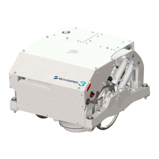
- Page 13 Product: Document #: Rev: Page: INSTALLATION MANUAL SEAKEEPER 3 90378 SEAKEEPER 3, Rear Oblique View SEAKEEPER 3, Front Oblique View 12VDC Power Input SW Pump DC Power Cable Terminator, Cable Female Adapter Touch Screen Display 10m Cable 2ft Cable FIGURE 1 – ELECTRICAL EQUIPMENT FOR...
- Page 14 Rev: Page: INSTALLATION MANUAL SEAKEEPER 3 90378 ( S e a k e e p e r r e c o m m e n d s A G M b a t t e r i e s )
- Page 15 Product: Document #: Rev: Page: INSTALLATION MANUAL SEAKEEPER 3 90378 a. Use heavy-duty eyelet (closed end) terminal such as Molex 19221-0235. Strip insulation from 2AWG conductor to the length of the terminal barrel approximately as shown. b. Insert stripped end of 2 AWG conductor fully into barrel of heavy-duty eyelet (closed end) terminal, approximately as shown.
- Page 16 Product: Document #: Rev: Page: INSTALLATION MANUAL SEAKEEPER 3 90378...
- Page 17 Product: Document #: Rev: Page: INSTALLATION MANUAL SEAKEEPER 3 90378 9 0 3 7 7...
- Page 18 Product: Document #: Rev: Page: INSTALLATION MANUAL SEAKEEPER 3 90378...
- Page 19 Product: Document #: Rev: Page: INSTALLATION MANUAL SEAKEEPER 3 90378 9 0 3 7 7...
- Page 20 Product: Document #: Rev: Page: INSTALLATION MANUAL SEAKEEPER 3 90378...
- Page 21 Product: Document #: Rev: Page: INSTALLATION MANUAL SEAKEEPER 3 90378 GROUND STUD...
- Page 22 FIGURE 12 – SERIAL COMMUNICATIONS LINK FOR OPERATOR STATION 2. ROUTE CAN COMMUNICATIONS CABLE a. The CAN Cable Assembly (30295, CABLE 3) is a 10 meter shielded cable and the largest connector is a molded plug with maximum outer diameter of .58 inch (14.8mm).
- Page 23 Product: Document #: Rev: Page: INSTALLATION MANUAL SEAKEEPER 3 90378 Display Installation Template The following template is for mounting; before using this template, measure to ensure that the shown size is actual. DISPLAY MOUNTING TEMPLATE...
- Page 24 Page: INSTALLATION MANUAL SEAKEEPER 3 90378 R e f e r e n c e D o c u m e n t s & D r a w i n g s : S e a F l o S e a w a t e r P u m p A s s e m b l y...
- Page 25 3. The seawater pump operates on 12 VDC with a max overcurrent protection rating of 15 A. 4. The seawater pump is powered by Cable 5, via “SW Pump 12 VDC Out” on the Seakeeper 3, as outlined in Electrical Installation Section.
- Page 26 Product: Document #: Rev: Page: INSTALLATION MANUAL SEAKEEPER 3 90378...
- Page 27 Product: Document #: Rev: Page: INSTALLATION MANUAL SEAKEEPER 3 90378...
- Page 28 Product: Document #: Rev: Page: INSTALLATION MANUAL SEAKEEPER 3 90378...
- Page 29 Product: Document #: Rev: Page: INSTALLATION MANUAL SEAKEEPER 3 90378...
- Page 30 Product: Document #: Rev: Page: INSTALLATION MANUAL SEAKEEPER 3 90378...
- Page 31 Seawater Strainer *included with Seakeeper Seawater Pump (P/N 30331) Seacock Valve 3/4 in. (19 mm) ID Seawater Suction Hose AND Discharge Hose Hose clamps for seawater plumbing to ¾ in. (19 mm) hose barb (2 per hose barb)
- Page 32 Product: Document #: Rev: Page: INSTALLATION MANUAL SEAKEEPER 3 90378...
- Page 33 @ s e a k e e p e r . c o m o r t e l e f a x t o + 1 . 4 1 0 . 3 2 6 . 1 1 9 9 Connect Cable 5 from mating connector on Seakeeper wire harness to customer-...
- Page 34 (The seawater pump output will operate for two minutes after the Seakeeper is turned on. During operation, the seawater pump output is turned on and o based on the temperature of the Seakeeper)
- Page 35 SEAKEEPER 3 90378 DC power and seawater pump may be turned o after the Seakeeper is turned o by placing the Seakeeper in LOCK mode and turning the Seakeeper o Seakeeper 3 takes 8+ hours to coast down to 0 RPM from full speed...
- Page 36 Clearances around Seakeeper meet service and operating speci cations and no obstructions are within the Seakeeper envelope. Seakeeper 3 Bolt-In Kit (P/N 90375) or Through-bolt Kit (P/N 90641) is installed with a minimum thread engagement of 0.8″ (20.42 mm) or bolt passing entirely through backing nut.
- Page 37 Product: Document #: Rev: Page: INSTALLATION MANUAL SEAKEEPER 3 90378...
- Page 38 Product: Document #: Rev: Page: INSTALLATION MANUAL SEAKEEPER 3 90378...
- Page 39 15A breaker, and seawater pump breaker. Verify Seakeeper display is active and no alarms present. * If the Seakeeper 3 display does not activate, turn o all circuit breakers immediately and check all wiring connections. Check that battery voltage exceeds 12 VDC. A minimum battery voltage of 11.2 VDC is required for the duration of Seakeeper spool-up.
Need help?
Do you have a question about the 3 and is the answer not in the manual?
Questions and answers