Advertisement
Quick Links
Advertisement

Related Manuals for Seakeeper 26 GYRO


Summary of Contents for Seakeeper 26 GYRO
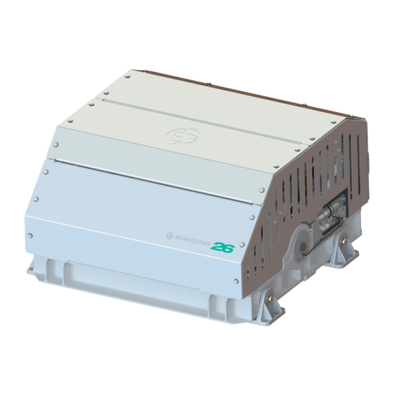
- Page 1 INSTALLATION MANUAL SEAKEEPER 26 GYRO Rev 2 FEBRUARY 2015...
- Page 2 PAGE INTENTIONALLY LEFT BLANK...
-
Page 3: Installation
Product: Document #: Rev: INSTALLATION MANUAL SEAKEEPER 26 GYRO 90265 SEAKEEPER 26 GYRO INSTALLATION MANUAL FEBRUARY 2015 Contents: Section 1 – Mechanical Installation & PC-120 Guide Section 2 – Electrical Installation Section 3 – Cooling Installation Section 4 – Startup Section 5 –... - Page 4 PAGE INTENTIONALLY LEFT BLANK...
-
Page 5: Reference Drawings
This document is intended to give details and guidance to a boat builder or equipment installer to install the Seakeeper 26 Stabilizing Gyro. The gyro is capable of producing loads up to 35.89 KN (8,070 lbs.) at each of the four mounts and careful consideration should be given to foundation design to insure it is capable of transferring these loads into the hull. - Page 6 Product: Document #: Rev: Page: INSTALLATION MANUAL 2 of 22 SEAKEEPER 26 GYRO 90265 Section 1: MECHANICAL INSTALLATION Precautions • Gyro must only be lifted from the supplied lifting eyes (See Section 1.4). • Gyro flywheel is supported by precision bearings. Make certain while unpacking and lifting gyro assembly to NOT drop or impart mechanical shock as damage to bearings could result.
- Page 7 Rev: Page: INSTALLATION MANUAL 3 of 22 SEAKEEPER 26 GYRO 90265 Section 1: MECHANICAL INSTALLATION VIEWS SHOWING RECOMMENDED CLEARANCES AROUND GYRO FOR USE OF HAND TOOLS, EASE OF MAINTENANCE, INSTALLATION AND PROPER OPERATION. FIGURE 2 – INSTALLED GYRO CLEARANCE CONSIDERATIONS...
- Page 8 Noise/Soundproofing Gyro noise has been measured under steady state conditions (no wave load) in Seakeeper's lab and in our test boat. The steady state noise is typically in the range of 70-75 dB un-weighted. As the...
- Page 9 Section 1: MECHANICAL INSTALLATION Selection of Installation Method The Seakeeper 26 gyro can be affixed to the hull structure using two methods 1) Use bolt-in installation or 2) saddle installation. See figures below. OPTION 1- DIRECT FASTENING OF GYRO FOUNDATION TO SHIPS STRUCTURE Option 1 would be applied when a metal structure is available for attachment.
-
Page 10: Unpacking Crate
90265 Section 1: MECHANICAL INSTALLATION Unpacking Crate 1) Reference Seakeeper Drawing No. 90244 Seakeeper 26 Gyro Hardware Scope of Supply for items that ship with the gyro. 2) Remove electrical components, cables, and misc. items and set aside. 3) Remove packing materials that secure gyro assembly inside the crate. - Page 11 (Similar to Figure 9). Seakeeper provides an installation fixture assembly, P/N 90089, that contains four plates that mimic the mating surfaces of the four isolation mounts located on the gyro’s foundation. These plates have 8 holes located at the same centers as the holes in the isolation mounts.
- Page 12 Product: Document #: Rev: Page: INSTALLATION MANUAL 8 of 22 SEAKEEPER 26 GYRO 90265 Section 1: MECHANICAL INSTALLATION FIGURE 6 – NOTICE FOR CHECKING SQUARE OF ASSEMBLY...
- Page 13 Product: Document #: Rev: Page: INSTALLATION MANUAL 9 of 22 SEAKEEPER 26 GYRO 90265 Section 1: MECHANICAL INSTALLATION 1.5.2 Transfer of Holes to Foundation 1) Lower assembled fixture onto gyro foundation. The four areas where the isolation mounts will rest should be coplanar to within 1/8”...
- Page 14 Document #: Rev: Page: INSTALLATION MANUAL 10 of 22 SEAKEEPER 26 GYRO 90265 Section 1: MECHANICAL INSTALLATION 1.5.3 Installation of Gyro 1) Locate and position 4 isolation gaskets onto foundation beams. NOTE: Sealant or caulk is NOT recommended to be applied.
- Page 15 Section 1: MECHANICAL INSTALLATION 1.6 Saddle Installation Seakeeper has used Plexus MA590 adhesive for bonding the saddles to the GRP hull structure. Plexus MA590 is a two-part methacrylate structural adhesive that has characteristics conducive to this type of installation. Details of the bonding procedure in this manual will involve the Plexus MA590 product but that should not exclude other suitable adhesives the installer chooses to use.
- Page 16 Note: Do NOT use the installation fixture to establish gyro envelope dimensions. Refer to Drawing No. 90272 for envelope dimensions. A 3-D model of the gyro is available on the Seakeeper website (www.seakeeper.com) to aid in designing the gyro foundation and the space around the gyro.
- Page 17 Product: Document #: Rev: Page: INSTALLATION MANUAL 13 of 22 SEAKEEPER 26 GYRO 90265 Section 1: MECHANICAL INSTALLATION FIGURE 7 – NOTICE FOR CHECKING SQUARE OF ASSEMBLY...
- Page 18 Product: Document #: Rev: Page: INSTALLATION MANUAL 14 of 22 SEAKEEPER 26 GYRO 90265 Section 1: MECHANICAL INSTALLATION FIGURE 8 – SADDLE INSTALLATION FIXTURE ON NOTIONAL HULL STRUCTURE...
- Page 19 Rev: Page: INSTALLATION MANUAL 15 of 22 SEAKEEPER 26 GYRO 90265 Section 1: MECHANICAL INSTALLATION 1.6.2 Fiberglass Hull Preparation 1) Position installation fixture (Fig 9) on hull girders noting recommended clearances for maintenance from Figure 2. Check that the screws fastening the saddles to the installation fixture are tight (Fig 6).
- Page 20 8) Re-position installation fixture on girders and double-check that the adhesive gap is within the adhesive manufacturer’s maximum recommended thickness. (Note gap will be larger due to absence of gel-coat.) Seakeeper recommends a maximum gap of 3mm if using Plexus MA590.
- Page 21 These strips are to serve as a minimize adhesive escaping out the ends of the saddles as they are positioned over the bond area. FIGURE 12 – FOAM STRIP INSTALLATION Note if bonding saddles to a non-composite hull, contact Seakeeper for hull preparation instructions.
- Page 22 Rev: Page: INSTALLATION MANUAL 18 of 22 SEAKEEPER 26 GYRO 90265 Section 1: MECHANICAL INSTALLATION 1.6.3 Gyro Saddle Preparation 1) Ensure that screws fastening saddles to the installation fixture are tight (Fig 7). 2) Check that each saddle contains 4 plastic screws which will insure an adhesive gap of .080” (2 mm) on top surface of hull as shown in Figure 13.
- Page 23 Document #: Rev: Page: INSTALLATION MANUAL 19 of 22 SEAKEEPER 26 GYRO 90265 Section 1: MECHANICAL INSTALLATION 1.6.4 Bonding Saddles to Hull Note: If using Plexus MA590 adhesive, the gyro saddles should be installed when PC-120 is confirmed dry. 1) Assemble Plexus cartridge into either the manual or pneumatic gun as shown. Remove cap on cartridge and attach mixing tip.
- Page 24 Product: Document #: Rev: Page: INSTALLATION MANUAL 20 of 22 SEAKEEPER 26 GYRO 90265 Section 1: MECHANICAL INSTALLATION 5) Apply large bead of Plexus adhesive to the hull structure as shown in the figure right. Apply approximately 1 ½ cartridges at each of the four locations.
- Page 25 2) Adjust position of gyro until alignment is achieved for the 32 fasteners that will attach gyro foundation frame to saddles. 3) Install Seakeeper supplied M16 fasteners as shown in figure to right– apply a moderate coat of nickel based anti-seize...
- Page 26 Product: Document #: Rev: Page: INSTALLATION MANUAL 22 of 22 SEAKEEPER 26 GYRO 90265 Section 1: MECHANICAL INSTALLATION 1.7 Doc # 90213 Plexus PC-120 Application Instructions...
- Page 27 INSTRUCTIONS Product: All Document #: 90213 Process: Plexus PC- 120 Application Instructions Rev.: 1 Process Description: Instructions for use of surface conditioner Page 1 of 4 What is Plexus PC-120? • Plexus PC-120 is a dual function primer/conditioner designed to clean surface contamination and leave a thin coating of primer on specific metal surfaces.
- Page 28 INSTRUCTIONS Page 2 of 4 Product: ALL Document #: 90213 Process: Plexus PC- 120 Application Instructions Rev.: 1 1) Using too much PC-120 • Only a very thin coat should be left on the metal. You should be able to see a slight “pink” cast as illustrated below.
- Page 29 INSTRUCTIONS Page 3 of 4 Product: ALL Document #: 90213 Process: Plexus PC- 120 Application Instructions Rev.: 1 3) Not abrading corroded surfaces • As good as PC-120 is, it can’t help bonding performance if applied to a surface that is already corroded! •...
- Page 30 INSTRUCTIONS Page 4 of 4 Product: ALL Document #: 90213 Process: Plexus PC- 120 Application Instructions Rev.: 1 Remember these points! To avoid problems with Plexus PC-120: • Don’t use too much PC-120. Only a thin layer is needed. • Use a clean rag to wipe PC-120 off before it completely dries to remove surface contaminants it has cleaned.
-
Page 31: Section 2: Electrical Installation
90267 Seakeeper 26 Gyro Drawing Manual SEAKEEPER 26 Gyro, Front Oblique View SEAKEEPER 26 Gyro, Rear Oblique View 24VDC Power Connector Terminator, Female Tee Adapter 20223 Color Display Display Interface Cable 25m Cable FIGURE 1 – ELECTRICAL EQUIPMENT FOR SEAKEEPER 26 GYRO... - Page 32 Precautions • Each item of electrical equipment has specific mounting instructions. These instructions should be followed to insure proper function of the SEAKEEPER 26 Gyro. Do NOT move Gyro mounted components from their locations or incorrect Gyro operation will result.
- Page 33 2. DRIVE BOX AC POWER INPUT CONNECTION INSTRUCTIONS a. Cable: 3 x 10AWG (3 x 6mm CSA), 10’ (3m) length, Seakeeper supplied pre-installed. i. Locate CABLE 2 for AC power input to the Drive Box at the outward of three cable glands.
- Page 34 Figure 3 above. 3. DRIVE BOX AC POWER OUTPUT TO SEAWATER PUMP CONNECTION INSTRUCTIONS a. Cable: 3 x 14AWG (3 x 2.0mm CSA) cable, 10’ (3m) length, Seakeeper supplied pre- installed. b. Pumps rated at 230 VAC, 5 Amps max., Customer-supplied.
- Page 35 Product: Document #: Rev: Page: INSTALLATION MANUAL SEAKEEPER 26 GYRO 90265 5 of 12 Section 2: ELECTRICAL INSTALLATION CABLE 5 DRIVE BOX 3x14AWG or 3x2.0mm SEAKEEPER SUPPLIED, 3m LENGTH SEA WATER SEAWATER PUMP BLACK PUMP, POWER OUTPUT, CUSTOMER 208-230 VAC,...
- Page 36 24 VDC, 10 Amps. 2 x 12AWG (3 x 4mm CSA) customer supplied. i. Install Seakeeper provided DC Power Input Cable, P/N: 20248 as CABLE 1. 1. Route CABLE 1 to DC Power Distribution Panel. 2. Terminate RED conductor to +24 VDC. Terminate BLACK conductor to 24V Rtn or Zero VDC.
- Page 37 Product: Document #: Rev: Page: INSTALLATION MANUAL SEAKEEPER 26 GYRO 90265 7 of 12 Section 2: ELECTRICAL INSTALLATION Electrical Equipment Ground Connections 1. GYRO TO VESSEL GROUND CONNECTION INSTRUCTIONS a. Connect the Gyro foundation to vessel ground. i. Install CABLE 6 (4AWG or 22.0mm , Customer supplied) from the M6 brass ground stud on the Gyro rear brace to a suitable vessel ground.
- Page 38 This section explains the connection between the Operator Station equipment and the Gyro Control Box. Reference Drawing 90310 Seakeeper 26 Gyro Cable Block Diagram 1. DETERMINE LOCATION OF OPERATOR STATION a. The desired location of the Operator Station must be determined with respect to the vessel arrangement.
- Page 39 Product: Document #: Rev: Page: INSTALLATION MANUAL SEAKEEPER 26 GYRO 90265 9 of 12 Section 2: ELECTRICAL INSTALLATION 3. INSTALL OPERATOR STATION EQUIPMENT a. The Operator Station equipment is installed at the selected location using Electrical Equipment Mounting Instructions in Section 2.1.
- Page 40 Operator Station Kit. Reference Drawings 90250 Seakeeper 26 Gyro 2 Operator Station Kit 90310 Seakeeper 26 Gyro Cable Block Diagram (includes detail of 2nd Operator Station) 1. DETERMINE LOCATION OF 2 OPERATOR STATION a. The desired location of the 2 Operator Station must be determined with respect to the Operator Station and the vessel arrangement.
- Page 41 Product: Document #: Rev: Page: INSTALLATION MANUAL SEAKEEPER 26 GYRO 90265 11 of 12 Section 2: ELECTRICAL INSTALLATION 3. ROUTE 2 OPERATOR STATION CABLE a. A second CAN Cable Assembly (30243), also a 25 meter shielded cable, and the largest connector is a molded plug with maximum outer diameter of .58 inch (14.8mm)).
- Page 42 PAGE INTENTIONALLY LEFT BLANK...
- Page 43 Product: Document #: Rev: Page: INSTALLATION MANUAL SEAKEEPER 26 GYRO 90265 12 of 12 Section 2: ELECTRICAL INSTALLATION Display Installation Template The following template is for mounting; before using this template, measure to ensure that the shown size is actual.
- Page 44 PAGE INTENTIONALLY LEFT BLANK...
- Page 45 1 of 5 Section 3: COOLING INSTALLATION Introduction The Seakeeper 26 is shipped with the cooling circuit filled and ready for use. Only a quick confirmation of glycol level is required. Reference Drawings 90244 Seakeeper 26 Gyro Hardware Scope of Supply...
- Page 46 Product: Document #: Rev: Page: INSTALLATION MANUAL SEAKEEPER 26 GYRO 90265 2 of 5 Section 3: COOLING INSTALLATION FIGURE 2 – SEAKEEPER 26 GYRO COOLING COMPONENTS...
-
Page 47: Adding Coolant
If level has dropped, check for evidence of leaks at all connections before adding fluid as described below. If coolant is at the correct level, skip to sea water connection in section 3.3. FIGURE 3 – SEAKEEPER 26 COOLANT LEVEL... - Page 48 Document #: Rev: Page: INSTALLATION MANUAL SEAKEEPER 26 GYRO 90265 4 of 5 Section 3: COOLING INSTALLATION Mix 50% ethylene glycol with 50% distilled water in a clean container. Refer to Table 1 or glycol manufacturer’s literature for freezing points.
- Page 49 Inspect raw water plumbing after sea trial for any signs of leakage. Heat exchanger contains removable end-caps to provide access for cleaning the tube bundle. FIGURE 4 – SEAKEEPER 26 SEAWATER CONNECTIONS...
- Page 50 PAGE INTENTIONALLY LEFT BLANK...
-
Page 51: Section 4: Startup
Section 4: STARTUP Introduction This section describes the first startup of the gyro. Also reference Seakeeper Document # 90266, Seakeeper 26 Gyro Operation Manual. • Previous sections for mechanical, electrical and cooling installation must be completed before this startup sequence is initiated. - Page 52 Product: Document #: Rev: Page: INSTALLATION MANUAL SEAKEEPER 26 GYRO 90265 2 of 3 Section 4: STARTUP 5) Press the GYRO ON/OFF Button on Display. The RED LOCK ICON and the PROGRESS BAR will appear and be RED until the GYRO is at speed, then stabilization can begin.
- Page 53 Document #: Rev: Page: INSTALLATION MANUAL SEAKEEPER 26 GYRO 90265 3 of 3 Section 4: STARTUP 11) During normal operation, the gyro should be stopped when pulling into port and stabilization is no longer required. This maximizes long term life as it allows the gyro to start the coast down cycle before cooling is shutoff.
- Page 54 PAGE INTENTIONALLY LEFT BLANK...
- Page 55 Mechanical Checklist (reference Installation Manual Section 1) Gyro Foundation Installed in Hull Foundation bolts torqued to specification Electrical Checklist (reference Seakeeper Drawing 90310 & Installation Manual Section 2) Mount Components Display (near helm) Connect Customer Supplied Cables ...
- Page 56 Connect male end of CAN communications Cable 3 at helm to CAN Tee Adapter – Connect Display and Seakeeper supplied Cable 4 to CAN Tee Adapter with CAN Terminator Cooling Checklist (reference Installation Manual Section 3) Verify coolant level in heat exchanger coolant reservoir.
-
Page 57: Item Description
Product: Document #: Rev: Page: INSTALLATION MANUAL SEAKEEPER 26 GYRO 90265 3 of 4 Section 5: INSTALLATION CHECKLIST AND SUPPLIES Required Supplies needed for Gyro Installation (not supplied with gyro) Installation Manual Other Item Description System Reference Reference Section Adhesive and cleaning supplies for bonding to hull... - Page 58 Product: Document #: Rev: Page: INSTALLATION MANUAL SEAKEEPER 26 GYRO 90265 4 of 4 Section 5: INSTALLATION CHECKLIST AND SUPPLIES List of common tools that may be required for installation Item Description Wire cutter DC Power, AC Power cables Wire stripper...
Need help?
Do you have a question about the 26 GYRO and is the answer not in the manual?
Questions and answers