Advertisement
Quick Links
Advertisement

Related Manuals for Seakeeper 26


Summary of Contents for Seakeeper 26
- Page 1 INSTALLATION MANUAL *THIS MANUAL ALSO COVERS THE SEAKEEPER 20HD* Rev 7 MAR 2021...
- Page 2 Product: Document #: Rev: INSTALLATION MANUAL SEAKEEPER 26 / 20HD 90265 SEAKEEPER 26 / 20HD INSTALLATION MANUAL MARCH 2021 Contents: Section 1 – Mechanical Installation & PC-120 Guide Section 2 – Electrical Installation Section 3 – Cooling Installation Section 4 – Installation Supplies & Tools Section 5 –...
-
Page 3: Reference Drawings
This document is intended to give details and guidance to a boat builder or equipment installer to install the Seakeeper 26. The Seakeeper can produce loads up to 35.89 KN (8,070 lbs.) at each of the four mounts and careful consideration should be given to foundation design to ensure it can transfer these loads into the hull. - Page 4 2 of 21 Section 1: MECHANICAL INSTALLATION Precautions • The Seakeeper must only be lifted from the supplied lifting eyes (See Section 1.4). • The Seakeeper flywheel is supported by precision bearings. Make certain while unpacking and lifting the Seakeeper assembly to NOT drop or impart mechanical shock as damage to bearings could result.
- Page 5 INSTALLATION MANUAL SEAKEEPER 26 / 20HD 90265 3 of 21 Section 1: MECHANICAL INSTALLATION VIEWS SHOWING RECOMMENDED CLEARANCES AROUND THE SEAKEEPER FOR USE OF HAND TOOLS, EASE OF MAINTENANCE, INSTALLATION, AND PROPER OPERATION FIGURE 2 – INSTALLED SEAKEEPER CLEARANCE CONSIDERATIONS...
- Page 6 Seakeeper noise has been measured under steady state conditions (no wave load) in Seakeeper's lab. The steady state noise is typically in the range of 70-75 dB un-weighted. As the frequencies emitting the highest sound pressures are low (like other marine machinery), it is recommended that the Seakeeper be installed in a machinery space that is already treated with soundproofing.
- Page 7 5 of 21 Section 1: MECHANICAL INSTALLATION Selection of Installation Method The Seakeeper 26 can be affixed to the hull structure using two methods shown below: 1) Bolt-In Installation 2) Bond-In (Saddle) Installation OPTION 1 - DIRECT FASTENING OF SEAKEEPER FOUNDATION TO SHIPS STRUCTURE Option 1 would be applied when a metal structure is available for attachment.
-
Page 8: Unpacking Crate
4) Remove top and angled face cover panels to access lifting eyes. 5) Attach spreader bar to the two lifting eyes located on the top of the Seakeeper enclosure. Stay clear of any other parts on the Seakeeper. See Figure 3 below. - Page 9 Method. Important dimensional and load information is given in this drawing that will impact the design details of the structure that will receive the Seakeeper. It is assumed that a proper structural analysis has been performed for the hull structure to which the Seakeeper will be fastened to ensure proper strength margins for the loads the Seakeeper will create during operation.
- Page 10 Product: Document #: Rev: Page: INSTALLATION MANUAL SEAKEEPER 26 / 20HD 90265 8 of 21 Section 1: MECHANICAL INSTALLATION FIGURE 6 – NOTICE FOR CHECKING SQUARE OF ASSEMBLY...
- Page 11 Product: Document #: Rev: Page: INSTALLATION MANUAL SEAKEEPER 26 / 20HD 90265 9 of 21 Section 1: MECHANICAL INSTALLATION 1.5.2 Transfer of Holes to Foundation 1) Lower assembled fixture onto hull structure. The four areas where the isolation mounts will rest should be coplanar to within 1/8”...
- Page 12 GRP. 2) Lower Seakeeper into position onto foundation beams and align over drilled holes. 3) Install Seakeeper supplied M16 fasteners as shown in figure to right– apply a moderate coat of nickel based anti-seize compound to the threads of each bolt prior to installation.
- Page 13 Refer to Seakeeper Drawing No. 90272, Seakeeper 26/20HD Saddle Installation Details. Important dimensional and load information is given in this drawing that will impact the design details of the structure that will receive the Seakeeper as well as selection of the adhesive to bond the Seakeeper into the hull.
- Page 14 90265 12 of 21 Section 1: MECHANICAL INSTALLATION Note: Do NOT use the installation fixture to establish Seakeeper envelope dimensions. Refer to Drawing No. 90272 for envelope dimensions. A 3-D model of the Seakeeper is available on the Seakeeper website (www.seakeeper.com) to aid in designing the Seakeeper foundation and the space around the Seakeeper.
- Page 15 Product: Document #: Rev: Page: INSTALLATION MANUAL SEAKEEPER 26 / 20HD 90265 13 of 21 Section 1: MECHANICAL INSTALLATION FIGURE 7 – NOTICE FOR CHECKING SQUARE OF ASSEMBLY...
- Page 16 Product: Document #: Rev: Page: INSTALLATION MANUAL SEAKEEPER 26 / 20HD 90265 14 of 21 Section 1: MECHANICAL INSTALLATION FIGURE 8 – SADDLE INSTALLATION FIXTURE ON NOTIONAL HULL STRUCTURE...
- Page 17 Product: Document #: Rev: Page: INSTALLATION MANUAL SEAKEEPER 26 / 20HD 90265 15 of 21 Section 1: MECHANICAL INSTALLATION 1.6.2 Fiberglass Hull Preparation 1) Position installation fixture (Fig 9) on hull girders noting recommended clearances for maintenance from Figure 2. Check that the screws fastening the saddles to the installation fixture are tight (Fig 6).
- Page 18 8) Re-position installation fixture on girders and double-check that the adhesive gap is within the adhesive manufacturer’s maximum recommended thickness. (Note gap will be larger due to absence of gel-coat.) Seakeeper recommends a maximum gap of 3 mm if using Plexus MA590.
- Page 19 FIGURE 12 – FOAM STRIP INSTALLATION Note if bonding saddles to a non-composite hull, contact Seakeeper for hull preparation instructions.
- Page 20 .080” (2 mm) on top surface of hull as shown in Figure 13. 3) Thoroughly clean with alcohol or acetone the inside surfaces of Seakeeper foundation saddles to remove any contaminates as shown in Figure 13. Use new paper towels for cleaning, not shop rags.
- Page 21 Section 1: MECHANICAL INSTALLATION 1.6.4 Bonding Saddles to Hull Note: If using Plexus MA590 adhesive, the Seakeeper saddles should be installed when PC- 120 is confirmed dry. 1) Assemble Plexus cartridge into either the manual or pneumatic gun as shown. Remove cap on cartridge and attach mixing tip.
- Page 22 Product: Document #: Rev: Page: INSTALLATION MANUAL SEAKEEPER 26 / 20HD 90265 20 of 21 Section 1: MECHANICAL INSTALLATION 5) Apply large bead of Plexus adhesive to the hull structure as shown in the figure to the right. Apply approximately 1 ½...
- Page 23 Allow adhesive to cure per manufacturer’s recommendations. Follow adhesive guidelines for curing time versus temperature. 12) Bonding of Seakeeper saddles onto the hull is now complete. Remove installation fixture. 1.6.5 Installation of Seakeeper 1) Rig the Seakeeper for lifting and lower it into position onto top surface of four saddles.
- Page 24 INSTRUCTIONS Product: All Document #: 90213 Process: Plexus PC‐ 120 Application Instructions Rev.: 2 Process Description: Instructions for use of surface conditioner Page 1 of 4 What is Plexus PC‐120? Plexus PC‐120 is a dual function primer/conditioner designed to clean surface contamination and leave a thin coating of primer on specific metal surfaces. Although designed specifically for cleaning and priming of Aluminum and Stainless Steel, PC‐120 can be used to clean other surfaces in special situations. Contact Plexus Technical Service for recommendations on any surface other than Aluminum or Stainless Steel. Plexus PC‐120 works by: Cleaning the surface of contamination using Isopropyl Alcohol to “lift” machine oils and other contamination. Depositing a thin Phosphate based coating to retard corrosion. Leaving a light “pink” color to assist in determining what areas have, and have not, been treated with PC‐120. How should PC‐120 be used? PC‐120 can be brushed, wiped or sprayed onto the surface being primed. ...
- Page 25 INSTRUCTIONS Page 2 of 4 Product: ALL Document #: 90213 Process: Plexus PC‐ 120 Application Instructions Rev.: 2 1) Using too much PC‐120 Only a very thin coat should be left on the metal. You should be able to see a slight “pink” cast as illustrated below. Too Much PC‐120 Correct Amount 2) Not removing oils once primed Wipe the surface with a dry rag The solvents in PC‐120 will clean and “lift” most machining oils, but if the metal isn’t wiped clean of these oils then they will be deposited right back onto the metal surface when the solvent in PC‐120 evaporates! ...
- Page 26 INSTRUCTIONS Page 3 of 4 Product: ALL Document #: 90213 Process: Plexus PC‐ 120 Application Instructions Rev.: 2 3) Not abrading corroded surfaces As good as PC‐120 is, it can’t help bonding performance if applied to a surface that is already corroded! Any surface that shows signs of corrosion should be cleaned by sanding or wire brushing to remove any scale or corrosion. After removal of corrosion then treat the surface with PC‐120 as you normally would. 4) Using PC‐120 past it’s shelf life When stored under normal conditions PC‐120 has a shelf life of 12 months in an unopened, original container. PC‐120 bottles are marked with a lot number that is a simple 8 digit code that gives you the date of manufacture. o “807241” for example is 2008, 07 month (July), 24th day (the “1” refers to the first batch of PC‐120 made that day). Use the lot number to make sure the material is still within shelf life. Since it contains isopropyl alcohol, PC‐120 should be tightly capped when not in use to stop evaporation. ...
- Page 27 INSTRUCTIONS Page 4 of 4 Product: ALL Document #: 90213 Process: Plexus PC‐ 120 Application Instructions Rev.: 2 Remember these points! To avoid problems with Plexus PC‐120: Don’t use too much PC‐120. Only a thin layer is needed. Use a clean rag to wipe PC‐120 off before it completely dries to remove surface contaminants it has cleaned. Good quality paper towels are a better choice to minimize introduction of contaminates to surface. Any sign of corrosion already on the surface should be removed by abrading BEFORE priming. Check the lot number for the date to make sure the PC‐120 is less than a year old. Questions Please contact Plexus Technical Service at 1‐800‐851‐6692 or info@itwplexus.com ...
-
Page 28: Section 2: Electrical Installation
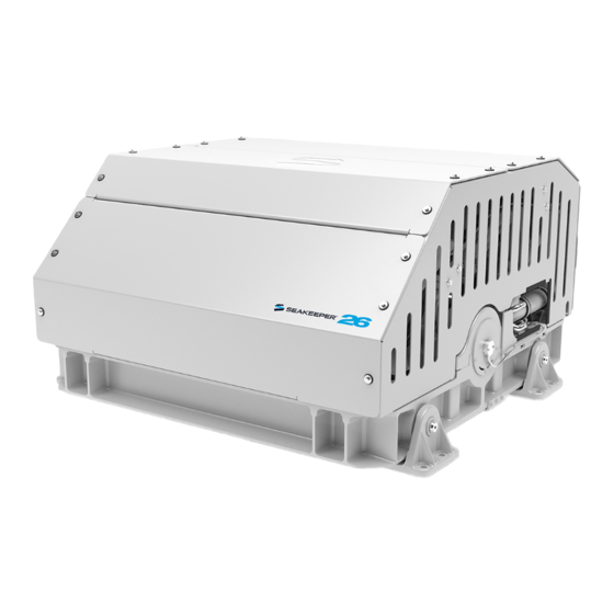
90438 Touchscreen Display Envelope and Mounting Details SEAKEEPER 26, Front Oblique View SEAKEEPER 26, Rear Oblique View 24VDC Power Connector Terminator, Female Tee Adapter Color Display USB Extension Cable 2ft Cable 25m Cable FIGURE 1 – ELECTRICAL EQUIPMENT FOR SEAKEEPER 26... - Page 29 TB 90480, SIMRAD AND SEAKEEPER COMPATIBILITY iv. Additional MFD Compatibility will be added as new integrations become available. Please contact Seakeeper for additional information. b. Seakeeper MFD Compatibility cable part numbers can be found in the relevant technical bulletin for the specific MFD, listed above.
- Page 30 1. 230 VAC POWER SOURCE REQUIREMENTS a. 230 VAC (nominal), 1 Phase, 50/60 Hz, 20 Amps. b. A separate circuit breaker should be used for each Seakeeper Motor Drive Box. 2. DRIVE BOX AC POWER INPUT CONNECTION INSTRUCTIONS CSA), 10’ (3m) length, Seakeeper supplied pre- a.
- Page 31 Section 2: ELECTRICAL INSTALLATION 3. DRIVE BOX AC POWER OUTPUT TO SEAWATER PUMP CONNECTION INSTRUCTIONS CSA) cable, 10’ (3m) length, Seakeeper supplied a. Cable: 3 x 14AWG (3 x 2.0mm pre-installed. b. Pumps rated at 230 VAC, 5 Amps max., Customer-supplied.
- Page 32 Seakeeper operation. Do NOT cut CABLE 5 as it contains live voltage when Seakeeper is in operation. Seakeeper ships with CABLE 5 permanently sealed at end of cable with protective cap in the event it is not used.
- Page 33 24 VDC, 10 Amps. 2 x 12AWG (3 x 4mm CSA) customer supplied. i. Install Seakeeper provided DC Power Input Cable, P/N: 20248 as CABLE 1. 1. Route CABLE 1 to DC Power Distribution Panel. 2. Terminate RED conductor to +24 VDC. Terminate BLACK conductor to 24V Rtn or Zero VDC.
- Page 34 1. SEAKEEPER TO VESSEL GROUND CONNECTION INSTRUCTIONS a. Connect the Seakeeper foundation to vessel ground. i. Install CABLE 6 (10AWG or 6.0 mm , Customer supplied) from the M6 brass ground stud at the rear of the Seakeeper frame to a suitable vessel ground. GROUND STUD...
-
Page 35: Operator Station
The operator display should be located on the bridge console. c. Figure 9 below shows the CANbus communications link for the Operator Station. The Terminator goes on the far end of the Tee Adapter from the Seakeeper. FIGURE 9 – SERIAL COMMUNICATIONS LINK FOR OPERATOR STATION... - Page 36 .58 inch (14.8mm). b. CABLE 3 must be routed and installed in the vessel from the Seakeeper (female end) to the Tee Adapter (male end) at the Operator Station.
- Page 37 Stations. The Terminator must be installed on the Tee Adapter farthest from the Seakeeper. FIGURE 11 – CABLING FOR 2 OPERATOR STATIONS b. The Operator Station nearest the Seakeeper should be connected to CABLE 3. 3. ROUTE 2 OPERATOR STATION CABLE a.
- Page 38 TB 90479, Raymarine and Seakeeper Compatibility TB 90480, Simrad and Seakeeper Compatibility 1. The Seakeeper can be connected to a variety of available MFD systems. Refer to the Technical Bulletins Section of the Seakeeper Technical Library for manufacturer specific MFD compatibility technical bulletins.
- Page 39 Product: Document #: Rev: Page: INSTALLATION MANUAL SEAKEEPER 26 / 20HD 90265 12 of 13 Section 2: ELECTRICAL INSTALLATION FIGURE 13 – ETHERNET PORT ON OPERATOR STATION...
- Page 40 Product: Document #: Rev: Page: INSTALLATION MANUAL SEAKEEPER 26 / 20HD 90265 13 of 13 Section 2: ELECTRICAL INSTALLATION Display Installation Template The following template is for mounting. Before using this template, measure to ensure that the shown size is actual.
- Page 41 1 of 4 Section 3: COOLING INSTALLATION Introduction The Seakeeper 26 is shipped with the cooling circuit filled and ready for use. Only a quick confirmation of glycol level is required. Reference Drawings 90244 Seakeeper 26 Hardware Scope of Supply...
-
Page 42: Adding Coolant
• Installer is responsible for supplying a dedicated seawater pump and associated plumbing. Seawater connections on the Seakeeper heat exchanger mate with ¾ inch (19 mm) hose. • There is no need to disconnect hose from glycol pump except to replace the pump. In this case, provision will need to be made to catch draining glycol as plumbing is disconnected. - Page 43 Document #: Rev: Page: INSTALLATION MANUAL SEAKEEPER 26 / 20HD 90265 3 of 4 Section 3: COOLING INSTALLATION Mix 50% ethylene glycol with 50% distilled water in a clean container. Refer to Table 1 or glycol manufacturer’s literature for freezing points.
- Page 44 Refer to Figure 1. In addition to initial operation at dock, new Seakeeper installations should be checked for minimum 4 GPM (16 LPM) flow while vessel is at speed and when backing down. If no other method of confirming flow is available, discharge line may be temporarily diverted to a bucket.
- Page 45 Introduction The Installation Requirements section outlines the components and tools needed for the Seakeeper installation that are not included within the scope of supply. Supplies required for installation The table below outlines the customer supplied components required for the installation.
-
Page 46: Tools Required For Installation
Product: Document #: Rev: Page: INSTALLATION MANUAL SEAKEEPER 26 / 20HD 90265 2 of 2 Section 4: INSTALLATION SUPPLIES & TOOLS Tools required for installation The table below outlines the typical tools and equipment required for the installation. Item Description... -
Page 47: Installation Checklist
The Installation and Start-Up Checklists in this section provide an overview of the primary steps covered in the installation manual and should be referenced throughout the installation process. Upon completing the installation, the installer should commission each Seakeeper unit with the Seakeeper Commissioning Form (90437). The Commissioning Checklist (SWI-105) provides a checklist of items to inspect and verify during the commissioning process and serves as a supplement to the Commissioning Form. - Page 48 10 AWG ground cable – ❑ Connect one end of Cable 6 to nearest vessel ground and other end to Seakeeper rear brace Connect Seakeeper Supplied Cables ❑ Cable 2 (Seakeeper supplied) – Connect Cable 2 from Drive Box to 230 VAC...
-
Page 49: Start-Up Checklist
Follow instructions in Section 2 of Operation Manual to turn off the Seakeeper. ❑ AC & DC power and sea water pump may be turned off after the Seakeeper is turned off by placing the Seakeeper in LOCK mode and Turning the Seakeeper off.
Need help?
Do you have a question about the 26 and is the answer not in the manual?
Questions and answers