Table of Contents
Advertisement
Quick Links
Machine Controller MP2300S
USER'S MANUAL
Model: JEPMC-MP2300S-E
MP2300S
YASKAWA
BATTERY
M-I/II
MANUAL NO. SIEP C880732 00C
RDY
RUN
ALM
ERR
MTX
BAT
TRX
IP
STOP
SUP
INT
SW
CNFG
1
MON
TEST
NO
ON
SW
E-INT
2
E-TEST
NO
ON
RLY
OUT
Ethernet
LINK
DC
24V
DC
0V
100M
System Start Up and
Easy Programming
Appendices
1
2
3
4
5
6
7
8
9
A
Advertisement
Table of Contents
Troubleshooting

Related Manuals for YASKAWA MP2300S


Summary of Contents for YASKAWA MP2300S
- Page 1 Machine Controller MP2300S Basic Module USER'S MANUAL Model: JEPMC-MP2300S-E MP2300S YASKAWA STOP CNFG TEST Overview Specifications and Functions E-INT E-TEST BATTERY M-I/II Mounting and Wiring System Start Up and Ethernet Easy Programming LINK Outline of Motion Control Systems 100M Built-in Ethernet Communications...
- Page 2 Yaskawa. No patent liability is assumed with respect to the use of the information contained herein. Moreover, because Yaskawa is constantly striving to improve its high-quality products, the information contained in this manual is subject to change without notice.
- Page 3 The MP2300S is a compact Machine Controller that contains the power supply, the CPU, I/O, and the communication functions in one single unit. Please read this manual to ensure correct usage of the MP2300S system and apply to your manufacturing system for control. Keep this manual in a safe place for future reference.
- Page 4 Related Manuals The following table lists the manuals relating to the MP2300S. Refer to these manuals as required. Manual Name Manual Number Contents Machine Controller MP2000 Series Describes the functions, specifications, and applica- SVA-01 Motion Module SIEP C880700 32 tion methods of the MP2000-series SVA-01 Motion User’s Manual...
- Page 5 (cont’d) Manual Name Manual Number Contents Machine Controller MP900/MP2000 Series Describes MECHATROLINK distributed I/O for SIEZ-C887-5.1 User’s Manual, MECHATROLINK System MP900/MP2000-series Machine Controllers. Machine Controller MP900/MP2000 Series Describes the connection methods, setting methods, SIEP C880700 06 Linear Servomotor Manual and other information for Linear Servomotors. Terms Used to Describe “Torque”...
- Page 6 The following conventions are used to indicate precautions in this manual. These precautions are provided to ensure the safe operation of the MP2300S and connected devices. Information marked as shown below is important for the safety of the user. Always read this information and heed the precautions that are provided.
- Page 7 Do not approach the machine when there is a momentary interruption to the power supply. When power is restored, the MP2300S and the device connected to it may start operation suddenly. Provide safety mea- sures in advance to ensure human safety in the event that operation restarts suddenly.
- Page 8 Do not overload the MP2300S during transportation. There is a risk of injury or an accident. Do not under any means subject the MP2300S to an atmosphere that contains halogen gas (fluorine, chlo- ride, bromine, iodine, etc.) during storage, transportation, or installation.
- Page 9 When replacing the battery, do not touch the electrodes. Static electricity may damage the electrodes. Selecting, Separating, and Laying External Cables CAUTION Consider the following items when selecting the I/O signal lines (external cables) to connect the MP2300S to external devices. Mechanical strength Noise interference Wiring distance Signal voltage, etc.
- Page 10 Disposal Precautions CAUTION Dispose of the MP2300S as general industrial waste. A lithium battery is built into the MP2300S. After replacing the battery, dispose of the old battery separate from regular waste and in accordance with local regulations. General Precautions Observe the following general precautions to ensure safe application.
- Page 11 6. Events for which Yaskawa is not responsible, such as natural or human-made disasters ( 2 ) Limitations of Liability 1. Yaskawa shall in no event be responsible for any damage or loss of opportunity to the customer that arises due to failure of the delivered product.
- Page 12 1. It is the customer’s responsibility to confirm conformity with any standards, codes, or regulations that apply if the Yaskawa product is used in combination with any other products. 2. The customer must confirm that the Yaskawa product is suitable for the systems, machines, and equipment used by the customer.
- Page 13 1.2...
- Page 14 5.5 Precaution on Using MP2300S - - - - - - - - - - - - - - - - - - - - - - - - - - - - - - - - - - 5-53...
- Page 15 9.3.2...
- Page 16 Appendices - - - - - - - - - - - - - - - - - - - - - - - - - - - - - - - - - - - - - - - - - - - - - - - - A-1 Appendix A System Registers Lists - - - - - - - - - - - - - - - - - - - - - - - - - - - - - - - - - - A-3 A.1 System Service Registers - - - - - - - - - - - - - - - - - - - - - - - - - - - - - - - - - - - - - - - - - - - - - - - - - A-3 A.2 System Status - - - - - - - - - - - - - - - - - - - - - - - - - - - - - - - - - - - - - - - - - - - - - - - - - - - - - - - - - A-6...
- Page 17 1.1 MP2300S Features - - - - - - - - - - - - - - - - - - - - - - - - - - - - - - - - - - - - - - - -1-2 1.2 MP2300S Configuration - - - - - - - - - - - - - - - - - - - - - - - - - - - - - - - - - - - -1-3 1.2.1 Basic Module Appearance - - - - - - - - - - - - - - - - - - - - - - - - - - - - - - - - - - - - - - - - - - - 1-3...
- Page 18 • The MP2300S has a CPU synchronous function using MECHATROLINK communications. This is a new func- tion in the MP2000 series Machine Controllers. • A sync operation between slave controllers is made possible by connecting the MP2300S as a slave with an MP2000 series model as a master via MECHATROLINK-II.
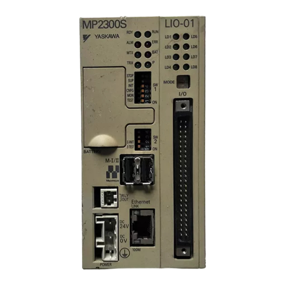
- Page 19 1.2 MP2300S Configuration 1.2.1 Basic Module Appearance 1.2 MP2300S Configuration The MP2300S is configured with one Basic Module and an optional slot. 1.2.1 Basic Module Appearance The following figure shows the external appearance of the Basic Module with metal fittings for attachment.
- Page 20 1.2 MP2300S Configuration 1.2.2 MP2300S Modules 1.2.2 MP2300S Modules The following table shows the names and specifications of the Basic Module and Optional Modules. Group Name Description Model Specifications MECHATROLINK-I and -II Interface Basic Module Basic Module MP2300S JAPMC-MP2300S-E Ethernet communications...
- Page 21 130 Ω M-I/II Other module such as other company's module thernet AnyWire LINK CC-Link 24 VDC A-net/A-link MECHATROLINK-II Terminating resistor 130 Ω YASKAWA SERVOPACK 200V YASKAWA SERVOPACK 200V SGDS-01A12A SGDS-01A12A CHARGE CHARGE VS mini V7 Repeater Servo Servo Servo Inverter Max.
- Page 22 For the details on the system configuration example, refer to 4.2.1 ( 1 ) System Layout Model. Use the connecting cables and connectors recommended by Yaskawa. Always check the device to be used and select the correct cable for the device.
- Page 23 1.4.1 MECHATROLINK-I/II Compatible Devices 1.4 MECHATROLINK Compatible Devices 1.4.1 MECHATROLINK-I/II Compatible Devices The following devices support MECHATROLINK communications and can be connected to the MECHATROLINK connectors of the MP2300S and SVB-01 Module. ( 1 ) SERVOPACKs and Inverters Drive Model...
- Page 24 1.4 MECHATROLINK Compatible Devices 1.4.2 MECHATROLINK-III Compatible Devices (cont’d) Model Description MECHATROLINK-I MECHATROLINK-II 64-point I/O Module JEPMC-IO2310 24 VDC, 64 inputs, 64 outputs (sink mode output) 64-point I/O Module JEPMC-IO2330 24 VDC, 64 inputs, 64 outputs (source mode output) Counter Module JEPMC-PL2900 Reversible counter, 2 channels Pulse Output Module...
- Page 25 1.5 Cables and Accessories 1.5.1 Cables 1.5 Cables and Accessories 1.5.1 Cables The following table shows the cables that can be connected to the MP2300S Basic Module and Optional Modules. Connector Module Application Model Specifications Name MP2300S Ethernet communication Ethernet –...
- Page 26 Optional JEPMC-OP2300S-E – Optional Cover Optional JEPMC-OP2300 Front cover for the empty slot 1.5.3 Software (Programming Tool) The MPE720, programming tool for MP2300S, is available. Name Model Remarks MPE720 CPMC-MPE720 (Ver. 5.38 or later) CD-ROM (1 disk) MPE720 Version 6 CPMC-MPE720 (Ver.
- Page 27 This chapter explains detailed specifications for the Basic Module and Optional Modules of the MP2300S. 2.1 Specifications - - - - - - - - - - - - - - - - - - - - - - - - - - - - - - - - - - - - - - - - - - - -2-2 2.1.1 General Specifications - - - - - - - - - - - - - - - - - - - - - - - - - - - - - - - - - - - - - - - - - - - - - - 2-2...
- Page 28 2.1 Specifications 2.1.1 General Specifications 2.1 Specifications 2.1.1 General Specifications Item Specifications Ambient Oper- ating Tempera- 0°C to 55°C ture Ambient Stor- age Tempera- -25°C to 85°C ture Ambient Oper- Environmental 30% to 95% (with no condensation) ating Humidity Conditions Ambient Stor- 5% to 95% (with no condensation) age Humidity...
- Page 29 2.1 Specifications 2.1.2 Product Specifications 2.1.2 Product Specifications The following table shows the product specifications of the MP2300S. Items MP2300S × × External Dimensions 64 mm 130 mm 108 mm Number of Optional Slots 1 slot Number of Basic 16 axes...
- Page 30 2.1 Specifications 2.1.3 Function Lists 2.1.3 Function Lists ( 1 ) PLC Function Specifications The following table shows the PLC function specifications. Item Specifications Control Method Sequence: High-speed and low-speed scan methods Programming Ladder diagram: Relay circuit Language Text-type language: Numeric operations, logic operations, etc. Two scan levels: High-speed scan and low-speed scan High-speed scan time setting: 0.5 to 32 ms (Integral multiple of MECHATROLINK communi-...
- Page 31 2.1 Specifications 2.1.3 Function Lists ( 2 ) Motion Control Function Specifications The following table lists the motion control function specifications for the MP2300S. Item Specifications Interface MECHATROLINK-I, MECHATROLINK-II Number of Controlled Axes/Module Up to 16 axes (up to 32 axes when an SVB Modules are mounted)
- Page 32 2.1.3 Function Lists (cont’d) Item Specifications MECHATROLINK-I MECHATROLINK-II • SERVOPACKs • SERVOPACKs SGD- SGDH- E + NS115 SGDB- SGDS- Applicable SERVOPACKs SGDH- E + NS100 SGDV- SGDS- SGDV- SGDV- SGDV- SGDV- SGDV- • Incremental Encoder Encoders • Yaskawa Absolute Encoder...
- Page 33 2.2 Basic Module This section describes the functions, the external appearance, the LED indicators, the setting switches, and the hard- ware specifications of the MP2300S Basic Module and also describes the virtual motion module (SVR). 2.2.1 Outline of Functions The Basic Module is an all-in-one, compact module that combines a power supply, a CPU, a SVB (built-in SVB) mod- ule and a 218IFA (Ethernet) module in one module.
- Page 34 2.2 Basic Module 2.2.2 External Appearance, LED Indicators, and Switch Settings 2.2.2 External Appearance, LED Indicators, and Switch Settings ( 1 ) External Appearance 23 S LED 1 indicators DTP switch (SW1) DTP switch (SW2) MECHATROLINK M-I/II connector RLY OUT connector LED 2 indicator thernet LINK...
- Page 35 2.2 Basic Module 2.2.2 External Appearance, LED Indicators, and Switch Settings ( 3 ) Switch Settings The DIP switch sets the operating conditions for the Basic Module when the power is turned ON. [ a ] SW1 STOP CNFG TEST Name Setting Operating Mode...
- Page 36 2.2 Basic Module 2.2.2 External Appearance, LED Indicators, and Switch Settings [ b ] SW2 Sets the Ethernet port condition and other operating conditions. The change of switch setting is invalid after the power is turned ON (read only when the module is initialized by soft- ware).
- Page 37 2.2.3 Specifications ( 1 ) Hardware Specifications The following table shows hardware specifications for the basic module: Item Specifications Classification Basic Module Name MP2300S Model Number JEPMC-MP2300S-E Input Voltage ± 24 VDC ( 20%) Input Current* 1 A max. (during input/output rating) 40 A max.
- Page 38 • Enables you to use as a standard interface with the engineering tool MPE720. In addition, provides a simple function for connecting with the engineering tool, allowing you to connect to MPE720 without the MP2300S IP address.
- Page 39 2.2 Basic Module 2.2.4 218IFA Module (Ethernet) ( 2 ) Specification of 218IFA Module The following table shows the specification of the 218IFA Module. Items Specifications 10Base-T/100Base-TX Communication Interface TCP/UDP/IP/ARP/ICMP Communication Protocol Maximum Number of Communication Connections 4+2 (I/O Message communication) Maximum Number of Communication Channels 4+2 (I/O Message communication) Write: 100W...
- Page 40 2.2 Basic Module 2.2.4 218IFA Module (Ethernet) uously received at an interval shorter than the startup interval of the MSG-RCV function. 2-14...
- Page 41 ( 3 ) Module Configuration Definition (a) Module Configuration Definition Screen Details Click MP2300S in the Controller area to display the details of the Basic Modules’ functions in the Module Details area. The cell No.2 provides a detailed definition of the 218IFA module.
- Page 42 218IFA Module Detailed Screen (a) Displaying the 218IFA Module Detailed Window The 218IFA Module Detailed Window is displayed by selecting MP2300S in the Controller area of the Module Con- figuration Window and double-clicking the cell No.2 in the Module Details field.
- Page 43 2.2 Basic Module 2.2.4 218IFA Module (Ethernet) (b) 218IFA Module Detailed Window The 218IFA Module Detailed Window is composed of Transmission Parameter and Status Tabs, and each tab is changed with a click. Parameter Setting Tab The Transmission Parameters Tab sets 218IFA transmission parameters of the 218IF module. The setting details are as follows: 2-17...
- Page 44 2.2 Basic Module 2.2.4 218IFA Module (Ethernet) Transmission Parameter Setting Items Sets local transmission parameters for the 218IFA module. The following table shows each setting item. Item Setting Range Details Default Sets the IP address for the 218IFA module. However, the follow- ing addresses are excluded: 0.0.0.1 to IP Address...
- Page 45 2.2 Basic Module 2.2.4 218IFA Module (Ethernet) Detailed Setting Screen of Transmission Parameter Setting Sets the engineering communication with MPE720 and the message communication. The following table shows each setting item. Item Setting Range Details Default Specify the port number for the 218IFA module used in the engineer- ing communication with MPE720.
- Page 46 TCP, Connect Type TCP: Transmission control protocol UDP: User datagram protocol Select an application layer protocol. Protocol Type Overview Extended Yaskawa’s Extended MEMOBUS protocol. MEMOBUS Extended MEMOBUS, MEMOBUS Yaskawa’s MEMOBUS protocol. MEMOBUS, Extended Ethernet I/F protocol for the sequencer (A...
- Page 47 2.2 Basic Module 2.2.4 218IFA Module (Ethernet) Item Setting Range Details Default Select a code type for the message communication data. Depending on protocol type, available codes are restricted as fol- lows: Code Protocol Type ASCII ASCII Extended Code ASCII √...
- Page 48 2.2 Basic Module 2.2.4 218IFA Module (Ethernet) Simple Setting Screen for Message Communication Graphically sets connection parameters for each connection. Basically, the same content as with message communication items in connection parameter setting can be set. When connection parameters are not yet set and this screen is opened, the default value for each connection will be automatically stored.
- Page 49 2.2 Basic Module 2.2.4 218IFA Module (Ethernet) Automatic Receive Setting Screen for Message Communication The automatic receive function can be enabled only for connections where the connection number = 1. The automatic receive function enables you to automatically run a function equivalent to the MSG-RCV function. The following table explains each setting item.
- Page 50 2.2 Basic Module 2.2.4 218IFA Module (Ethernet) The following table provides the valid setting items for each communication protocol type. Communication Protocol Type Setting Item Extended Non-proce- MODBUS/ MEMOBUS MELSEC MEMOBUS dure √ √ √ Readout of Input Relay – –...
- Page 51 2.2 Basic Module 2.2.4 218IFA Module (Ethernet) I/O Message Communication Item Connection Parameter Setting Sets connection parameters for I/O message communication. I/O message communication exchanges the data using I/O images with the remote equipment. The following table explains each setting item. Item Setting Range Details...
- Page 52 Select whether to update the output data in the I/O message commu- Output Disable Enable/disable enable nication. IW0000 to Set a start address of the input register of the MP2300S side for stor- IW xxxx MP2300S Head IW7FFF ing the data read from the remote equipment. Register Number...
- Page 53 2.2 Basic Module 2.2.4 218IFA Module (Ethernet) Easy Setting Window for I/O Message Communication Graphically adjusts the setting for the read/write connection parameters. Generally, the contents are similar to I/O message communication items in connection parameter setting. When the connection parameters are not yet set and this dialog box is opened, the default values for read/write connec- tion will be automatically stored.
- Page 54 2.2 Basic Module 2.2.4 218IFA Module (Ethernet) In addition, click the Default Button to set the default values for data code type, local I/O register setting, read/write size, and node read/write register setting according to the selected communication protocol type. The following table provides these default values.
- Page 55 2.2 Basic Module 2.2.4 218IFA Module (Ethernet) Status tab In the Status Tab, each setting for the transmission definition and transmission status of the 218IFA module is shown. The displayed contents are as follows: Transmission Parameter Item Item Displayed Content Default Station IP Address 000.000.000.000...
- Page 56 2.2 Basic Module 2.2.4 218IFA Module (Ethernet) Note: 1. Transmission status In online mode, displays the transmission status for each connection. Transmission Status State IDLE IDLE WAIT WAIT (waiting for connection) CONNECT CONNECT (capable of transmitting and receiving data) – Unused connection 2.
- Page 57 MP2300S: Only an SVB-01 Module can be mounted in optional slot. Including the MP2300S’s built-in SVB, a total of 32 axes can be controlled. • Synchronization between Modules is also supported, making it suitable for both synchronous control and interpolation across Modules.
- Page 58 2.2 Basic Module 2.2.5 Built-in SVB Module [ d ] System Configuration Example The following diagram shows a system configuration example. MP2300S SVB-01 24-VDC power supply MPE720 Ethernet MECHATROLINK-II MECHATROLINK-II Servo drive Servo drive MECHATROLINK support MECHATROLINK support input/output modules input/output modules Use the specified cables and connectors.
- Page 59 [ e ] Synchronization between Modules Overview MP2300S Machine Controller has a function that can synchronize hardware between the CPU and an optional module. This function enables MECHATROLINK communications in synchronization with high-speed scans. As a result, synchronization between a built-in SVB Module and an SVB-01 Module, or among multiple SVB-01 Modules, can be enabled.
- Page 60 2.2 Basic Module 2.2.5 Built-in SVB Module Timing At Which Modules Are Synchronized Modules are automatically synchronized when the power supply is turned OFF and ON again. Operation when High-speed Scan Cycle Is Changed MECHATROLINK communication with SVB Modules will continue even if the high-speed scan cycle is changed.
- Page 61 2.2 Basic Module 2.2.5 Built-in SVB Module ( 2 ) Specifications The specifications of built-in and optional SVB Modules are as follows. [ a ] Motion Control Function Item Details Number of Communication One line Lines Number of Communication 2 ports Ports (Connectors) Terminating Resistor JEPMC-W6022 terminator must be purchased separately.
- Page 62 2.2 Basic Module 2.2.5 Built-in SVB Module (cont’d) Item Details Single-send (communication cycle = transmission cycle) synchronous communication Transmission/communication error detection (hardware) provided. Communication Method Synchronous communication error detection (software) provided. Automatic recovery function not provided (recovery when alarm is cleared). I/O Registers Input/output using motion registers (synchronized on high-speed scan) Command Mode...
- Page 63 2.2 Basic Module 2.2.5 Built-in SVB Module [ b ] MECHATROLINK Communication Specifications Item MECHATROLINK-I MECHATROLINK-II Topology Transmission Media Twisted-pair cable Twisted-pair cable 50 m max. 50 m max. Transmission Distance (can be extended to 100 m by connecting (can be extended to 100 m by connecting repeaters) repeaters) Minimum Distance...
- Page 64 ( 3 ) Module Configuration [ a ] Module Configuration Window Click MP2300S in the Controller area to display the details of the basic module functions in the Module Details area. The cell No.3 provides a detailed definition of the built-in SVB module.
- Page 65 2.2 Basic Module 2.2.5 Built-in SVB Module The following table lists the items shown in the Module Configuration Window. Item Description Modification Slot Number Slot number Not possible Module Type Module detected in the slot Possible Controller Number Fixed to 01 Not possible Circuit Number Module circuit number...
- Page 66 2.2 Basic Module 2.2.5 Built-in SVB Module ( 4 ) MECHATROLINK Transmission Definition [ a ] How to Open the MECHATROLINK Transmission Definition Window In the Module Configuration Window, select the SVB Module in the Controller field and double-click the MECHA- TROLINK cell in the Module Details field.
- Page 67 2.2 Basic Module 2.2.5 Built-in SVB Module [ b ] MECHATROLINK Transmission Definition Window Details The MECHATROLINK Transmission Definition Window has four tabs: Transmission Parameters, Link Assign- ment, I/O Map, and Status. Click the tab to view each. Transmission Parameters Tab The parameters required to use the MECHATROLINK transmission system are displayed.
- Page 68 2.2 Basic Module 2.2.5 Built-in SVB Module (cont’d) Item Display during Self-configuration Options and Precautions on Settings Displays the maximum number of slave stations to which Number of the Master can retry transmission in one transmission Only for Master station. Set a number between cycle when the Master has not received a normal 0 and 7.
- Page 69 2.2 Basic Module 2.2.5 Built-in SVB Module Communication Cycle That Can be Set The communication cycle that can be set will differ depending on the communication type as follows. MECHATROLINK-II Communication 32-byte mode 17-byte mode Mode Communication 0.5 ms, 1 ms, 1.5 ms, or Cycle That Can be 0.5 ms or 1 ms 2 ms...
- Page 70 2.2 Basic Module 2.2.5 Built-in SVB Module Link Assignment Tab Page The data of the slave devices (MECHATROLINK connected devices such as SERVOPACK, inverter, and distrib- uted I/O) are displayed on the Link Assignment Tab. The items shown on the Link Assignment Tab are as follows. You can change the settings or delete the data station by station on this tab.
- Page 71 2.2 Basic Module 2.2.5 Built-in SVB Module I/O Map Tab The status allocated to I/O registers is displayed. The I/O Map Tab is used for monitoring (read-only). Do not change the displayed settings. [ c ] Status Tab Page The MECHATROLINK transmission status is displayed. The displayed settings cannot be changed. The items shown on the Status Tab are the same as those on the Link Assignment Tab except for STS.
- Page 72 [ a ] Opening the SVB Definition Window Open the SVB Definition Window by the following procedure. Select MP2300S in the Controller area, then double-click the slot number cell of the SVB Module in the Module Details field in the Module Configuration Window.
- Page 73 2.2 Basic Module 2.2.5 Built-in SVB Module Click the Fixed Parameters, Setup Parameters, or Monitor Tab to display the desired page. If the setting in Servo Type is switched from Rotary to Linear, or vice-versa, some of the displayed parameters will change.
- Page 74 In the MP2300S Basic Module, slot 4 in the default Module Configuration Window is for SVR. If the SVR is not used, MP2300S processing time can be reduced by setting the Module Type for SVR to UNDE- FINED in the Module Configuration Window.
- Page 75 The software limit function and machine lock function cannot be used with the SVR. The position error will always be ( 3 ) System Configuration Example The following figure shows an example system configuration using SVR. MP2300S CP U Virtual motion...
- Page 76 The default for the Selection of Operation Modes parameter is 1 (Axis Unused). The following table gives guidelines for the processing time required for each SVR axis. Command MP2300S 35 +14 × Number of axes (μs) 35 +36 × Number of axes (μs)
- Page 77 • Describing sequence control in motion language As a new programming method, a sequence program has been added to the MP2300S. A sequence program is a scan execution type program where a process is completed with one scan. It employs a text language similar to a motion program.
- Page 78 2.2 Basic Module 2.2.7 M-EXECUTOR Module (Motion Program Executor) ( 2 ) M-EXECUTOR Module Specification [ a ] Programs Capable of Registration in M-EXECUTOR The following table shows programs capable of registration in M-EXECUTOR. Program Type Number of Registrations Motion Program Startup Interrupt Disable...
- Page 79 ( 3 ) Module Configuration Definition (a) Details of Module Configuration Definition Window Click MP2300S in the Controller area to display the details of the basic module functions in the Module Details area. The cell No.5 provides a detailed definition of M-EXECUTOR.
- Page 80 2.2 Basic Module 2.2.7 M-EXECUTOR Module (Motion Program Executor) I/O Register Details An I/O register assigned to M-EXECUTOR is used to run a motion program and sequence program, and to monitor a sequence program. M-EXECUTOR I/O register details are as follows: M-EXECUTOR Input Register M-EXECUTOR Output Register M-EXECUTOR...
- Page 81 2.2 Basic Module 2.2.7 M-EXECUTOR Module (Motion Program Executor) ( 4 ) Detailed Screen This section describes the M-EXECUTOR detail screen. Program Definition Screen (M-EXECUTOR (list display) screen) The program definition screen allows you to register a motion or sequence program to run. Programs are executed according to the scan, in ascending numeric order.
- Page 82 2.2 Basic Module 2.2.7 M-EXECUTOR Module (Motion Program Executor) Execution type Sets the program execution type. Execution Type Program to Execute Execution Condition ---------- None None (select this to delete the definition) Sequence Program Power-up (during power-up, run only once) (startup) Sequence Program Periodical startup (run each time a low-sped scan is...
- Page 83 2.2 Basic Module 2.2.7 M-EXECUTOR Module (Motion Program Executor) Control Register Mapping Window The control register mapping screen sets a mapping register. A white cell can be set by the user, and a shaded cell cannot be set by the user. M-EXECUTOR Control register Displays an I/O register mapped to the M-EXECUTOR Module.
- Page 84 2.2 Basic Module 2.2.7 M-EXECUTOR Module (Motion Program Executor) Allocation register Data is exchanged between mapping and M-EXECUTOR control registers in real-time. Any register can be mapped to the mapping register. Registers that can be set as a Mapping Register Word type I, O, M (except the motion register) Allocation Contact interlock An allocation contact interlock is used to control the data exchange between the allocation register and...
- Page 85 2.2 Basic Module 2.2.7 M-EXECUTOR Module (Motion Program Executor) Program Execution Registration Screen (M-EXECUTOR (individual display) screen) Click the Individual Display Button in the M-EXECUTOR (list display) dialog box to display this dialog box. The items that can be set are similar to those in the program definition window and the control register mapping win- dow.
- Page 86 2.2 Basic Module 2.2.7 M-EXECUTOR Module (Motion Program Executor) ( 5 ) Execution Scheduling Programs registered in M-EXECUTOR are executed on the basis of their priorities (execution type). Programs registered in M-EXECUTOR are executed just before the ladder process. Power ON Sequence program (startup) Drawing A (startup process drawing)
- Page 87 2.2 Basic Module 2.2.7 M-EXECUTOR Module (Motion Program Executor) An execution example is as follows: • M-EXECUTOR program definition • Execution scheduling The following diagram shows the execution scheduling when set in the screen above. Startup SPM001 DWG.A High-speed scan cycle High-speed scan cycle High-speed scan SPM003...
- Page 88 2.3 Option Module 2.3.1 Option Module Overview List 2.3 Option Module This section provides an option module overview. For more information on its specifications, functions, connections, settings, etc., refer to the following documents separately. 2.3.1 Option Module Overview List Option Classification Module Overview Reference Manual...
- Page 89 (PI). As for when to input/output for Module digital I/O and pulse counter functions, input/output for each MP2200 high-speed (High)/ low-speed (Low) scan is carried out at a constant Machine Controller MP2300S cycle. Basic Module User’s Manual LIO-04/...
- Page 90 2.4 External Appearance 2.4.1 Basic Module 2.4 External Appearance The external appearance of the basic module is as follows: 2.4.1 Basic Module (42) Model nameplate DIN rail (35mm width) Relay connector (2P) Terminating resistor 734-YE102 for MECHATROLINK (attachment) Power connector (3P) (10: when DIN 721-203/026-000 (14: when released)
- Page 91 2.4 External Appearance 2.4.2 Basic Module with Metal Fittings 2.4.2 Basic Module with Metal Fittings (42) 111.5 2 x φ 5 holes Approx. 8 Units: mm when attached 2-65...
- Page 92 3.1.3 Space Required for Mounting MP2300S - - - - - - - - - - - - - - - - - - - - - - - - - - - - - - - - - 3-8...
- Page 93 Several types of DIN rails are available: with 7-mm to 15-mm gap from the mounting base as shown in the following diagram. If mounting a MP2300S using DIN rail with 10 mm gap, install a spacer on the rear of the MP2300S near the bottom to protect the MP2300S from vibration and shock.
- Page 94 Use the following procedure to attach the DIN rail mounting parts to the MP2300S and then mount the MP2300S to the DIN rail. Insert the DIN rails to the dotted line in the two slots on the rear of the MP2300S as shown in the fol- lowing figure.
- Page 95 300 mm or less 300 mm or less Hook the MP2300S to the top of the DIN rail (a), and then push the MP2300S towards the mounting base to secure it in place (b). Push the DIN rail mounting clips to lock them in place.
- Page 96 Attachment for mounting panel Insert two convex portions at the top of the panel mounting clamp into holes of the MP2300S case. Push the clamp as indicated by an arrow above onto the MP2300S case and use DIN fixing locks to fix MP2300S.
- Page 97 3.1 Mounting MP2300S 3.1.1 Method Push the MP2300S mounted clamp onto the mounting plate as shown in the figure below, and use four mounting screws to firmly secure the clamp. MP2300S M-I/II Mounting screw (M4 plus) Use the screwdriver with this portion of a driver not less than 10 cm.
- Page 98 3.1 Mounting MP2300S 3.1.2 MP2300S Mount Direction 3.1.2 MP2300S Mount Direction Be sure to mount the MP2300S using DIN rail or metal fittings. MP2300S View from front, when attached M-I/II...
- Page 99 3.1 Mounting MP2300S 3.1.3 Space Required for Mounting MP2300S 3.1.3 Space Required for Mounting MP2300S Install MP2300S so that enough space is left around it as shown in the following figure: Mount condition • Vertical direction: 40 mm or more •...
- Page 100 Use the following procedures to replace and add Optional Modules. ( 1 ) Preparations Create a backup data file. Use the MPE720 to save the MP2300S program on a computer (right-click the PLC, and select Transfer - All Files - From Controller to MPE720.) Remove the MP2300S.
- Page 101 3.1 Mounting MP2300S 3.1.4 Replacing and Adding Optional Modules Remove the Optional Module from the mounting base. Pull the top of the panel of the Optional Module towards you to remove it. A notch on the Optional Module will be visible from the gap in the cover. Hook the round knob on the battery cover, shown in the diagram, into the notch in the Optional Module.
- Page 102 Place the hole on the bottom of the panel of the Optional Module onto the hook on the bottom of the MP2300S. Next, hook the hole at the top of the panel of the Optional Module onto the hook at the top of the MP2300S.
- Page 103 3.2 Basic Module Connections 3.2.1 Connectors 3.2 Basic Module Connections 3.2.1 Connectors The following diagram shows the connectors for the Basic Module. MP2300S MECHATROLINK connector RLY OUT connector M-I/II Ethernet connector Power supply connector 3-12...
- Page 104 3.2 Basic Module Connections 3.2.2 Power Supply Connector 3.2.2 Power Supply Connector ( 1 ) Specifications, Pin Arrangement, and Connection Procedure Supply a 24-VDC to the MP2300S. Connect the power supply connector as shown in the diagram below. Connector Model Connector No. of...
- Page 105 Insert the wire into the opening and then close the opening by releasing the lever or removing the screwdriver. 3.2.3 MECHATROLINK Connectors MECHATROLINK connector is used to connect the MP2300S and the SERVOPACKs and distributed I/O via MECHATROLINK cables. ( 1 ) Specifications and Pin Arrangement...
- Page 106 3.2 Basic Module Connections 3.2.3 MECHATROLINK Connectors ( 2 ) Cables Name and Specification Model Number Length 0.5 m JEPMC-W6002-A5 JEPMC-W6002-01 MECHATROLINK Cable JEPMC-W6002-03 MECHATROLINK Connector – MECHATROLINK Connector JEPMC-W6002-05 10 m JEPMC-W6002-10 20 m JEPMC-W6002-20 30 m JEPMC-W6002-30 JEPMC-W6002-40 40 m 50 m JEPMC-W6002-50...
- Page 107 3.2 Basic Module Connections 3.2.3 MECHATROLINK Connectors ( 3 ) Cable Connections between the MP2300S and I/O Units and the MP2300S and SERVO- PACKs Use the MECHATROLINK cable JEPMC-W6002- or JEPMC-W6003- with a ferrite core for connection between the MP2300S and I/O units or SERVOPACKs.
- Page 108 1:N cable. The terminator must be provided by the user. 2. The shield wire can be connected as instructed in the SERVOPACK’s manual. However, the connec- tions shown in the above diagram is recommended when using the MP2300S in combination with a SVB-01 Module.
- Page 109 3.2 Basic Module Connections 3.2.3 MECHATROLINK Connectors ( 6 ) Connection Example between MP2300S, SERVOPACK, and IO2310 MP2300S YASKAWA JEPMC-IO2310 OUT1 OUT2 Terminator (terminating resistance: JEPMC-W6022) YASKAWA SERVOPACK 200V YASKAWA SERVOPACK 200V YASKAWA SERVOPACK 200V SGDS-01A12A SGDS-01A12A SGDS-01A12A CHARGE CHARGE...
- Page 110 3.2 Basic Module Connections 3.2.4 Ethernet Connector Details 3.2.4 Ethernet Connector Details Connects to a personal computer or HMI device by Ethernet (100Base-TX /10Base-T). ( 1 ) Ethernet Connector Specification and Pin Arrangement/ Indicator Light The following table provides the Ethernet connector specifications. Connector Model Connector Number...
- Page 111 3.2 Basic Module Connections 3.2.4 Ethernet Connector Details ( 3 ) Ethernet Connection Example The following are examples of Ethernet network connections via 10Base-TX cable: Connection Example 1 When using a repeater HUB: MP2300S MP2300S M-I/II Station Station 10Base-TX (Straight cable)
- Page 112 3.2 Basic Module Connections 3.2.4 Ethernet Connector Details The following are examples of Ethernet network connections via 100Base-TX cable: Connection Example 1 When using a repeater HUB: MP2300S MP2300S M-I/II Station Station 100Base-TX (straight cable) Up to 100 m Up to 100 m...
- Page 113 Attach a ferrite core in the manner described below: Ethernet : Attach it to the communication port side and the external equipment side of the MP2300S main unit. MECHATROLINK : Attach it only to the communication port side of the MP2300S main unit.
- Page 114 3.2 Basic Module Connections 3.2.5 RLY OUT Connector Details 3.2.5 RLY OUT Connector Details The RLY OUT connector is a terminal for outputting state and NO contact relay output. A circuit between terminals is short-circuited when RDY LED is lit, and opens when it is unlit. Note: A state when RDY LED is lit indicates that a controller is operating normally.
- Page 115 3.2 Basic Module Connections 3.2.5 RLY OUT Connector Details ( 3 ) RLY OUT Connection Example The following figure shows how to connect the RLY OUT connector: MP2300S RLY OUT output Power supply Operating normally: ON Error occurred: OFF 24 VDC...
- Page 116 3.2.6 System Connection Example 3.2.6 System Connection Example The following diagram shows a connection example of a system using the MP2300S. The following diagram shows a 200-VAC power supply example. Note: elect the SERVOPACK, 24-VDC power supply to use in accordance with the input power supply specifi- cation.
- Page 117 System Start Up and Easy Programming This chapter explains how to start up a model system using the programming tool MPE720 Ver.6. Note that the procedure for designing a mechanical system has been omitted here. 4.1 System Startup Overview - - - - - - - - - - - - - - - - - - - - - - - - - - - - - - - - - - -4-2 4.2 Preparation (step 1) - - - - - - - - - - - - - - - - - - - - - - - - - - - - - - - - - - - - - - -4-3 4.2.1 Wiring - - - - - - - - - - - - - - - - - - - - - - - - - - - - - - - - - - - - - - - - - - - - - - - - - - - - - - - - - - 4-3 4.2.2 Self Configuration - - - - - - - - - - - - - - - - - - - - - - - - - - - - - - - - - - - - - - - - - - - - - - - - - 4-5...
- Page 118 4.1 System Startup Overview 4.1 System Startup Overview This chapter, starting from section 4.2, provides detailed information on each step in the start-up procedure for a model system. The examples used explain how to run and check a program without external signals. The simple motion program which you create has three lines only, moving and stopping 150,000 pulses from the cur- rent position.
- Page 119 We use the following layout model to explain the startup of the model system. Prepare each device listed on the next page and connect them as shown in the figure below. ( 1 ) System Layout Model 24-VDC MECHATROLINK cable power supply SERVOPACK SERVOPACK MP2300S YASKAWA SERVOPACK 200V YASKAWA SERVOPACK 200V SGDS-A5F12A SGDS-A5F12A Terminator...
- Page 120 4.2 Preparation (step 1) 4.2.1 Wiring [ a ] Required Equipment Product Name Model Q’ty MP2300S JEPMC-MP2300S-E MECHATROLINK cable (0.5m) JEPMC-W6002-A5 Terminator (terminating resistor) JEPMC-W6022 Σ-III SERVOPACK SGDS-A5F12A Σ-III servomotor SGMAS-A5A2A21 Motor cable (3m) JZSP-CSM01-03 Encoder cable (3m) JZSP-CSP05-03 HUB (commercial product) LSW-TX-8EP MPE720 Ver.6...
- Page 121 Turn OFF the MP2300S 24-V power supply. Turn ON “INIT” and “CONFIG” of DIP switch (SW1) on the MP2300S main unit. Turn ON the 24-VDC power supply on the MP2300S main unit, and confirm the LED display changes as follows:...
- Page 122 4.2 Preparation (step 1) 4.2.3 Test Operation 4.2.3 Test Operation Confirm that the machine controller can command axis servo ON/OFF and jog operation. ( 1 ) Starting and Connecting MPE720 Ver.6 Launch MPE720 Ver.6 and click “1:Ethernet(LP)192.168.1.1” to connect to the controller. For more information on the communications settings, refer to Appendix F Simple Connection Function of the Engi- neering Tool.
- Page 123 4.2 Preparation (step 1) 4.2.3 Test Operation Axis Selection and Servo ON Set an axis number in the Axis Window and click the Enable (Servo ON) Button in the Test Run Window. Turning the servo ON allows you to manipulate the Jog/ Step Buttons.
- Page 124 4.2 Preparation (step 1) 4.2.3 Test Operation Jog Operation Click the Speed reference icon and set a speed reference value, and check that the axis rotates normally while the Forward Button or Reverse Button is pressed. The operation check of the first axis is complete. Press the Axis ...
- Page 125 4.3 Programming (step 2) 4.3.1 Programming Procedure 4.3 Programming (step 2) This section describes the procedure from creating to saving a motion program. 4.3.1 Programming Procedure Click the Motion Tag in the subwindow. The motion program subwindow will appears. When you double-click Motion Program and there is not any group definition, the group definition screen will be shown.
- Page 126 4.3 Programming (step 2) 4.3.1 Programming Procedure Editing Motion Program Use the command input assist feature to insert INC and MOV Commands into the motion program. The command input assist feature is made accessible by right-clicking the mouse on the Motion Editor Window. •...
- Page 127 4.4 Executing Motion (step 3) 4.4.1 Registering Program Execution 4.4 Executing Motion (step 3) 4.4.1 Registering Program Execution Click the Execution Registration Icon. Note: This motion program was made with the assumption that Enable (Servo ON) was selected in step 2 of 4.2.3 ( 2 ) Operating Manually in the Test Operation Screen.
- Page 128 • Registering a program execution enables the M-EXECUTOR definition. The MP2300S automatically controls the motion program, so be aware that problems might occur if you change registers which are registered in ladder or sequence programs while running the motion program.
- Page 129 This section explains how to start a motion program created in 4.3 Programming (step 2) from external signals. Note that in this section, we show an example which substitutes a touch panel for the external signal. 24-VDC MECHATROLINK cable power supply SERVOPACK SERVOPACK MP2300S YASKAWA SERVOPACK 200V YASKAWA SERVOPACK 200V A real machine uses an SGDS-01A12A...
- Page 130 4.5 Starting Motion Program from an External Signal 4.5.2 Required Equipment Mapping of the touch panel manufactured by Digital Electronics Corp. MP2300S Name Mapping Category Description Operation Start MB5000 Control signal Starts up a motion program Stop MB5002 Control signal...
- Page 131 4.5 Starting Motion Program from an External Signal 4.5.3 Creation Procedure 4.5.3 Creation Procedure Creating a Sequence Program Now create a sequence program which copies the M register content mapped to “ Servo (ON/OFF)” and “ Axis Alarm Reset” Buttons on the touch panel to the relevant registers in the motion setting parameter of the built-in SVB module.
- Page 132 4.5 Starting Motion Program from an External Signal 4.5.3 Creation Procedure Registering Program Execution • A Task Allocation Dialog Box will appear. • Click the Set Button to set a program definition in the M-EXECUTOR Window. → Then register the MPM001, SPM001 executions. For more information on how to set the M-EXECUTOR Window, refer to 2.2.7 M-EXECUTOR Module (Motion Program Executor).
- Page 133 FLASH Save When all settings are completed, click the FLASH Save Icon to save the data to the flash memory. Operation Check Turn ON MP2300S power again and press “ Servo” and “ Start” on the panel screen. Then check that the motion program starts and the two-axes motor begins to operate to change the current posi- tion of the axis.
- Page 134 5.4.2 Definition Information Updated with Self-Configuration - - - - - - - - - - - - - - - - - - - - - - 5-50 5.5 Precaution on Using MP2300S - - - - - - - - - - - - - - - - - - - - - - - - - - - - - - 5-53 5.5.1 Precautions when User Definition File is Configured/Changed - - - - - - - - - - - - - - - - - 5-53...
- Page 135 5.1 Startup Sequence and Basic Operation 5.1.1 DIP Switch Settings 5.1 Startup Sequence and Basic Operation This section describes the MP2300S startup sequence and basic operation together with the DIP switch settings, self- diagnosis at startup, and LED indicator patterns. 5.1.1 DIP Switch Settings Set the DIP switch (SW1) on the Basic Module to control operations of the startup sequence.
- Page 136 5.1 Startup Sequence and Basic Operation 5.1.2 Startup Sequence 5.1.2 Startup Sequence The startup sequence for the MP2300S from the moment when the power has been turned ON is shown in the follow- ing flowchart. Power ON Startup self-diagnostics (1)
- Page 137 First scan processing is executed once DWG.A has been completed and the high-speed or low-speed scan time has elapsed. System I/O are executed from the first scan. ( 4 ) Operation Stop MP2300S stops motion control operation when the STOP switch is ON (STOP) and in the following circumstances. Cause Restart method Power supply turned OFF Turn ON the power again.
- Page 138 5.2.1 Types and Execution Timing of User Program 5.2 User Programs User programs for executing machine control using the MP2300S include ladder programs and motion programs. This section describes the basic operation and other information about user programs. For programming details, refer to the following manuals.
- Page 139 • Program number of Sequence program SPM , SPS The MP2300S can execute up to 16 motion programs simultaneously. An alarm (no system work error) will occur if 17 or more programs are executed simultaneously. • No system work error: Bit E of the leading word in the MSEE work registers...
- Page 140 5.2 User Programs 5.2.2 Motion Programs This section explains the Group Definition screen. No. of Group Set a number for the operation as a group. Set it to 1 for the operation as one group. Set it to the number of groups for the operation with multiple groups. Group Name Define a group name.
- Page 141 5.2 User Programs 5.2.2 Motion Programs Axis No. Set an axis number for the used axis. The axis number can be checked in the detailed screen of the used motion module. Axis number Double-click Logical Axis Name Define a name for the specified axis number. The name defined here is used when programming a motion program.
- Page 142 5.2 User Programs 5.2.2 Motion Programs ( 2 ) How to Run a Motion Program The following two methods are available for running a motion program. • Registering it to the M-EXECUTOR program execution definition • Executing it using a MSEE command from a ladder program of H drawing Now, this section explains each way to run a motion program: [ a ] Registering it to the M-EXECUTOR Program Execution Definition After creating a motion program, register it in the M-EXECUTOR program execution definition screen.
- Page 143 5.2 User Programs 5.2.2 Motion Programs [ b ] Executing H Drawings by MSEE Command Motion programs are always called from H drawings using the MSEE command (motion program call command). Motion programs can be called from any parent, child, or grandchild drawing in an H drawing. The following figure shows an example of motion program execution.
- Page 144 5.2 User Programs 5.2.2 Motion Programs ( 3 ) How to Designate a Motion Program The following two methods are available for designating a motion program. • Using a direct designation to invoke a motion program • Using a indirect designation to invoke a motion program Now, this section explains each way to designate a motion program.
- Page 145 5.2 User Programs 5.2.2 Motion Programs [ b ] Using an Indirect Designation to Call a Motion Program An indirect designation method designates a motion program to call using a register. In this method, a program (MPM ) coinciding with value stored in the register is called. A motion program registered in the M-EXECUTOR program execution definition Select Indirect for the Setting.
- Page 146 5.2 User Programs 5.2.2 Motion Programs ( 4 ) Work Register Configure and monitor a motion program via a work register. The work register constitution for motion programs registered in the M-EXECUTOR program execution definition dif- fers from that for motion programs referenced by a MSEE command from a ladder program. The work register constitution in each case is as follows: A motion program registered in the M-EXECUTOR program execution definition The work register is assigned to a M-EXECUTOR control register.
- Page 147 5.2 User Programs 5.2.2 Motion Programs [ a ] Status Flag of a Motion Program The motion program status flag shows the execution status of the motion program. The following table shows details of status flag. Table 5.1 Status Flag Bit No.
- Page 148 5.2 User Programs 5.2.2 Motion Programs [ b ] Control Signal Program control signals (e.g., program operation start requests and program stop requests) need to be entered to exe- cute the motion program. The following types of signals for controlling motion programs are available. Table 5.2 Control Signals Bit No.
- Page 149 5.2 User Programs 5.2.2 Motion Programs Timing Chart for Motion Program Control Signals The following figure shows an example of a timing chart for motion program control signals. Program Operation Start Request Control signal: Operation start request Status: Operating Distribution Pause Request Control signal: Operation start request Control signal: Pause request...
- Page 150 5.2 User Programs 5.2.2 Motion Programs [ d ] System Work Number The system work number n (setting range: 1 to 16) used when executing motion programs is set by the MSEE work registers. This system work number is enabled only when the motion program control signal bit D (system work number setting) is ON.
- Page 151 5.2 User Programs 5.2.2 Motion Programs ( 5 ) How to Operate a Work Register The way to operate a work register of a motion program registered in the M-EXECUTOR program execution definition differs from that of a motion program referenced by a MSEE command from a ladder program. The way to operate it in each case is shown as follows: [ a ] A motion program registered in the M-EXECUTOR program execution definition When a motion program is registered in M-EXECUTOR program execution definition, select one from the following...
- Page 152 5.2 User Programs 5.2.2 Motion Programs A Way to Immediately Control a Motion Program from External Equipment M-EXECUTOR has a function which allocates any register to an M-EXECUTOR control register. Using this function allows you to automatically exchange data between an M-EXECUTOR control register and an I/O register connected to an external equipment.
- Page 153 5.2 User Programs 5.2.2 Motion Programs A Way to Control a Motion Program via a Sequence or Ladder Program Without using the allocating function of the above mentioned M-EXECUTOR control register, controls a motion program via a sequence or ladder program. To use this execution processing, save the blank Allocation register and the blank Allocation interlock contact as a blank.
- Page 154 5.2 User Programs 5.2.2 Motion Programs Example using a ladder program 5-21...
- Page 155 5.2 User Programs 5.2.2 Motion Programs [ b ] A motion program referenced by a MSEE command from a ladder program When a motion program is referenced by a MSEE command from a ladder program, control the motion program via a sequence or ladder program.
- Page 156 5.2 User Programs 5.2.2 Motion Programs Example using a ladder program 5-23...
- Page 157 5.2 User Programs 5.2.2 Motion Programs ( 6 ) Monitor the motion program execution information using S register Using S register (SW03200 to SW04191) allows you to monitor the motion program execution information. The way to monitor the execution information for a motion program registered in the M-EXECUTOR program execu- tion definition differs from that for a motion program referenced by an MSEE command from a ladder program.
- Page 158 5.2 User Programs 5.2.2 Motion Programs Register Areas for Motion Program Execution Information Executing program number Motion program execution information SW03200 SW03200 Program number used by work 1 Executing program number (No. of main program currently Program number used by work 2 SW03201 executing) Program number used by work 3...
- Page 159 5.2 User Programs 5.2.2 Motion Programs Details of Program Information Used by Work n Program information used by work n Program status Program control signal Executing program number Executing block number Parallel 0 information Error code Parallel 1 information Parallel 2 information Parallel 3 information Parallel 4 information Parallel 5 information...
- Page 160 5.2 User Programs 5.2.3 Sequence Program 5.2.3 Sequence Program A sequence program is a program described with motion language of text format. The following table shows two types of sequence programs. Designation Category Features Number of Programs Method Up to 256 programs of the following types can Calling from the M-EXECUTOR Main program be created:...
- Page 161 5.2 User Programs 5.2.3 Sequence Program ( 2 ) How to Designate a Sequence Program You can only designate a sequence program directly. Indirect designation is unavailable. Use the program number (SPM ) when designating a sequence program to execute. Sequence program SPM001 M-EXECUTOR program execution definition...
- Page 162 5.2 User Programs 5.2.3 Sequence Program ( 3 ) Work Register Monitor a sequence program through a work register. A work register, similar to the motion program registered in M-EXECUTOR, has status flags in the M-EXECUTOR control register. The following table shows the work register configuration of the sequence program. Work Register Content Status...
- Page 163 5.2 User Programs 5.2.4 Ladder Drawings (DWG) 5.2.4 Ladder Drawings (DWG) ( 1 ) Types of Drawings Ladder programs are managed in units of ladder drawings, which are identified by drawing numbers. These drawings form the basis of user programs. Ladder drawings include parent drawings, child drawings, grandchild drawings, and operation error processing draw- ings.
- Page 164 5.2 User Programs 5.2.4 Ladder Drawings (DWG) ( 2 ) Execution Control of Drawings [ a ] Execution Control The following table shows when each drawing is executed based on the order of priority. Power ON DWG.A (initial processing drawing) Operation error Interrupt signal Each high-speed scan...
- Page 165 5.2 User Programs 5.2.4 Ladder Drawings (DWG) [ c ] Hierarchical Structure of Drawings Each processing program is made up of parent drawings, child drawings, and grandchild drawings. Parent drawings cannot call child drawings from a different type of drawing and child drawings cannot call grandchild drawings from a different type of drawing.
- Page 166 5.2 User Programs 5.2.4 Ladder Drawings (DWG) [ d ] Drawing Execution Processing Method The execution processing of hierarchical drawings are performed by calling lower-level drawings from higher-level drawings. The following figure shows the execution processing for drawings, using DWG.A as an example. System programs are started according to execution conditions.
- Page 167 5.2 User Programs 5.2.4 Ladder Drawings (DWG) ( 3 ) Functions Functions are executed by calling them from parent, child, or grandchild drawings using the FUNC command. Functions can be called from any drawing, and the same function can be called at the same time from different types of drawings and from different levels of drawings.
- Page 168 User’s Manual (manual number: SIEP C880700 30) for details. 4. S and M register data has a battery backup to ensure the data is held even if the MP2300S power is turned OFF and ON. Other register data is saved to flash memory, so when the MP2300S power is turned OFF to ON, data saved to flash memory is read and data not saved to flash memory is lost.
- Page 169 5.3 Registers 5.3.1 Types of Registers ( 2 ) Function Registers The following table shows the registers that can be used with each function. Type Name Specification Method Range Details Characteristics Input to functions Bit input: XB000000 to XB00000F Function input regis- XW00000 to XB, XW, XL, XFnnnnn Integer input: XW00001 to XW00016...
- Page 170 5.3 Registers 5.3.1 Types of Registers ( 3 ) Register Ranges in Programs The following figure shows DWG programs, function programs, and register call ranges. Common DWG registers DWG. H (drawing) System registers Program (SB, SW, SL, SFnnnnn) 1000 steps max. Data registers (MB, MW, ML, MFnnnnn) DWG registers...
- Page 171 5.3 Registers 5.3.2 Data Types 5.3.2 Data Types There are five kinds of data: Bit, integer, double-length integer, real number, and address data. Each is used differently depending on the application. Address data, however, is used only inside functions when specifying pointers. The following table shows the types of data.
- Page 172 5.3 Registers 5.3.3 How to Use Subscripts i, j 5.3.3 How to Use Subscripts i, j Two type of registers (i, j) are available as dedicated registers to modify the relay and register numbers. Both i and j have the same function. They are used when you want to handle a register number as a variable. An example for each register data type is given as explanation.
- Page 173 5.3 Registers 5.3.4 Register Designation 5.3.4 Register Designation Registers can be specified directly by register number or by symbol (register name). A combination of both of these register designation methods can be used in ladder programs. When using the symbol specification method, the relationship between symbols and register numbers must be defined. The following table shows the register specification methods.
- Page 174 5.4 Self-configuration 5.3.4 Register Designation 5.4 Self-configuration The self-configuration function automatically recognizes the Optional Modules mounted to the MP2300S Basic Mod- ule and all slave data for slaves connected to the MECHATROLINK network, and automatically generates a definition file. Self-configuration greatly simplifies the procedure needed to start the system.
- Page 175 Turn OFF the 24-VDC power supply to the MP2300S. STOP 2. Set the DIP switch. INIT Set the switches INIT and CNFG of the DIP switch SW1 on the MP2300S CNFG Basic Module to ON. TEST 3. Turn ON the power supply.
- Page 176 INIT Switch and RAM Data RAM data will be cleared if the INIT switch of the DIP switch on the MP2300S Basic Module is ON and the power is turned ON. Flash memory data is read and overwritten when the INIT switch is OFF and the power is turned ON. Therefore, to protect RAM data, always save data to the MP2300S flash memory before turning OFF the power when writing or editing programs.
- Page 177 This section explains each way to execute the self-configuration. [ a ] Self-configuration for All the Modules By performing the following operation, the self-configuration for MP2300S basic and option modules is executed. Before performing the operation, turn ON the power supply of equipment such as SERVOPACK.
- Page 178 5.4 Self-configuration 5.4.1 How to Execute Self-Configuration If the following warning message is shown after performing step 4, the module configuration definitions for CPU and MPE720 may differ from each other. Continue to perform step 6. When the message is not shown, go to step 9.
- Page 179 5.4 Self-configuration 5.4.1 How to Execute Self-Configuration Click Start to read the module configuration definition from a controller. Click the Save & FLASH Save Button to flash save the definition information. Check that the definition is successfully created in the Module Configuration Window. 5-46...
- Page 180 5.4 Self-configuration 5.4.1 How to Execute Self-Configuration [ b ] Self Configuration of Each Module If modules or devices are added, self-configuration can be executed separately for the Module (port) that has been changed. By performing the following operation, self-configuration will be executed for the selected slot. Before performing the operation, turn ON the power supply of devices such as SERVOPACK.
- Page 181 5.4 Self-configuration 5.4.1 How to Execute Self-Configuration While running the self-configuration, the following message is shown. If the following warning message is shown after performing step 4, the module configuration definitions for CPU and MPE720 may differ from each other. Continue to perform step 6. When the message is not shown, go to step 9.
- Page 182 5.4 Self-configuration 5.4.1 How to Execute Self-Configuration Click Individual, and only check Module Configuration. Click Start to read the module configuration definition from a controller. Click the Save & FLASH Save Button to flash save the definition information. In the Module Configuration Definition Window, check that the definition has been created. 5-49...
- Page 183 5.4.2 Definition Information Updated with Self-Configuration Now, the definition information updated during executing the self-configuration and the module configuration defini- tion example based on the module combination are as follows: ( 1 ) Definition Data of MP2300S Basic Module [ a ] I/O Allocations Item Allocation •...
- Page 184 Number of Transmit Bytes Communication Cycle 1 ms 1 ms 2 ms Number of Slave Stations Note: To use MP2300S/SVB as a Slave, before executing the self-configuration, the parameter setting for MECHATROLINK transmission definition must be set to Slave in MPE720. 5-51...
- Page 185 5.4 Self-configuration 5.4.2 Definition Information Updated with Self-Configuration [ d ] SVR Definition Type Name Allocation Selection of Operation Modes Axis unused Function Selection Flag 1 0000h Reference Unit Selection pulse Number of Digits below Decimal Point Travel Distance per Machine Rotation 10000 reference unit Servo Motor Gear Ratio 1 rev (rotation)
- Page 186 When a system setting, scan time setting, or module configuration definition is configured/changed, be sure to use MPE720 to flash save it. Note that when the MP2300S power supply is turn ON again without flash saving, the config- ured/changed data may be lost.
- Page 187 • Always check to make sure that the mounted Module is the one that is defined. • Be sure to save any new settings or changes to flash memory. • After the settings or changes have been completed, turn the power supply to the MP2300S OFF and ON. 5-54...
- Page 188 Note: If the scan time is set too close to the maximum execution time for the scan, the refresh time for the screen on the MPE720 will be very slow and communication timeouts may occur. If the maximum execu- tion time exceeds the scan time set value, a watchdog timer timeout error will occur and the MP2300S system will stop.
- Page 189 5.5 Precaution on Using MP2300S 5.5.3 Setting and Changing the Scan Time ( 2 ) Scan Time Set Value Examples 0.8-ms Maximum Scan Time and 1-ms Communication Cycle (MECHATROLINK-II Only) High-speed (or low-speed) scan set value ≥ 1.25 × 0.8 (= 1 ms) High-speed (or low-speed) scan set value = 1 ms, 2 ms, 3 ms, etc.
- Page 190 6.2 Communication with Other MP Series - - - - - - - - - - - - - - - - - - - - - - - - - -6-3 6.2.1 When the MP2300S Acts as Slave (automatic receive function is used) - - - - - - - - - - - 6-3 6.2.2 When the MP2300S Acts as Slave...
- Page 191 The MP2300S (slave) creates ladder programs using the MSG-RCV multiple masters is function. possible. ⇒ Refer to 6.2.2 When the MP2300S Acts as Slave (ladder program which uses a MSG-RCV function) Other MP Series Only the holding reg- Uses the Extended MEMOBUS communication protocol.
- Page 192 This chapter explains communications when an MP2300S acts as a slave and a master respectively. When the MP2300S acts as a slave, this chapter explains communications using an automatic receive function and a ladder program with the MSG-RCV function.
- Page 193 6.2.1 When the MP2300S Acts as Slave (automatic receive function is used) Setting Example The following figure illustrates how the content of the MP2300S (master) holding register (MW00000 to MW00099) is written into the MP2300S (slave) holding register (MW00000 to MW00099).
- Page 194 6.2 Communication with Other MP Series 6.2.1 When the MP2300S Acts as Slave (automatic receive function is used) ( 1 ) How to Set up the MP2300S Side If the setting of transmission parameters (IP address, subnet mask) is already completed, start from step 3.
- Page 195 6.2 Communication with Other MP Series 6.2.1 When the MP2300S Acts as Slave (automatic receive function is used) Set a communication setting in the Message Communication Easy Setting Window. How to set up in the Message Communication Easy Setting Window When automatic receive is used, select “1”...
- Page 196 6.2 Communication with Other MP Series 6.2.1 When the MP2300S Acts as Slave (automatic receive function is used) Click Yes in the confirmation dialog of the parameter setting. Caution Note that when a parameter with the same connection number is already set and you click Yes in the confirmation dialog of the parameter setting, the setting will be overwritten by the parameter configured in the Message Communication Easy Setting Window.
- Page 197 2.2.4 ( 4 ) (b) Automatic Receive Setting Screen for Message Communication . Now, the automatic receive function is set up when the MP2300S acts as a slave. Caution When any transmission or connection parameter is changed, the change will be reflected after FLASH has been saved and the...
- Page 198 6.2 Communication with Other MP Series 6.2.1 When the MP2300S Acts as Slave (automatic receive function is used) ( 2 ) How to Set up the Remote Device (MP2300) to Be Connected If the setting of transmission parameters (IP address, subnet mask) is already completed, start from step 3.
- Page 199 Set Local Port to the port number used in the MP2300 side (“10001,” for example). Set Node IP Address to the IP address configured in the MP2300S side. Set Node Port to the port number configured in the MP2300S side (“10001,” for example). Select Connect Type (TCP, for example).
- Page 200 6.2 Communication with Other MP Series 6.2.1 When the MP2300S Acts as Slave (automatic receive function is used) Create a ladder program with a message transmit function (MSG-SND). A ladder program for transmitting messages to/from the remote equipment (MP2300) side is shown as follows: Message transmit function (MSG-SND) Required for transmitting messages.
- Page 201 6.2 Communication with Other MP Series 6.2.1 When the MP2300S Acts as Slave (automatic receive function is used) Input/output definitions for message transmit functions The input/output definitions for the message transmit function are explained as follows: Table 6.1 Input/Output Definitions for Message Transmit Functions...
- Page 202 6.2 Communication with Other MP Series 6.2.1 When the MP2300S Acts as Slave (automatic receive function is used) Parameter list setting example for the message transmit function An example of a parameter list setting when writing 100 words of data from MW00000 to the destination using the connection with a connection number = 1 follows: Table 6.2 Sample Parameter List Setting (parameter list start address Param=DA00000)
- Page 203 6.2 Communication with Other MP Series 6.2.1 When the MP2300S Acts as Slave (automatic receive function is used) Example of Using the Message Transmit Function in a Ladder Program Here is one example of the message transmit function through Ethernet (218IF).
- Page 204 6.2 Communication with Other MP Series 6.2.1 When the MP2300S Acts as Slave (automatic receive function is used) Continued from the previous page Continued on the next page 6-15...
- Page 205 6.2 Communication with Other MP Series 6.2.1 When the MP2300S Acts as Slave (automatic receive function is used) Continued from the previous page The communication setting and the ladder program creation are now finished, when MP2300 acts as a master.
- Page 206 To communicate with more than one master, use a ladder program with a message receive function (MSG-RCV) at the MP2300S end. You can use the message receive function (MSG-RCV) as well as the automatic receive function by keeping connections separate from each other.
- Page 207 6.2 Communication with Other MP Series 6.2.2 When the MP2300S Acts as Slave (ladder program which uses a MSG-RCV function) Setting Example The following figure illustrates one example of writing the contents of the MP2300 (master) holding register (MW00100 to MW00199) into the MP2300S (slave) holding register (MW00100 to MW00199).
- Page 208 6.2 Communication with Other MP Series 6.2.2 When the MP2300S Acts as Slave (ladder program which uses a MSG-RCV function) ( 1 ) How to Set up the MP2300S Side If the setting of transmission parameters (IP address, subnet mask) is already completed, start from step 3.
- Page 209 6.2 Communication with Other MP Series 6.2.2 When the MP2300S Acts as Slave (ladder program which uses a MSG-RCV function) Click the Easy Setting Button in the Message Communication area of the connection parameter set- ting. Set a communication setting in the Message Communication Easy Setting Window.
- Page 210 6.2 Communication with Other MP Series 6.2.2 When the MP2300S Acts as Slave (ladder program which uses a MSG-RCV function) Caution When message functions (MSG-SND, MSG-RCV) are used with the connection number 01, disable the automatic receive func- tion. If message functions are used while the automatic receive function is enabled, communications will not function properly.
- Page 211 6.2.2 When the MP2300S Acts as Slave (ladder program which uses a MSG-RCV function) Create a ladder program with a message receive function (MSG-RCV) in it. An example of a ladder program for receiving messages in the MP2300S side is as follows: Message receive function (MSG-RCV) Required for receiving messages.
- Page 212 6.2 Communication with Other MP Series 6.2.2 When the MP2300S Acts as Slave (ladder program which uses a MSG-RCV function) Input/output definition contents for message receive functions The input/output definition content for message receive function is as follows: Table 6.4 Input/Output Definitions for Message Receive Functions...
- Page 213 6.2 Communication with Other MP Series 6.2.2 When the MP2300S Acts as Slave (ladder program which uses a MSG-RCV function) Parameter list setting example for message receive function An example of a parameter list setting when receiving messages from a transmit source using the connection with a connection number = 2 follows: Table 6.5 Parameter List Setting Example (parameter list start address Param=DA00000)
- Page 214 6.2 Communication with Other MP Series 6.2.2 When the MP2300S Acts as Slave (ladder program which uses a MSG-RCV function) Example of Using the Message Receive Function in a Ladder Program Here is an example of the message receive function through Ethernet (218IFA).
- Page 215 6.2 Communication with Other MP Series 6.2.2 When the MP2300S Acts as Slave (ladder program which uses a MSG-RCV function) Continued from the previous page The communication setting and the ladder program creation are now finished, when the MP2300S acts as a slave. 6-26...
- Page 216 6.2 Communication with Other MP Series 6.2.2 When the MP2300S Acts as Slave (ladder program which uses a MSG-RCV function) ( 2 ) How to Set up the Remote Device (MP2300) to Be Connected If the setting of transmission parameters (IP address, subnet mask) is already completed, start from step 3.
- Page 217 6.2 Communication with Other MP Series 6.2.2 When the MP2300S Acts as Slave (ladder program which uses a MSG-RCV function) Set transmission parameters. How to set up transmission parameters Set IP Address (“192.168.001.001,” for example). Click Edit, and then click Local Station: TCP/IP Setting in the Engineering Manager Window.
- Page 218 Set Local Port (the port number “10002” used in the MP2300 side, for example). Set the Node IP Address (the IP address “192.168.001.001” configured in the MP2300S side, for example). Set the Node Port (the port number “10002” configured in the MP2300S side, for example).
- Page 219 6.2.2 When the MP2300S Acts as Slave (ladder program which uses a MSG-RCV function) Create a ladder program containing a message transmit function (MSG-SND). An example of a ladder program for transmitting messages in the remote device (MP2300S) side follows: Message transmit function (MSG-SND) Required for transmitting messages.
- Page 220 6.2 Communication with Other MP Series 6.2.2 When the MP2300S Acts as Slave (ladder program which uses a MSG-RCV function) Input/output definitions contents for message transmit functions The input/output definition content for the message transmit function is as follows: Table 6.6 Input/Output Definitions for Message Transmit Functions...
- Page 221 6.2 Communication with Other MP Series 6.2.2 When the MP2300S Acts as Slave (ladder program which uses a MSG-RCV function) Parameter list setting for the message transmit function An example of a parameter list setting when reading 100 words of data from MW00100 from the destination using the connection with a connection number = 2 follows: Table 6.7 Parameter List Setting Example (parameter list start address Param=DA00000)
- Page 222 6.2 Communication with Other MP Series 6.2.2 When the MP2300S Acts as Slave (ladder program which uses a MSG-RCV function) Example of Using the Message Transmit Function in a Ladder Program Here is one example of the message transmit function through Ethernet (218IF).
- Page 223 6.2 Communication with Other MP Series 6.2.2 When the MP2300S Acts as Slave (ladder program which uses a MSG-RCV function) Continued from the previous page Continued on the next page 6-34...
- Page 224 6.2 Communication with Other MP Series 6.2.2 When the MP2300S Acts as Slave (ladder program which uses a MSG-RCV function) Continued from the previous page The communication setting and the ladder program creation are now finished, when MP2300 acts as a master.
- Page 225 6.2 Communication with Other MP Series 6.2.3 When the MP2300S Acts as Master (I/O message communication function is used) 6.2.3 When the MP2300S Acts as Master (I/O message communication function is used) This section explains how to communicate with the MP2300 message receive function (MSG-RCV) using the MP2300S I/O message communication function.
- Page 226 The following figure illustrates one example of reading the contents of the holding register (MW00200 to MW00299) of MP2300 (slave) into an input register (IW0000 to IW0063) of MP2300S (master) and writing the contents of an out- put register (OW0064 to OW00C7) of MP2300S (master) into a holding register (MW00300 to MW00399) of MP2300 (slave).
- Page 227 6.2 Communication with Other MP Series 6.2.3 When the MP2300S Acts as Master (I/O message communication function is used) ( 1 ) How to Set up the MP2300S Side If the setting of transmission parameters (IP address, subnet mask) is already completed, start from step 3.
- Page 228 6.2 Communication with Other MP Series 6.2.3 When the MP2300S Acts as Master (I/O message communication function is used) Set a communication setting in the I/O Message Communication Easy Setting Window. How to set up in the I/O Message Communication Easy Setting Window Set Port No.
- Page 229 Set the register type and start address (Read Reg) of the remote device (MP2300) read by the MP2300S (“MW00200,” for example).
- Page 230 6.2 Communication with Other MP Series 6.2.3 When the MP2300S Acts as Master (I/O message communication function is used) ( 2 ) How to Set up the Remote Device (MP2300) to Be Connected When the setting of transmission parameters (IP address, subnet mask) is already completed, start from step 3.
- Page 231 Set Local Port (the port number “10005, 10006” used in the MP2300 side, for example). Set Node IP Address (the IP address “192.168.001.001” configured in the MP2300S side, for example). Set Node Port (the port number “10005, 10006” configured in the MP2300S side, for example).
- Page 232 Required for receiving messages. Message reception is carried out by inputting and executing this message receive function in a ladder program. In addition, in order to support Read and Write by MP2300S, two message receive functions should be provided. Here, the input item and parameters (Communication buffer channel number and Connection number) of the message receive function need to accord with the MP2300S side settings.
- Page 233 6.2 Communication with Other MP Series 6.2.3 When the MP2300S Acts as Master (I/O message communication function is used) Input/output definition contents for message receive functions The input/output definition content for message receive function is as follows: Table 6.9 Input/Output Definitions for Message Receive Functions...
- Page 234 6.2 Communication with Other MP Series 6.2.3 When the MP2300S Acts as Master (I/O message communication function is used) Parameter list setting example for message receive function An example of a parameter list setting when receiving messages from a transmit source using the connection with connection numbers = 5 and 6 follows: Table 6.10 Parameter List Setting Example 1 (parameter list start address Param = DA00000)
- Page 235 6.2 Communication with Other MP Series 6.2.3 When the MP2300S Acts as Master (I/O message communication function is used) Example of Using the Message Receive Function in a Ladder Program Here is one example of using the message receive function through Ethernet (218IF). In addition, this ladder pro- gram is for receiving read operation.
- Page 236 6.2 Communication with Other MP Series 6.2.3 When the MP2300S Acts as Master (I/O message communication function is used) 書き込み受信用には、 Set DW00002 = 6 to receive write DW00002 = 6 を設定 operations. してください 書き込み受信用には、 Set Ch-No = 6 to receive write Ch-No = 6 を設定...
- Page 237 6.2 Communication with Other MP Series 6.2.3 When the MP2300S Acts as Master (I/O message communication function is used) Continued from the previous page The communication setting and the ladder program creation are now finished, when MP2300 acts as a slave.
- Page 238 To communicate with more than one slave, use a ladder program with a message transmit function (MSG-SND) on the MP2300S side. You can use the message transmit (MSG-SND) function as well as the I/O message communication function by keeping connections separate from each other.
- Page 239 6.2 Communication with Other MP Series 6.2.4 When the MP2300S Acts as Master (ladder program which uses a MSG-SND function) Setting Example The following figure illustrates one example of reading the content of the MP2300 (slave) holding register (MW00400 to MW00499) into the MP2300S (master) holding register (MW00400 to MW00499).
- Page 240 6.2 Communication with Other MP Series 6.2.4 When the MP2300S Acts as Master (ladder program which uses a MSG-SND function) ( 1 ) How to Set up the MP2300S Side When the setting of transmission parameters (IP address, subnet mask) is already completed, start from step 3.
- Page 241 6.2 Communication with Other MP Series 6.2.4 When the MP2300S Acts as Master (ladder program which uses a MSG-SND function) Set a communication setting in the Message Communication Easy Setting Window. How to set up in the Message Communication Easy Setting Window When automatic receive is used, select “3”...
- Page 242 6.2 Communication with Other MP Series 6.2.4 When the MP2300S Acts as Master (ladder program which uses a MSG-SND function) Click Yes in the parameter setting confirmation dialog box. Caution Note that when a parameter with the same connection number is already set and you click Yes in the parameter setting confirma- tion dialog, the setting will be overwritten by the parameter configured in the Message Communication Easy Setting Window.
- Page 243 6.2.4 When the MP2300S Acts as Master (ladder program which uses a MSG-SND function) Create a ladder program containing a message transmit function (MSG-SND). An example of a ladder program example for transmitting messages from the MP2300S side follows: Message transmit function (MSG-SND) Required for transmitting messages.
- Page 244 6.2 Communication with Other MP Series 6.2.4 When the MP2300S Acts as Master (ladder program which uses a MSG-SND function) Input/output definition contents for message transmit functions The input/output definition content for the message transmit function is as follows: Table 6.12 Input/Output Definitions for Message Transmit Functions...
- Page 245 6.2 Communication with Other MP Series 6.2.4 When the MP2300S Acts as Master (ladder program which uses a MSG-SND function) Parameter list setting example for the message transmit function An example of a parameter list setting when writing 100 words of data from MW00400 to the destination using the connection with a connection number = 3 follows: Table 6.13 Parameter List Setting Example (parameter list start address Param = DA00000)
- Page 246 6.2 Communication with Other MP Series 6.2.4 When the MP2300S Acts as Master (ladder program which uses a MSG-SND function) Example of Using the Message Transmit Function in a Ladder Program Here is one example of using the message transmit function through Ethernet (218IFA).
- Page 247 6.2 Communication with Other MP Series 6.2.4 When the MP2300S Acts as Master (ladder program which uses a MSG-SND function) Continued from the previous page Continued on the next page 6-58...
- Page 248 6.2 Communication with Other MP Series 6.2.4 When the MP2300S Acts as Master (ladder program which uses a MSG-SND function) Continued from the previous page The communication setting and the ladder program creation are now finished, when MP2300S acts as a master. 6-59...
- Page 249 6.2 Communication with Other MP Series 6.2.4 When the MP2300S Acts as Master (ladder program which uses a MSG-SND function) ( 2 ) How to Set up the Remote Equipment (MP2300) to Be Connected If the setting of transmission parameters (IP address, subnet mask) is already completed, start from step 3.
- Page 250 Set Local Port (the port number “10003” used in the MP2300 side, for example). Set Node IP Address (the IP address “192.168.001.001” configured in the MP2300S side, for example). Set Node Port (the port number “10003” configured in the MP2300S side, for example).
- Page 251 In addition, in order to support Read and Write by MP2300S, two message receive functions should be provided. Here, the input item and parameters (communication buffer channel number and connection number) of the mes- sage receive function need to accord with the MP2300S side settings.
- Page 252 6.2 Communication with Other MP Series 6.2.4 When the MP2300S Acts as Master (ladder program which uses a MSG-SND function) Input/output definitions contents for message receive functions The input/output definition content for message receive function is as follows: Table 6.14 Input/Output Definitions for Message Receive Functions...
- Page 253 A ladder program for receiving messages in the remote equipment (MP2300) side is similar to that in ( 2 ) How to Set up the Remote Device (MP2300) to Be Connected of 6.2.3 When the MP2300S Acts as Master (I/O message communication function is used).
- Page 254 (MSG-RCV). For information on how to set up when the message receive function (MSG-RCV) is used, refer to ( 1 ) How to Set up the MP2300S Side of 6.2.2 When the MP2300S Acts as Slave (ladder program which uses a MSG-RCV function).
- Page 255 6.3.1 When the MP2300S Acts as Slave (automatic receive function is used) Setting Example The following figure shows an example which displays the content of the MP2300S (slave) holding register (MW00100) on a touch panel and writes values from the touch panel to the same register.
- Page 256 6.3 Communication with Touch Panel 6.3.1 When the MP2300S Acts as Slave (automatic receive function is used) ( 1 ) How to Set up the MP2300S Side Double-click the 218IFA Tab in the Module Details of the module configuration definition.
- Page 257 6.3 Communication with Touch Panel 6.3.1 When the MP2300S Acts as Slave (automatic receive function is used) Set a communication setting in the Message Communication Easy Setting Window. How to set up in the Message Communication Easy Setting Window When automatic receive is used, select “1” for the Connect No.
- Page 258 2.2.4 ( 4 ) (b) Automatic Receive Setting Screen for Message Communication . The automatic receive function for connecting the MP2300S to the touch panel is now set up. Caution When any transmission or connection parameter is changed, the change will be reflected after FLASH has been saved and the power supply is turned ON again.
- Page 259 6.3.1 When the MP2300S Acts as Slave (automatic receive function is used) ( 2 ) How to set up a touch panel This section explains the GP-Pro EX side set up procedure for connecting the MP2300S to an indicator (GP3000 series) and the screen creation example.
- Page 260 6.3 Communication with Touch Panel 6.3.1 When the MP2300S Acts as Slave (automatic receive function is used) Port Number • If you don’t check Automatic Assignment of the port number in the communication setting screen, the automatic assignment will be disabled, and the GP3000 series port number will be fixed at the setting value.
- Page 261 In the setting screen for each device, set up a connected device (in this case, the MP2300S). Set the IP address, port number and data code in the same manner as the 218IFA screen of the MP2300S. Table 6.20 Each Device Setting IP Address 192.168.001.001...
- Page 262 6.3 Communication with Touch Panel 6.3.1 When the MP2300S Acts as Slave (automatic receive function is used) [ b ] Screen Creation Example Create a base screen. Select Data Indicator from the toolbar to paste it on the screen. GP-Pro EX Screen...
- Page 263 When the automatic receive function is used, the message receive operation starts automatically, and you are not required to do anything. Start up the touch panel (GP3000 series) to display the main screen. After the system startup of the touch panel, communication with MP2300S will start. Note: Contact Digital Electronics Corp. for more information. 6-74...
- Page 264 For using the MP2300S as a slave, we explain communication using the automatic receive function. For using the MP2300S as a master, we explain communication using the I/O message communication function. 6.4.1 When the MP2300S Acts as Slave (automatic receive function is used) This section explains how to carry out a fixed buffer communication with the BUFSND command (with procedure) of the MELSEC Q series using the MP2300S automatic receive function.
- Page 265 Also, when “Communication Protocol Type: MELSEC” is used in communication with the MELSEC Q series, the MELSEC Q series (master) side can read/write the holding register of the MP2300S (slave) using fixed buffer communication. However, when the MP2300S acts as a slave, you cannot use the inter-CPU or random access communication, because of the MELSEC specifications.
- Page 266 6.4 Communication with PLC Manufactured by Mitsubishi Electric Corporation (MELSEC protocol) 6.4.1 When the MP2300S Acts as Slave (automatic receive function is used) ( 1 ) How to Set up the MP2300S Side If the setting of transmission parameters (IP address, subnet mask) is already completed, start from step 3.
- Page 267 6.4 Communication with PLC Manufactured by Mitsubishi Electric Corporation (MELSEC protocol) 6.4.1 When the MP2300S Acts as Slave (automatic receive function is used) Click the Easy Setting Button in the Message Communication area of the connection parameter set- ting. Set up the communication settings in the Message Communication Easy Setting Window.
- Page 268 6.4 Communication with PLC Manufactured by Mitsubishi Electric Corporation (MELSEC protocol) 6.4.1 When the MP2300S Acts as Slave (automatic receive function is used) Caution When message functions (MSG-SND, MSG-RCV) are used with the connection number 01, disable the automatic receive func- tion.
- Page 269 2.2.4 ( 4 ) (b) Automatic Receive Setting Screen for Message Communication . The automatic receive function is now set up, when MP2300S acts as a slave. Caution When any transmission or connection parameter is changed, the change will be reflected after FLASH has been saved and the power supply is turned ON again.
- Page 270 6.4.1 When the MP2300S Acts as Slave (automatic receive function is used) ( 2 ) How to Set up the Remote Device (MELSEC Q series) to Be Connected This section explains the MELSEC Q series side procedure to set up for connecting the MP2300S with the MELSEC Q series.
- Page 271 When an automatic receive function is used, the message receive operation starts automatically, so you are not required to do anything. Use an OPEN command in the MELSEC Q series side to establish a connection with the MP2300S, and use a BUFSND command to transmit messages.
- Page 272 6.4 Communication with PLC Manufactured by Mitsubishi Electric Corporation (MELSEC protocol) 6.4.2 When the MP2300S Acts as Master (I/O message communication function is used) 6.4.2 When the MP2300S Acts as Master (I/O message communication function is used) This section explains how to carry out the communications between CPU and the MELSEC Q series using the MP2300S I/O message communication function.
- Page 273 MELSEC Q series (slave) into an input register (IW0000 to IW0063) of the MP2300S (master) and writing the content of an output register (OW0064 to OW00C7) of the MP2300S (master) in a data register (D00100 to D00199) of the MELSEC Q series (slave).
- Page 274 6.4 Communication with PLC Manufactured by Mitsubishi Electric Corporation (MELSEC protocol) 6.4.2 When the MP2300S Acts as Master (I/O message communication function is used) ( 1 ) How to Set up the MP2300S Side If the setting of transmission parameters (IP address, subnet mask) is already completed, start from step 3.
- Page 275 6.4 Communication with PLC Manufactured by Mitsubishi Electric Corporation (MELSEC protocol) 6.4.2 When the MP2300S Acts as Master (I/O message communication function is used) Set-up a communication settings in the I/O Message Communication Easy Setting Window. How to set up in the I/O Message Communication Easy Setting Window Set Port No.
- Page 276 Set a storage area (Input Reg) for data read by the MP2300S (IW0000, for example). Set Read Size of data to be read by the MP2300S (“100” W, for example).
- Page 277 6.4.2 When the MP2300S Acts as Master (I/O message communication function is used) ( 2 ) How to Set up the Remote Equipment (MELSEC Q series) to Be Connected This section explains the MELSEC Q series side procedure to set up for connecting the MP2300S with the MELSEC Q series.
- Page 278 6.4 Communication with PLC Manufactured by Mitsubishi Electric Corporation (MELSEC protocol) 6.4.2 When the MP2300S Acts as Master (I/O message communication function is used) The setting is finished for now. If necessary, transfer the settings to the PLC after setting all parameters.
- Page 279 Slave CPU Synchronous Function This chapter explains the slave CPU synchronous function details and the precautions for using it. 7.1 Function - - - - - - - - - - - - - - - - - - - - - - - - - - - - - - - - - - - - - - - - - - - - - - -7-2 7.2 Requirements and Setting of Execution - - - - - - - - - - - - - - - - - - - - - - - - -7-3 7.2.1 Supported Version - - - - - - - - - - - - - - - - - - - - - - - - - - - - - - - - - - - - - - - - - - - - - - - - - 7-3 7.2.2 Requirements to Execute Slave CPU Synchronous Function - - - - - - - - - - - - - - - - - - - 7-3...
- Page 280 A slave CPU synchronous function synchronizes the master side high-speed scan cycle with the MP2300S high-speed scan cycle, in a configuration where another MP2300S series controller acts as a MECHATROLINK master and the MP2300S with a built-in SVB acts as a MECHATROLINK slave.
- Page 281 7.2 Requirements and Setting of Execution 7.2.1 Supported Version 7.2 Requirements and Setting of Execution 7.2.1 Supported Version In order to use the slave CPU synchronous function, the master side must support the MP2300S. The following table shows supported versions: Controller Model...
- Page 282 The way to set up the slave CPU synchronous function is as follows: ( 1 ) Master Side Setting The master side does not need to enable/disable the slave CPU synchronous function. Set the synchronous scan of MP2300S/SVB to “High” as a MECHATROLINK link assignment. Set the synchronous scan to "High."...
- Page 283 7.2 Requirements and Setting of Execution 7.2.3 How to Set up Slave CPU Synchronous Function ( 2 ) Slave Side Setting Select “Slave synchronous function = Enable” as a MECHATROLINK communication parameter. Double-click to open a MECHATROLINK detailed definition. Select "Slave synchronous function =Enable."...
- Page 284 7.2 Requirements and Setting of Execution 7.2.3 How to Set up Slave CPU Synchronous Function Set the synchronous scan to High as a MECHATROLINK link assignment. Set the synchronous scan to "High."...
- Page 285 CPU synchronization will be automatically executed after the communication between the master and the MP2300S is established, so you do not need to explicitly command the start. Of course, you can explicitly control the start, if you wish, by using a slave side control bit SLVSC.
- Page 286 7.2 Requirements and Setting of Execution 7.2.4 How to Execute Slave CPU Synchronous Function ( 2 ) Turning ON the Slave Side Power First After confirming that the slave side startup is complete, use an application program to set control bit SLVSC = ON*. Then, turn ON the master side power.
- Page 287 One byte of area which allows a master side application to check a value configured and updated by a slave side application. It is used for the following purposes: • Checks the update of input data from MP2300S. Scan Counter •...
- Page 288 • An execution requirement of the slave CPU synchronization has not Preparation for slave syn- been met. chronization completed • A control bit “SLVSC” is turned ON by MP2300S side Slave asynchronous state SYNC This bit is turned ON when entering the slave CPU synchronous state.
- Page 289 Scan Counter • Determines the master behavior (in operation/in pause). Note that the use of this area is optional. Status of MECHATROLINK transmission unit of a slave-status MP2300S. Slave Status It is the same content as reported to the master.
- Page 290 Note that the use of this area is optional and the data input/output process is carried out without updat- ing the scan counter value. Sets the behavior of the MECHATROLINK transmission unit of the control bit MP2300S. Control Bit The configuration is shown as follows:...
- Page 291 7.3 Operation 7.3.1 Input/Output Register ( 3 ) Input/Output Data Flow between Master and Slave From MP2000 (master) to MP2300S (slave) [MECHATROLINK MP2000 (master) MP2300S (slave) [Output register] transmission path] [Input register] 7 6 5 4 3 2 1 0...
- Page 292 7.3 Operation 7.3.1 Input/Output Register From MP2300S (slave) to MP2000 (master) [MECHATROLINK MP2000 (master) MP2300S (slave) [Input register] transmission path] [Output register] 7 6 5 4 3 2 1 0 7 6 5 4 3 2 1 0 7 6 5 4 3 2 1 0...
- Page 293 The way to determine the slave CPU synchronous state from an application program is as follows: ( 1 ) How to Check with a Master Side Application Use bit 7 “SYNC” of the second word “Slave Status” (IW + 1) of an input register assigned to MP2300S. MP2000 (master) [Input register]...
- Page 294 7.3 Operation 7.3.3 Calculation of Slave CPU Synchronous Delay Time 7.3.3 Calculation of Slave CPU Synchronous Delay Time In a slave CPU synchronous arrangement, a command from the master is processed as in the following flow, and trans- mitted to the slave side. Here, the time between is constant.
- Page 295 Master processing A master side application is increased the setting value by one for the start word of an output register assigned to the MP2300S/SVB. Slave processing A slave side application checks that the scan counter value is increased by one from the previous value +1. As the scan counter is one byte of data, it only checks the lower byte.
- Page 296 [ a ] Master Side Check S register “I/O Error Status” Checks whether the bit of a station mapped to the MP2300S is turned ON in the I/O error status of a slot attached with SVB. ON indicates that an input error has occurred.
- Page 297 7.3 Operation 7.3.5 How to Determine Input Error Application Example Continued on the next page 7-19...
- Page 298 7.3 Operation 7.3.5 How to Determine Input Error Continued from the previous page 7-20...
- Page 299 [ b ] Slave Side Check S register “I/O Error Status.” Check whether the bit of a local station is turned ON in the I/O error status of an MP2300S with built-in SVB. The bit ON indicates that an input error has occurred.
- Page 300 7.3 Operation 7.3.5 How to Determine Input Error Application Example Continued on the next page 7-22...
- Page 301 7.3 Operation 7.3.5 How to Determine Input Error Continued from the previous page ( 2 ) How to Recover from Input Error Recovery is automatic, and no particular operation is needed. However, if input errors occur frequently, check the following: •...
- Page 302 To avoid these impacts (to avoid automatic recovery to the slave CPU synchronous state), use the slave side application to operate a control bit “SLVSC (slave CPU synchronous resume control)”. Operating this bit allows you to control the synchronous process. MP2300S (slave) [Output register] 7 6 5 4 3 2 1 0...
- Page 303 If ready, changes the state to “Waiting state for the completion of the slave CPU synchronization.” An example in which this process is executed using a ladder application is shown in the next page. [Conditions] Local station (MP2300S) is assigned to st#1. INPUT: IW0800, SIZE: 15W...
- Page 304 7.3 Operation 7.3.6 Management to Resume Slave CPU Synchronization Application Example Continued on the next page 7-26...
- Page 305 7.3 Operation 7.3.6 Management to Resume Slave CPU Synchronization Continued from the previous page 7-27...
- Page 306 When a communication error occurs, the condition changes from slave CPU synchronous to asyn- chronous state. When the MP2300S with a built-in SVB is changed from slave to master, flash save the change and turn ON the power again. The slave CPU synchronous function is available only when the MP2000 series SVB is used as a master.
- Page 307 7.4.2 Effect of Error on Slave CPU Synchronous Operation When the MP2300S with a built-in SVB works as a slave and the SVB-01 in an optional slot works as a master, never connect them so that they form a loop, as shown in the following figure.
- Page 308 Maintenance and Inspection This chapter explains daily and regular inspection items to ensure that the MP2300S can always be used at its best conditions. 8.1 Daily Inspections - - - - - - - - - - - - - - - - - - - - - - - - - - - - - - - - - - - - - - - - -8-2 8.2 Regular Inspections - - - - - - - - - - - - - - - - - - - - - - - - - - - - - - - - - - - - - - -8-3...
- Page 309 8.1 Daily Inspections 8.1 Daily Inspections The following table lists the daily inspection items. Inspection Item Inspection Details Criteria Action Check the mounting screws for Installation conditions of The screws and covers must be looseness. Check whether the Retighten the screws. Module, etc.
- Page 310 Inspections must also be performed when the equipment is relocated or modified or when the wiring is changed. PROHIBITED Do not replace the built-in fuse. If the customer replaces the built-in fuse, the MP2300S may malfunction or break down. Contact your Yaskawa representative. Inspection Item...
- Page 311 Do not touch the battery electrodes. The battery may be destroyed by the static electricity. A lithium battery is built into the MP2300S. After replacing the battery, dispose of the old battery separately from regular waste and in accordance with local regulations.
- Page 312 9.3.2...
- Page 313 9.1 Basic Flow of Troubleshooting 9.1 Basic Flow of Troubleshooting When problems occur, it is important to quickly find the cause of the problems and get the system running again as soon as possible. The basic flow of troubleshooting is illustrated below. Step 1 Visually confirm the following items.
- Page 314 9.2 LED Indicator Meanings 9.2 LED Indicator Meanings The following table shows how to use the LED indicators to determine the operating status of the MP2300S, as well as relevant error information when the LED indicator status indicates an error.
- Page 315 9.3 Problem Classification 9.3.1 Overview 9.3 Problem Classification 9.3.1 Overview The following table shows MP2300S problems and LED indicator patterns. LED Indicator Classification Details of Problem Not lit Battery alarm Not lit Operation error Not lit I/O error Alarm Motion program alarm...
- Page 316 9.3 Problem Classification 9.3.2 MP2300S Error Check Flowchart 9.3.2 MP2300S Error Check Flowchart Use the following to troubleshoot a problem using the LED indicators or the system registers. <Alarm> Check the LED BAT indicator is lit. Battery alarm indicators or SB000487 = ON system registers.
- Page 317 9.4 Troubleshooting Details 9.4.1 Operation Errors 9.4 Troubleshooting Details 9.4.1 Operation Errors If an operation error occurs, one of the following may be the cause. • An incorrect operation was executed in a ladder program. • An incorrect operation was executed in a motion program. •...
- Page 318 9.4 Troubleshooting Details 9.4.1 Operation Errors Troubleshooting Procedure Example 1 This section describes the procedures for troubleshooting if an operation error (0002H: Integer operation over- flow) has occurred in DWG.H. Identify the error DWG number from the system register (SW00154), and then open that drawing. Create the following code at the start of the DWG.
- Page 319 9.4 Troubleshooting Details 9.4.1 Operation Errors Troubleshooting Procedure Example 2 This section describes the procedures for troubleshooting if an operation error (0030H: Real-number opera- tion - invalid operation (non-numeric)) has occurred in DWG.H. Identify the error DWG number from the system register (SW00154), and then open that drawing. Check the value for the real-number operation in the online monitor.
- Page 320 9.4 Troubleshooting Details 9.4.2 I/O Errors 9.4.2 I/O Errors An I/O error may occur in the following cases. • An Optional Module has been allocated, and the detailed settings for the Module have been made in the module configuration definitions. •...
- Page 321 If a watchdog timer timeout error does not occur after the CPU module program has been stopped, the problem is prob- ably in the CPU module. Check if the program has any infinite loops in it. If the problem remains, the motion module may have failed. Contact your Yaskawa representative. 9.4.4 Module Synchronization Errors (Ver. 2.75 or Later) If a module synchronization error occurs, one of the following may be the cause.
- Page 322 For troubleshooting errors caused by the installation environment, refer to 3.2 Basic Module Connections. If the installation environment is faultless and the same error still occurs after countermeasures were taken, the hard- ware may be damaged. Contact your Yaskawa representative or nearest office listed in the back cover for assistance. 9-11...
- Page 323 Appendices A System Registers Lists - - - - - - - - - - - - - - - - - - - - - - - - - - - - - - - - - - - - - -A-3 A.1 System Service Registers- - - - - - - - - - - - - - - - - - - - - - - - - - - - - - - - - - - - - - - - - - - - - A-3 A.2 System Status - - - - - - - - - - - - - - - - - - - - - - - - - - - - - - - - - - - - - - - - - - - - - - - - - - - - - A-6 A.3 System Error Status - - - - - - - - - - - - - - - - - - - - - - - - - - - - - - - - - - - - - - - - - - - - - - - - - A-7...
- Page 324 G MSG-SND/MSG-RCV Functions (Ethernet) - - - - - - - - - - - - - - - - - - - - - - A-51 G.1 Message Transmit Function (MSG-SND)- - - - - - - - - - - - - - - - - - - - - - - - - - - - - - - - - A-51 G.1.1 Specification Overview of the Message Transmit Function - - - - - - - - - - - - - - - A-51 G.1.2 I/O Item Details of the Message Transmit Function - - - - - - - - - - - - - - - - - - - - - A-52 G.1.3 Message Transmit Function Parameter List (Param) Overview- - - - - - - - - - - - - A-56...
- Page 325 Appendix A System Registers Lists A.1 System Service Registers Appendix A System Registers Lists The system registers are prepared by the system of the MP2300S. The system registers can be used to read error infor- mation, operating status, and other information. Contents...
- Page 326 Appendix A System Registers Lists A.1 System Service Registers (cont’d) Name Register No. Remarks 0.5s 0.5s 0.5-s Sampling Relay SB000014 1 scan 1.0s 1.0s 1.0-s Sampling Relay SB000015 1 scan 2.0s 2.0s 2.0-s Sampling Relay SB000016 1 scan 60.0s 60.0s 60.0-s Sampling Relay SB000017 1 scan...
- Page 327 Appendix A System Registers Lists A.1 System Service Registers (cont’d) Name Register No. Remarks 2.0s 2.0s 2.0-s Sampling Relay SB000036 1 scan 60.0s 60.0s 60.0-s Sampling Relay SB000037 1 scan 1.0s 1.0 s After Start of Scan Relay SB000038 2.0s 2.0 s After Start of Scan Relay SB000039 5.0s...
- Page 328 Appendix A System Registers Lists A.2 System Status System Status System operating status and error status is stored in registers SW00040 to SW00048. Checking of system status details are used to determine whether hardware or software is the cause of an error. Name Register No.
- Page 329 Appendix A System Registers Lists A.3 System Error Status System Error Status System error status is stored in registers SW00050 to SW00060. The following table shows the details when a system errors occurs. Name Register No. Description 0001H Watchdog timer over error 0041H ROM diagnosis error 0042H...
- Page 330 Appendix A System Registers Lists A.3 System Error Status (cont’d) Name Register No. Description SW00060 and Reserved by the system. SW00061 SW00062 to Name of Task Generating Error SW00065 SW00066 and Reserved by the system. SW00067 SW00068 Year Generated SW00069 Month Generated SW00070 Day of Week Generated...
- Page 331 Appendix A System Registers Lists A.4 User Operation Error Status User Operation Error Status Error information for user operation errors in ladder programs is stored in registers SW00080 to SW00089. ( 1 ) User Operation Error Status Name Register No. Description SW00080 •...
- Page 332 Appendix A System Registers Lists A.5 System Service Execution Status ( 3 ) User Operation Error Codes 2 Error Code Error Contents System Default Execute again when corresponding to i,j = 0. 1000H Index error within drawing The i and j registers remain the same. Integer - Real Num- Execute again when corresponding to i,j = 0.
- Page 333 Appendix A System Registers Lists A.6 User Operation Error Status Details User Operation Error Status Details Detailed information about user operation errors in ladder programs is stored in registers SW00110 to SW00189. Register No. Name Description DWG.A DWG.I DWG.H DWG.L Error Count SW00110 SW00126...
- Page 334 Appendix A System Registers Lists A.7 System I/O Error Status System I/O Error Status Data that show details when a system I/O error occurs are stored in register numbers SW00192 to SW00503. Name Register No. Remarks Current alarm SW00190 Cleared when the power is turned ON. Number of alarm history records SW00191 Number of alarm history records...
- Page 335 Appendix A System Registers Lists A.8 Compact Flash Card-Related System Registers (CPU-02 and CPU-03 Modules for the MP2200 Only) Compact Flash Card-Related System Registers (CPU-02 and CPU-03 Mod- ules for the MP2200 Only) Information on the operation status of the compact flash card (CF card) is stored in registers SW00652 to SW00659. These registers are used to hold status reports only for a CPU-02 or CPU-03 module used with an MP2200 that is com- patible with the CF card.
- Page 336 Appendix A System Registers Lists A.9 Interrupt Status Interrupt Status A.9.1 Interrupt Status List Name Register No. Remarks SW00698 Interrupt detection count SW00699 Number of interrupting modules SW00700 SW00701 Interrupting module 1 SW00702 SW00703 Interrupt information SW00704 Interrupting module 2 SW00705 SW00787 SW00788...
- Page 337 Appendix A System Registers Lists A.10 Module Information A.10 Module Information Name Register No. Remarks SW00800 MP2300S ID (C480H) SW00801 CPU hardware version (BCD) SW00802 CPU software version (BCD) SW00803 Number of subslots (0005H) SW00804 CPU function module ID (C410H)
- Page 338 Appendix A System Registers Lists A.11 MPU-01 System Status A.11 MPU-01 System Status Name Register No. Remarks MPU-01 #1 Status SW01411 Status of MPU-01 module circuit 1 MPU-01 #1 Error Status SW01412 Error status of MPU-01 module circuit 1 MPU-01 #2 Status SW01413 Status of MPU-01 module circuit 2 MPU-01 #2 Error Status...
- Page 339 Appendix A System Registers Lists A.12 Motion Program Information A.12 Motion Program Information System Work Number 1 to 8 System System System System System System System System System Work Number Work 1 Work 2 Work 3 Work 4 Work 5 Work 6 Work 7 Work 8...
- Page 340 Appendix A System Registers Lists A.12 Motion Program Information (cont’d) System System System System System System System System System Work Number Work 1 Work 2 Work 3 Work 4 Work 5 Work 6 Work 7 Work 8 Logical axis #12 SL03312 SL03370 SL03428...
- Page 341 Appendix A System Registers Lists A.12 Motion Program Information (cont’d) System System System System System System System System System Work Number Work 9 Work 10 Work 11 Work 12 Work 13 Work 14 Work 15 Work 16 Logical axis #7 SL03766 SL03824 SL03882...
- Page 342 User’s Manual (manual number: SIEP C880700 33). This means that parameters are saved in the memory area of both the MP2300S and the SERVOPACK. It is thus necessary to consider the relationship between the settings in both memory areas.
- Page 343 The MPE720 writes and displays the parameters that are held in the SERVOPACK’s RAM for the rele- vant axis to the Current Value in the SERVOPACK Tab Page. It also reads and displays the values that are held in the MP2300S’s SDRAM values to the Input Data in the SERVOPACK Tab Page.
- Page 344 • HDD (hard disk) of the personal computer • SDRAM of MP2300S • RAM and EEPROM of the SERVOPACK After having completed writing the parameters, the MPE720 updates the values in Current Value on the SERVOPACK Tab Page with the SERVOPACK parameter values stored in the RAM.
- Page 345 Appendix B SERVOPACK Parameter Data Flow B.1 Operations and Parameter Data Flow The following figure shows a display example after having executed save operation on the SERVO- PACK Tab in the SVB Definition Window. After having saved the data, the values in Input Data of all the parameters become the same as the values in Current Value on the SERVOPACK Tab.
- Page 346 The MPE720 copies the values currently displayed in Current Value to Input Data on the SERVO- PACK Tab and displays. MECHATROLINK MPE720 online Control System SRAM Software Software Display Input Current Data Value Flash SDRAM Memory -ROM Input Servo Parameters Data Parameters (All Axes) MP2300S SERVOPACK SERVOPACK HDD in personal computer A-24...
- Page 347 Appendix B SERVOPACK Parameter Data Flow B.1 Operations and Parameter Data Flow The following figure shows a display example after having selected Edit - Copy Current Value on the SERVOPACK Tab in the SVB Definition Window. The values in Current Value are copied to Input Data.
- Page 348 (The parameters other than those of the relevant axis will not be written.) • Input Data (set data) on the SERVOPACK Tab Page • SDRAM of the MP2300S • RAM of the SERVOPACK After having completed writing, the MPE720 updates the values in Input Data on the SERVOPACK Tab Page with the parameter values stored in the RAM of the SERVOPACK.
- Page 349 Appendix B SERVOPACK Parameter Data Flow B.1 Operations and Parameter Data Flow The following figure shows a display example after having changed the value (2nd Speed Loop Gain) in Input Data on the SERVOPACK Tab. After having pressed the Enter Key, the values of Speed Loop Gain, Speed Loop Integral Time Constant, and Position Loop Gain (boxed in dotted line) in Input Data remain different from the values in Current Value since the parameters other than the one that has been changed are not written.
- Page 350 ( 7 ) Saving Data to Flash Memory The data flow for SERVOPACK parameters is as follows when saving the parameters to flash memory on the MPE720. The MP2300S writes the parameters data (Input Data) held in SDRAM to flash memory. MECHATROLINK...
- Page 351 Appendix C Initializing SERVOPACKs Appendix C Initializing SERVOPACKs This section describes the procedure for initializing Σ-III SERVOPACKs using the Digital Operator. Always initialize SERVOPACKs that have been transferred from other systems. SERVOPACKs that are being used for the first time do not need to be initialized. Check that the SERVOPACK power is OFF and then insert the Digital Operation connection plug into the CN3 connector on the SERVOPACK.
- Page 352 Appendix D Initializing the Absolute Encoder D.1 Σ-V SERVOPACK Appendix D Initializing the Absolute Encoder The procedure for initializing an absolute encoder for a Σ-I, Σ-II, Σ-III, or Σ-V SERVOPACK is given below. Refer to 9.2.1 System Startup Flowchart in the Machine Controller MP2000-series SVB/SVB-01 Motion Module User’s Manual (manual number: SIEP C880700 33) for the procedure for absolute-position detection.
- Page 353 Appendix D Initializing the Absolute Encoder D.2 Σ-III SERVOPACK Σ -III SERVOPACK Refer to the following manuals for information on Σ-III series SERVOPACKs. Σ -III Series SGM /SGDS User’s Manual (manual number: SIEP S800000 00) Σ -III Series SGM /SGDS User’s Manual for MECHATROLINK-II Communications (manual number: SIEP S800000 11) Σ...
- Page 354 Appendix D Initializing the Absolute Encoder D.3 Σ-II SERVOPACK Σ-II SERVOPACK Refer to the following manuals for information on Σ-II SERVOPACKs. Σ -II Series SGM /SGDH User’s Manual (manual number: SIEP S800000 05) Σ -II Series SGM /SGDM User’s Manual (manual number: SIEP S800000 15) ( 1 ) Initialization Using a Hand-held Digital Operator Press the DSPL/SET Key to select the Auxiliary Function Mode.
- Page 355 Appendix D Initializing the Absolute Encoder D.3 Σ-II SERVOPACK ( 2 ) Initialization Using the Built-in Panel Operator Press the MODE/SET Key to select the Auxiliary Function Mode. Press the UP ( ) and DOWN ( ) Keys to select parameter Fn008. Press the DATA/ENTER Key for more than one second.
- Page 356 ( 1 ) Initializing a 12-bit Absolute Encoder Use the following procedure to initialize a 12-bit absolute encoder. Properly connect the SERVOPACK, Servomotor, and MP2300S. Disconnect the connector on the encoder end and short-circuit pins 13 and 14 on the encoder end con- nector for 2 seconds or more.
- Page 357 ( 2 ) Initializing a 15-bit Absolute Encoder Use the following procedure to initialize a 15-bit absolute encoder. Turn OFF the SERVOPACK and MP2300S. Discharge the large-capacity capacitor in the encoder using one of the following methods. At the SERVOPACK End Connector 1) Disconnect the connector on the SERVOPACK end.
- Page 358 Appendix E Motion Parameter Details E.1 Fixed Parameter List Appendix E Motion Parameter Details The motion parameters (fixed parameters, setting parameters, and monitoring parameters) for SVB and SVR Modules are listed below. For information on how to use each motion parameter, refer to Machine Controller MP2000 Series Built-in SVB/SVB- 01 Motion Modules User’s Manual (manual number: SIEP C880700 33).
- Page 359 Appendix E Motion Parameter Details E.1 Fixed Parameter List (cont’d) Slot Name Contents SVB SVR Number 0: Incremental Encoder 1: Absolute Encoder Encoder Selection 2: Absolute Encoder (Incremental encoder is used.) 3: Reserved 31 to 33 − − − Reserved Rated Motor Speed 1 = 1 min (Rotary Motor)
- Page 360 Appendix E Motion Parameter Details E.2 Setting Parameter List Setting Parameter List Register No. Name Contents SVB SVR Bit 0: Servo ON (0: OFF/1: ON) Bit 1: Machine Lock (0: Normal operation/1: Machine locked) − − Bits 2 to 3: Reserved Bit 4: Latch Detection Demand (0: OFF/1: ON) −...
- Page 361 Appendix E Motion Parameter Details E.2 Setting Parameter List (cont’d) Register No. Name Contents SVB SVR Bits 0 to 3: Latch Detection Signal Selection 0: − 1: − 2: Phase-C Pulse Input Signal 3: /EXT1 4: /EXT2 5: /EXT3 Bits 4 to 7: External Positioning Signal Setting Function Setting 2 0: −...
- Page 362 Appendix E Motion Parameter Details E.2 Setting Parameter List (cont’d) Register No. Name Contents SVB SVR Bit 0: Holds a Command. (0: OFF/1: ON) Bit 1: Interrupt a Command. (0: OFF/1: ON) Bit 2: Moving Direction (JOG/ STEP) (0: Forward rotation/1: Reverse rotation) Bit 3: Zero Point Return Direction Selection (0: Reverse rotation/1: Forward rotation) Motion Command...
- Page 363 Appendix E Motion Parameter Details E.2 Setting Parameter List (cont’d) Register No. Name Contents SVB SVR Latch Zone Upper 1 = 1 reference unit Limit Setting 2E Position Loop Gain 1 = 0.1/s 2F Speed Loop Gain 1 = 1 Hz Speed Feedforward 1 = 0.01% (percentage of distribution segment) Amends...
- Page 364 Appendix E Motion Parameter Details E.2 Setting Parameter List (cont’d) Register No. Name Contents SVB SVR Bits 0 to 3: Monitor 1 (Setting impossible) Servo User Monitor Bits 4 to 7: Monitor 2 Setting Bits 8 to B: Monitor 3 (Setting impossible) Bits C to F: Monitor 4 Servo Driver Alarm Set the number of the alarm to monitor.
- Page 365 Appendix E Motion Parameter Details E.3 Monitoring Parameter List Monitoring Parameter List Register No. Name Contents Bit 0 Motion Controller Operation Ready Bit 1: Running (At Servo ON) Bit 2: System Busy RUN Status Bit 3: Servo Ready Bit 4: Latch Mode −...
- Page 366 Appendix E Motion Parameter Details E.3 Monitoring Parameter List (cont’d) Register No. Name Contents Bit 0: Command Execution Flag Bit 1: Command Hold Completed − − Bit 2: Reserved Bit 3: Command Error Completed Status Motion Command (Command Error Occurrence) Status −...
- Page 367 Appendix E Motion Parameter Details E.3 Monitoring Parameter List (cont’d) Register No. Name Contents Speed Reference pulse/s Output Monitor 22 to − − − Reserved Bit 0: Alarm (ALM) Bit 1: Warning (WARNG) Bit 2: Command Ready (CMDRDY) Bit 3: Servo ON (SVON) Bit 4: Main Power Supply ON (PON) Bit 5: Machine Lock (MLOCK) Bit 6: Zero Position (ZPOINT)
- Page 368 Appendix E Motion Parameter Details E.3 Monitoring Parameter List (cont’d) Register No. Name Contents Servo Driver User Constant Reading Data (SERVOPACK Parameter Reading Stores the data of the parameter being read. Data for MECHATROLINK Command Area) Supplementary Servo Driver User Constant Reading Data (SERVOPACK Stores the data of the parameter being read.
- Page 369 F.1 Preparation Appendix F Simple Connection Function of the Engineering Tool This section explains how to set up a communication process connecting the MPE720 and MP2300S. In MPE720 Ver.6, set the communication process on the MPE720 screen. Prepare the following equipment to carry out this procedure:...
- Page 370 E-TEST OFF ON Turn ON the 24-VDC power supply of the MP2300S, and confirm that the RDY, RUN, and IP LEDs are lit on the MP2300S main unit. When the IP LED is lit, you can confirm that the MP2300S side has successfully retrieved an IP address.
- Page 371 Ethernet 218IF-02 218IFB Ethernet (LP) MP2300S Built-in Ethernet 218IFA When there are multiple LAN ports on the personal computer If there are multiple LAN ports on the personal computer, multiple IP addresses will be shown in the communication port. Select the IP address of the LAN port to which the cable is connected.
- Page 372 Appendix F Simple Connection Function of the Engineering Tool F.2 Procedure Select the found controller and click the Connection Button. Personal computer IP address MPE720 connects to the controller. A-50...
- Page 373 Appendix G MSG-SND/MSG-RCV Functions (Ethernet) G.1 Message Transmit Function (MSG-SND) Appendix G MSG-SND/MSG-RCV Functions (Ethernet) Message Transmit Function (MSG-SND) This section explains the message transmit function (MSG-SND) used in a ladder program when transmitting mes- sages. G.1.1 Specification Overview of the Message Transmit Function Function Name MSG-SND Transmits messages to a remote station on the circuit specified by the communication device type.
- Page 374 Appendix G MSG-SND/MSG-RCV Functions (Ethernet) G.1 Message Transmit Function (MSG-SND) G.1.2 I/O Item Details of the Message Transmit Function ( 1 ) Input Item The following table shows registers available for each input item. Input Item I/O Option Available Register Every bit type register Execute B-VAL...
- Page 375 Appendix G MSG-SND/MSG-RCV Functions (Ethernet) G.1 Message Transmit Function (MSG-SND) Cir-No (line number) Specify a circuit number for the communication device. Specify it in accordance with the circuit number displayed in the MPE720 Module Configuration Definition Window. Circuit number Fig. G.1 MPE720 Module Configuration Definition Window The following table shows the scope of circuit numbers.
- Page 376 Appendix G MSG-SND/MSG-RCV Functions (Ethernet) G.1 Message Transmit Function (MSG-SND) Param (parameter list start address) Specify the start address of the parameter list. For the “parameter list,” 17 words are automatically assigned from the configured address. In the parameter list, enter the function code and its relevant parameter data. Also, pro- cess result and status are output.
- Page 377 Appendix G MSG-SND/MSG-RCV Functions (Ethernet) G.1 Message Transmit Function (MSG-SND) Error (error occurred) Specify a bit that reports that an error has occurred in the message transmission. When an error occurs, the Error bit will turn ON only for one scan. Note: For more information about the error cause, refer to G.1.4 ( 2 ) Process Result (PARAM00) and G.1.4 ( 3 ) Status (PARAM00).
- Page 378 Appendix G MSG-SND/MSG-RCV Functions (Ethernet) G.1 Message Transmit Function (MSG-SND) G.1.3 Message Transmit Function Parameter List (Param) Overview The param of the MSG-SND function has a parameter list structure composed of 17 words. (The value of the Param itself is the start address (MA, DA) of the parameter list.) In the parameter list, enter a connection number, function code and its relevant parameter data.
- Page 379 Appendix G MSG-SND/MSG-RCV Functions (Ethernet) G.1 Message Transmit Function (MSG-SND) G.1.4 Function Setting and Parameter Details for MEMOBUS and Extended MEMO- BUS Protocols This section explains the MSG-SND function setting and its parameter list details when MEMOBUS or Extended MEMOBUS is used as a protocol type. ( 1 ) Message Transmit Function Setting ( a ) 218IFA Setting Example An example of a function setting when 218IFA is used as a communication device follows:...
- Page 380 Appendix G MSG-SND/MSG-RCV Functions (Ethernet) G.1 Message Transmit Function (MSG-SND) ( 2 ) Process Result (PARAM00) Process result is output to the upper byte. Lower byte is used for system analysis. Value of Process Meaning Result In process (Busy) Process completed (Complete) Error occurred (Error) When an error occurs, take corrective action by referring to the following error contents: Value of...
- Page 381 Appendix G MSG-SND/MSG-RCV Functions (Ethernet) G.1 Message Transmit Function (MSG-SND) ( 3 ) Status (PARAM00) Outputs status of the communication section (communication device). The following figure shows the bit assignment and the bit assignment details is listed in the table (a) and after. Bits 0 to 7 (d) PARAMETER Bits 8 to B...
- Page 382 Appendix G MSG-SND/MSG-RCV Functions (Ethernet) G.1 Message Transmit Function (MSG-SND) ( d ) PARAMETER (parameter) When RESULT(process result) = 4 (FMT_NG: parameter format error), an error code in the table below is output. Otherwise, the connection number is output. RESULT (process result) Code (Hex) Meaning No error...
- Page 383 Appendix G MSG-SND/MSG-RCV Functions (Ethernet) G.1 Message Transmit Function (MSG-SND) ( 4 ) Connection Number (PARAM02) Specify the remote destination. When the communication device is Ethernet (218IF or 218IFA), set the connection number. The following table shows the range of settings. Connection Communication Device Remarks...
- Page 384 Appendix G MSG-SND/MSG-RCV Functions (Ethernet) G.1 Message Transmit Function (MSG-SND) ( 6 ) Function Code (PARAM04) Set a function code to transmit. The functions (read coil or input relay state, write to holding register, etc.) registered in the function codes are made available by specifying the code.
- Page 385 Appendix G MSG-SND/MSG-RCV Functions (Ethernet) G.1 Message Transmit Function (MSG-SND) ( 7 ) Data Address (PARAM05) Specify the start address of the data. The address must be input in decimal or hexadecimal numbers. Example: When the start address is MW01000, specify “1000 (decimal)” or “3E8H (hexadecimal).” The range of data addresses may differ, depending on the function code.
- Page 386 Appendix G MSG-SND/MSG-RCV Functions (Ethernet) G.1 Message Transmit Function (MSG-SND) ( 8 ) Data Size (PARAM06) Set the data size (number of bits or words) for the read/write request. Be sure that the last data address determined based on the offset, data address, and data size does not go beyond the scope of the data addresses.
- Page 387 Set a remote CPU number. When the remote device is MP2000 series, specify “1”. When the remote device is a controller manufactured by YASKAWA Electric Corporation, but other than the MP2000 series, and comprises multiple CPU modules, specify the destination CPU number.
- Page 388 Appendix G MSG-SND/MSG-RCV Functions (Ethernet) G.1 Message Transmit Function (MSG-SND) ( 11 ) Reserved by System 1 (PARAM12) Used by system (the channel number of the communication buffer in use is stored). Note: Before the first scan during power up, make sure to set it to “0” by using a user program. After that, the register is used by the system, so never change the value with the user program.
- Page 389 Appendix G MSG-SND/MSG-RCV Functions (Ethernet) G.1 Message Transmit Function (MSG-SND) G.1.5 Function Setting and Parameter Details for MELSEC Protocol This section explains MSG-SND function setting and its parameter list details when MELSEC is used as a protocol. ( 1 ) Message Transmit Function Setting ( a ) 218IFA Setting Example An example of a function setting when 218IFA is used as a communication device follows: Set the protocol type to MEMOBUS when used in MELSEC protocol.
- Page 390 Appendix G MSG-SND/MSG-RCV Functions (Ethernet) G.1 Message Transmit Function (MSG-SND) ( 5 ) Option (PARAM03) Choose a unique setting for each communication device. This is not used by the MELSEC protocol, and does not require setting when MELSEC is used. ( 6 ) Function Code (PARAM04) Set a function code to transmit.
- Page 391 Appendix G MSG-SND/MSG-RCV Functions (Ethernet) G.1 Message Transmit Function (MSG-SND) ( 7 ) Data Address (PARAM05) Specify the start address of the data. The address must be input in decimal or hexadecimal numbers. Example: When the start address is MW01000, specify “1000 (decimal)” or “3E8H (hexadecimal).” The valid range of usable function codes and data addresses may differ, depending on the device type and device range of the MELSEC side.
- Page 392 Appendix G MSG-SND/MSG-RCV Functions (Ethernet) G.1 Message Transmit Function (MSG-SND) ( 8 ) Data Size (PARAM06) Set the data size (number of bits or words) for the read/write request. Be sure that the last data address determined based on the offset, data address, and data size does not go beyond the scope of the data addresses.
- Page 393 Appendix G MSG-SND/MSG-RCV Functions (Ethernet) G.1 Message Transmit Function (MSG-SND) ( 9 ) Remote CPU Number (PARAM07) Refer to G.1.4 Function Setting and Parameter Details for MEMOBUS and Extended MEMOBUS Protocols. ( 10 ) Offset (PARAM08 to PARAM11) Specify the offset addresses of the read data storage area and the write data source of the transmission side. The address for the transmission side will be displaced by the number of words designated by the offset.
- Page 394 Appendix G MSG-SND/MSG-RCV Functions (Ethernet) G.1 Message Transmit Function (MSG-SND) G.1.6 Function Setting and Parameter Details for MODBUS/TCP Protocol This section explains the MSG-SND function setting and its parameter list details when MODBUS/TCP is used as a protocol type. ( 1 ) Message Transmit Function Setting ( a ) 218IFA Setting Example An example of a function setting when 218IFA is used as a communication device follows: Set the protocol type to MEMOBUS when used in MODBUS/TCP protocol.
- Page 395 Appendix G MSG-SND/MSG-RCV Functions (Ethernet) G.1 Message Transmit Function (MSG-SND) ( 4 ) Connection Number (PARAM02) Refer to G.1.4 Function Setting and Parameter Details for MEMOBUS and Extended MEMOBUS Protocols. ( 5 ) Option (PARAM03) Choose a unique setting for each communication device. The following table provides the scope of the setting.
- Page 396 Appendix G MSG-SND/MSG-RCV Functions (Ethernet) G.1 Message Transmit Function (MSG-SND) ( 7 ) Data Address (PARAM05) Specify the start address of the data. The address must be a decimal or hexadecimal number. Example: When the start address is MW01000, specify “1000 (decimal)” or “3E8H (hexadecimal).” The range of data addresses may differ according to the function code.
- Page 397 Appendix G MSG-SND/MSG-RCV Functions (Ethernet) G.1 Message Transmit Function (MSG-SND) 2. Address table An address table used for the read/write request to the multiple holding registers is used for specifying addresses indirectly in order to indicate read/write data. The four words of addresses at the beginning of the M register set by PARAM05 (data address) are used as an address table.
- Page 398 Appendix G MSG-SND/MSG-RCV Functions (Ethernet) G.1 Message Transmit Function (MSG-SND) ( 9 ) Remote CPU Number (PARAM07) Refer to G.1.4 Function Setting and Parameter Details for MEMOBUS and Extended MEMOBUS Protocols. ( 10 ) Offset (PARAM08 to PARAM11) Specify the offset addresses of the read data storage area and the write data source of the transmission side. The address for the transmission side will be displaced by the number of words designated by the offset.
- Page 399 Appendix G MSG-SND/MSG-RCV Functions (Ethernet) G.1 Message Transmit Function (MSG-SND) G.1.7 Function Setting and Parameter Details for Non-procedural Protocol This section explains the MSG-SND function setting and its parameter list details when non-procedure is used as a pro- tocol. Note: Non-procedure communication protocol transmits the M register content intact without a protocol conver- sion.
- Page 400 Appendix G MSG-SND/MSG-RCV Functions (Ethernet) G.1 Message Transmit Function (MSG-SND) ( 2 ) Process Result (PARAM00) The process result is output to the upper byte. The lower byte is used for system analysis. Value of Process Meaning Result In process (Busy) Process completed (Complete) Error occurred (Error) When an error occurs, take corrective action by referring to the following error contents:...
- Page 401 Appendix G MSG-SND/MSG-RCV Functions (Ethernet) G.1 Message Transmit Function (MSG-SND) ( 3 ) Status (PARAM01) Outputs status of the communication section (communication device). The following figure illustrates bit assignment. Bit assignment details are listed in the table below. BIts 0 to 7 (d) PARAMETER Bits 8 to B (c) COMMAND...
- Page 402 Appendix G MSG-SND/MSG-RCV Functions (Ethernet) G.1 Message Transmit Function (MSG-SND) ( d ) PARAMETER (parameter) When RESULT (process result) = 4 (FMT_NG: parameter format error), an error code in the table below is output. Otherwise, the connection number is output. RESULT (process result) Code (Hex) Meaning...
- Page 403 Appendix G MSG-SND/MSG-RCV Functions (Ethernet) G.1 Message Transmit Function (MSG-SND) ( 6 ) Data Size (PARAM06) Set the data size (number of bits or words) for the write request. Be sure that the last data address determined based on the offset, data address, and data size does not go beyond the scope of the data addresses.
- Page 404 Appendix G MSG-SND/MSG-RCV Functions (Ethernet) G.1 Message Transmit Function (MSG-SND) G.1.8 Relationship between Data Address, Data Size, and Offset for MSG-SND Function The relationship between data address, data size, and offset is as follows, when transmitted with offset: ( 1 ) When Reading MP2000 series (transmission: master) Remote device (reception: slave) Coil, input relay,...
- Page 405 Appendix G MSG-SND/MSG-RCV Functions (Ethernet) G.1 Message Transmit Function (MSG-SND) ( 2 ) When Writing MP2000 series (transmission: master) Remote device (reception: slave) M register Coil and holding registers MW00000 Offset A Data address B Data address B Data Data size C MWxxxxx Data size C Data...
- Page 406 Appendix G MSG-SND/MSG-RCV Functions (Ethernet) G.1 Message Transmit Function (MSG-SND) Example: When reading coil state with offset: The various setting values and their relationships with the data of the remote device are as follows, when transmitting “reading coil state” with offset in MEMOBUS protocol: •...
- Page 407 The following figure shows the data flow when transmitting “reads coil state” with offset: When transmission and reception are carried out normally in the figure below, the coil state in the device is stored in MW01512 and after of MP2300S. MP2300S series (transmission: master)
- Page 408 Appendix G MSG-SND/MSG-RCV Functions (Ethernet) G.2 Message Receive Function (MSG-RCV) Message Receive Function (MSG-RCV) This section explains how the message receive function (MSG-RCV) is used in a ladder program when receiving mes- sages. G.2.1 Specification Overview of the Message Receive Function Function Name MSG-RCV Receives messages from the remote station on the circuit specified by the communication device type.
- Page 409 Appendix G MSG-SND/MSG-RCV Functions (Ethernet) G.2 Message Receive Function (MSG-RCV) G.2.2 I/O Item Details of the Message Receive Function ( 1 ) Input Item The following table indicates the registers available for each input item. Input Item I/O Option Available Register Every bit type register Execute B-VAL...
- Page 410 Appendix G MSG-SND/MSG-RCV Functions (Ethernet) G.2 Message Receive Function (MSG-RCV) Cir-No (circuit number) Specify a circuit number for the communication device. Specify it in accordance with the circuit number displayed in the MPE720 Module Configuration Definition Window. Circuit number Fig. G.9 MPE720 Module Configuration Definition Window The following table indicates the range of valid circuit numbers.
- Page 411 Appendix G MSG-SND/MSG-RCV Functions (Ethernet) G.2 Message Receive Function (MSG-RCV) Param (parameter list start address) Specify the start address of the parameter list. For the “parameter list,” 17 words are automatically assigned from the configured address. In the parameter list, enter the function code and its relevant parameter data. Addition- ally, process result and status are output.
- Page 412 Appendix G MSG-SND/MSG-RCV Functions (Ethernet) G.2 Message Receive Function (MSG-RCV) Note: For more information about the error cause, refer to G.2.4 ( 2 ) Process Result (PARAM00) and G.2.4 ( 3 ) Status (PARAM01). A timing chart of bit type I/O items in the MSG-RCV function follows: [In Normal Condition] To continuously command the receive execution, keep Execute ON after the process is completed.
- Page 413 Appendix G MSG-SND/MSG-RCV Functions (Ethernet) G.2 Message Receive Function (MSG-RCV) G.2.3 Message Receive Function Parameter List (Param) Overview Param of the MSG-RCV function has a parameter list structure composed of 17 words. (The value of Param itself is the start address (MA, DA) of the parameter list.) In the parameter list, enter the function code and its relevant parameter data.
- Page 414 Appendix G MSG-SND/MSG-RCV Functions (Ethernet) G.2 Message Receive Function (MSG-RCV) ( 1 ) MEMOBUS Parameter List Param No. IN/OUT Contents Description Process result Outputs process results. Status Outputs the status of the communication device. Connection number Specifies the remote source. Option Outputs a unique value for each communication device.
- Page 415 Appendix G MSG-SND/MSG-RCV Functions (Ethernet) G.2 Message Receive Function (MSG-RCV) G.2.4 Function Setting and Parameter Details for MEMOBUS and Extended MEMO- BUS Protocols This section explains the MSG-RCV function setting and its parameter list details when MEMOBUS or Extended MEMOBUS is used as a protocol. ( 1 ) Message Receive Function Setting [ a ] 218IFA Setting Example An example of a function setting when 218IFA is used as a communication device follows:...
- Page 416 Appendix G MSG-SND/MSG-RCV Functions (Ethernet) G.2 Message Receive Function (MSG-RCV) ( 2 ) Process Result (PARAM00) The process result is output to the upper byte. The lower byte is used for system analysis. Value of Process Meaning Result In process (Busy) Process completed (Complete) Error occurred (Error) When an error occurs, take corrective action by referring to the following error contents:...
- Page 417 Appendix G MSG-SND/MSG-RCV Functions (Ethernet) G.2 Message Receive Function (MSG-RCV) ( 3 ) Status (PARAM01) Outputs status of the communication section (communication device). The following figure shows the bit assignment. Bit assignment details are listed in the tables following. Bits 0 to 7 (d) PARAMETER Bits 8 to B (c) COMMAND...
- Page 418 Appendix G MSG-SND/MSG-RCV Functions (Ethernet) G.2 Message Receive Function (MSG-RCV) [ d ] PARAMETER (parameter) When RESULT(process result) = 4 (FMT_NG: parameter format error), an error code in the table below is output. Oth- erwise, the connection number is output. RESULT (process result) Code (Hex) Meaning...
- Page 419 Appendix G MSG-SND/MSG-RCV Functions (Ethernet) G.2 Message Receive Function (MSG-RCV) Fig. G.11 218IF Parameter Setting Screen for the MPE720 Module Configuration Definition Window ( 5 ) Option (PARAM03) A unique value is output for each communication device. Not used for the MEMOBUS or Extended MEMOBUS protocols. A-97...
- Page 420 ( 9 ) Remote CPU Number (PARAM07) When the remote equipment is MP2000 series, “1” is output. When the remote equipment is a controller manufactured by YASKAWA Electric Corporation other than MP2000 series and is comprised of multiple CPU modules, the remote CPU number is output.
- Page 421 Appendix G MSG-SND/MSG-RCV Functions (Ethernet) G.2 Message Receive Function (MSG-RCV) ( 10 ) Offset (PARAM08 to PARAM11) Specify an offset address for the reception side data address. The address for the reception side will be displaced by the number of words designated by the offset. Note: 1.
- Page 422 Appendix G MSG-SND/MSG-RCV Functions (Ethernet) G.2 Message Receive Function (MSG-RCV) ( 11 ) Write Range (PARAM12, PARAM13) Sets an available address range for the write request from the transmission side. A write request which is out of this available address range will cause an error. Specify the address range (PARAM12, PARAM13) as a word address.
- Page 423 Appendix G MSG-SND/MSG-RCV Functions (Ethernet) G.2 Message Receive Function (MSG-RCV) G.2.5 Function Setting and Parameter Details for MELSEC Protocol This section explains the MSG-RCV function setting and its parameter list details when MELSEC is used as a protocol. ( 1 ) Message Receive Function Setting [ a ] 218IFA Setting Example An example of a function setting when 218IFA is used as a transmission device follows: Set the protocol type to MEMOBUS when used in MELSEC protocol.
- Page 424 Appendix G MSG-SND/MSG-RCV Functions (Ethernet) G.2 Message Receive Function (MSG-RCV) ( 5 ) Option (PARAM03) A unique value is output for each communication device. Not used for the MELSEC protocol. ( 6 ) Function Code (PARAM04) Received function code is output. The following table lists the function codes available when using the MELSEC protocol.
- Page 425 Appendix G MSG-SND/MSG-RCV Functions (Ethernet) G.2 Message Receive Function (MSG-RCV) ( 10 ) Offset (PARAM08 to PARAM11) Specify an offset address for the reception side data address. The address for the reception side will be displaced by the number of words designated by the offset. Note: 1.
- Page 426 Appendix G MSG-SND/MSG-RCV Functions (Ethernet) G.2 Message Receive Function (MSG-RCV) ( 11 ) Write Range (PARAM12, PARAM13) Sets an available address range for a write request from the transmission side. A write request which is out of this avail- able address range will cause an error. Specify the address range (PARAM12, PARAM13) as a word address.
- Page 427 Appendix G MSG-SND/MSG-RCV Functions (Ethernet) G.2 Message Receive Function (MSG-RCV) G.2.6 Function Setting and Parameter Details for MODBUS/TCP Protocol This section explains the MSG-RCV function setting and its parameter list details when MODBUS/TCP is used as a protocol. ( 1 ) Message Receive Function Setting [ a ] 218IFA Setting Example An example of a function setting when 218IFA is used as a transmission device follows: Set the protocol type to MEMOBUS when used in MODBUS/TCP protocol.
- Page 428 Appendix G MSG-SND/MSG-RCV Functions (Ethernet) G.2 Message Receive Function (MSG-RCV) ( 3 ) Status (PARAM01) Refer to G.2.4 Function Setting and Parameter Details for MEMOBUS and Extended MEMOBUS Protocols. ( 4 ) Connection Number (PARAM02) Refer to G.2.4 Function Setting and Parameter Details for MEMOBUS and Extended MEMOBUS Protocols. ( 5 ) Option (PARAM03) A unique value is output for each communication device.
- Page 429 Appendix G MSG-SND/MSG-RCV Functions (Ethernet) G.2 Message Receive Function (MSG-RCV) ( 7 ) Data Address (PARAM05) A data address requested from the transmission side is output. However, when reading/writing multiple holding registers (function code: 17H), enter a start M register number for the address table.
- Page 430 Appendix G MSG-SND/MSG-RCV Functions (Ethernet) G.2 Message Receive Function (MSG-RCV) ( 11 ) Write Range (PARAM12, PARAM13) Sets an available address range for the write request from the transmission side. A write request which is out of this available address range will cause an error. Specify the address range (PARAM12, PARAM13) as a word address.
- Page 431 Appendix G MSG-SND/MSG-RCV Functions (Ethernet) G.2 Message Receive Function (MSG-RCV) G.2.7 Function Setting and Parameter Details for Non-procedural Protocol This section explains the MSG-RCV function setting and its parameter list details when non-procedure is used as a pro- tocol. Note: Non-procedure communication protocol stores the received data in the M register intact without a proto- col conversion.
- Page 432 Appendix G MSG-SND/MSG-RCV Functions (Ethernet) G.2 Message Receive Function (MSG-RCV) ( 2 ) Process Result (PARAM00) The process result is output to the upper byte. The lower byte is used for system analysis. Value of Process Meaning Result In process (Busy) Process completed (Complete) Error occurred (Error) When an error occurs, investigate it by referring to the following error contents:...
- Page 433 Appendix G MSG-SND/MSG-RCV Functions (Ethernet) G.2 Message Receive Function (MSG-RCV) ( 3 ) Status (PARAM01) Outputs status of the communication section (communication device). The following figure shows the bit assignment. The bit assignment details are listed in the following tables. Bits 0 to 7 (d) PARAMETER Bits 8 to B...
- Page 434 Appendix G MSG-SND/MSG-RCV Functions (Ethernet) G.2 Message Receive Function (MSG-RCV) [ d ] PARAMETER (parameter) When RESULT (process result) = 4 (FMT_NG: parameter format error), an error code in the following table is output. Otherwise, the connection number is output. RESULT (process result) Code (Hex) Meaning...
- Page 435 Appendix G MSG-SND/MSG-RCV Functions (Ethernet) G.2 Message Receive Function (MSG-RCV) ( 7 ) Write Range HI (PARAM13) Sets an available address range for the write request from the transmission side. A write request which is out of this available address range will cause an error. Specify the write range (PARAM13) as a word address.
- Page 436 Appendix G MSG-SND/MSG-RCV Functions (Ethernet) G.2 Message Receive Function (MSG-RCV) G.2.8 Relationship between Data Address, Data Size, and Offset for MSG-RCV Function The relationships between data address, data size, and offset when received with offset are as follows: ( 1 ) When Reading MP2000 series (reception: slave) Remote device (transmission: master) M register...
- Page 437 Appendix G MSG-SND/MSG-RCV Functions (Ethernet) G.2 Message Receive Function (MSG-RCV) ( 2 ) When Writing MP2000 series (reception: slave) Remote device (transmission: master) Write range LO M register MW00000 Offset A Start address of the write data Data address B Data Data size C Data size C...
- Page 438 Appendix G MSG-SND/MSG-RCV Functions (Ethernet) G.2 Message Receive Function (MSG-RCV) Example: “Writes to multiple holding registers” with offset is received: When “writes to multiple holding registers” with offset is received in MEMOBUS protocol, various setting values and the relationship with the data of remote equipment are as follows: •...
- Page 439 The following figure shows the data flow when receiving “writes to multiple holding registers” with offset: When transmission and reception are carried out normally in the figure below, the data in the remote device is stored in MW03000 and after of MP2300S. MP2300S series (reception)
- Page 440 Appendix G MSG-SND/MSG-RCV Functions (Ethernet) G.3 Communication Buffer Channel Communication Buffer Channel A communication buffer channel is used for giving and receiving data between the MSG-SND/ MSG-RCV function and communication device. This data buffer is composed of single or multiple channels, and each channel is distin- guished by a communication buffer channel number.
- Page 441 Appendix G MSG-SND/MSG-RCV Functions (Ethernet) G.3 Communication Buffer Channel MP2300S Remote device #1 Remote device #2 Ethernet Ethernet Ethernet Local IP Address Remote IP Address Remote IP Address 192.168.1.x 192.168.1.y 192.168.1.z Ethernet Network block diagram The connection is set in the 218IFA Parameter Setting Window of the MPE720 Module Configuration Definition Window.
- Page 442 Appendix H Optional Functions H.1 Clearing D Registers at Startup Appendix H Optional Functions Clearing D Registers at Startup ( 1 ) Overview of Functions D registers are internal registers that are unique for each user program. Normally, the D register data that is stored in flash memory is restored for a flash startup, but it is also possible to start with the data cleared.
- Page 443 Appendix H Optional Functions H.2 Security Security ( 1 ) Overview of Functions Security functions set a password (security key) to prevent data saved in the Controller from being read by other par- ties. ( 2 ) Supported Versions The following versions support security functions. •...
- Page 444 Appendix H Optional Functions H.2 Security ( 4 ) Operation Procedure [ a ] Opening the Security Setting Dialog Box Make the security settings using the MPE720. The Security Setting Dialog Box will start when the Engineering Tool goes online with the Controller. Connect to the Controller online.
- Page 445 Appendix H Optional Functions H.2 Security [ b ] New Security Settings Make a new security setting in the Security Setting Dialog Box. Select the Apply File Reading Restriction (Ladder/Motion/C Language) Check Box, and then select a restriction privilege level from 0 to 7. Note: The display depends on the conditions that are set.
- Page 446 Appendix H Optional Functions H.2 Security [ c ] Changing the Restriction Privilege Change the restriction privilege with the security settings made. Open the Security Setting Dialog Box and change the restriction privilege level to a number from 0 to Enter the password in the Security Key Field.
- Page 447 Appendix H Optional Functions H.2 Security [ d ] Changing the File Reading Restriction Change the file reading restriction with the security settings made. In this example, we will release the restriction. To set the restriction, use the same procedure. Having no file reading restriction set is the same as security being released. Select or clear the Apply File Reading Restriction (Ladder/Motion/C Language) Check Box.
- Page 448 Appendix H Optional Functions H.2 Security A dialog box for changing the security key will be displayed as shown in the following figure. Enter the set password in the Current Security Key Field. Enter the new password in the New Secu- rity Key Field and New Security Key Confirmation Field.
- Page 449 Appendix H Optional Functions H.2 Security ( 5 ) Security Operation [ a ] Privilege Settings in User Applications Privilege settings enable individually set reading privilege levels and writing privilege levels in the properties for each application (i.e., ladder, motion, or C language). The figure above shows the dialog box for ladder (DWG) properties.
- Page 450 Appendix H Optional Functions H.2 Security ( 7 ) Security-related System Registers The security setting status can be checked by using the following system registers. Name Register Number Description Security Status SW00506 0: No security, 1: Security set File Reading Restriction Privilege SB005070 to SB005073 SW00507=***xH x: Restriction privilege level (0 to 7)
- Page 451 Appendix H Optional Functions H.3 Battery Backup for Table Data Battery Backup for Table Data ( 1 ) Overview of Functions For the MP2000 Series, one table consists of the following three types of data. 1. Table definitions (e.g., definitions of table name, table type, number of columns, and number of rows) 2.
- Page 452 Appendix H Optional Functions H.3 Battery Backup for Table Data ( 5 ) Setting Procedure for Using Battery Backup Memory Use the following procedure. Open the Table Data Store Target Window from the MPE720. Select File - Create New to open the Table Definition Dialog Box. Select Battery Backup in the Table data store target List, and then click the OK Button.
- Page 453 Appendix H Optional Functions H.3 Battery Backup for Table Data Enter the required data, and then click the Save icon. The table data store target that was set in the Table Definition Dialog Box will be displayed. Return to the Table Data Store Target Window, and the following figure will be displayed. Note: Table data will be displayed as shown below.
- Page 454 Appendix H Optional Functions H.3 Battery Backup for Table Data ( 6 ) Precautions When Using Battery Backup for Table Data a) When you have created table data or changed definitions using the battery backup function, always save the data to the flash memory before turning OFF the power. Definitions for tables and column attributes are stored in the volatile memory so data will be cleared if it is not saved to the flash memory before the power is turned OFF.
- Page 455 Version upgrade service is provided free of charge for two years after purchase. To receive a free version upgrade, membership registration on the Yaskawa e-Mechatronics website and online user registration for MPE720 version 6 are required. After you are registered, information on version upgrades will be sent to members by e-mail. Members can download an upgraded version of the software from the Yaskawa e-Mechatronics website (http://www.e-mechatron-...
- Page 456 Index INDEX communication with touch panel - - - - - - - - - - - - - - - - - - - - - - 6-65 compact flash card-related system registers (CPU-02 and CPU-03 modules for the MP2200 only) - - - - - - - - A-13 connection parameter - - - - - - - - - - - - - - - - - - - - - - - - - - 2-20 2-25 connection procedure - - - - - - - - - - - - - - - - - - - - - - - - - - - - - - 3-14...
- Page 457 - - - - - - - - - - - - - - - - 2-59 precaution on using MP2300S- - - - - - - - - - - - - - - - - - - - - - - - 5-53...
- Page 458 Index program control method - - - - - - - - - - - - - - - - - - - - - - - - - - - - 2-52 SVR execution timing - - - - - - - - - - - - - - - - - - - - - - - - - - - - - 2-50 program current position - - - - - - - - - - - - - - - - - - - - - - - - - - - -A-17 symbol designation - - - - - - - - - - - - - - - - - - - - - - - - - - - - - - - 5-40 program number- - - - - - - - - - - - - - - - - - - - - - - - - - - - - - - - - -A-17...
- Page 459 Revision: Address, format June 2010 2.2.2 (2) Revision: Description of status of IP April 2010 1.5.1 Revision: Application of MP2300S Basic Module and SVB-01 Revision: Model of MP2300S Basic Module and SVB-01 JEPMC-W6011- → JEPMC-W6010- 2.2.3 Addition: Allowable Power Loss Time 4.2.2 Addition: Step 6 4.4.1...
- Page 460 Phone 81-4-2962-5151 Fax 81-4-2962-6138 http://www.yaskawa.co.jp YASKAWA AMERICA, INC. 2121, Norman Drive South, Waukegan, IL 60085, U.S.A. Phone 1-800-YASKAWA (927-5292) or 1-847-887-7000 Fax 1-847-887-7310 http://www.yaskawa.com YASKAWA ELÉTRICO DO BRASIL LTDA. 777, Avenida Piraporinha, Diadema, São Paulo, 09950-000, Brasil Phone 55-11-3585-1100 Fax 55-11-3585-1187 http://www.yaskawa.com.br...
Need help?
Do you have a question about the MP2300S and is the answer not in the manual?
Questions and answers