
Related Manuals for FOR-A HVS-AUX8


Summary of Contents for FOR-A HVS-AUX8
- Page 1 OPERATION MANUAL HVS-AUX8 Auxiliary Unit HVS-AUX16 S/N 9000191-Higher HVS-AUX32 S/N 9090073-Higher Edition (Version 4.26 or Higher)
- Page 2 Precautions Important Safety Warnings [Power] Operate unit only on the specified supply voltage. Caution Disconnect power cord by connector only. Do not pull on cable portion. Do not place or drop heavy or sharp-edged objects on power cord. A damaged cord can cause fire or electrical shock hazards.
- Page 3 [Circuitry Access] Do not remove covers, panels, casing, or access the circuitry with power applied to the unit! Turn the power off and disconnect the power cord prior to removal. Internal servicing / adjustment of unit should only be performed by qualified personnel. Do not touch any parts / circuitry with a high heat factor.
- Page 4 The Hanabi series Auxiliary Units are fully inspected and adjusted prior to shipment and can be operated immediately upon completing all required connections and operational settings. Check your received items against the packing lists below. HVS-AUX8 Box ITEM REMARKS...
-
Page 5: Rack Mounting
The HVS-AUXRK Option Box For attaching to the frame instead of front Blank Panel panel. Control cable For front panel and frame connection (5m) D-sub connector 1 set Rack mount brackets 1 set EIA standard type Installation Guide CAUTION Use the supplied control cable when configuring the optional HVS-AUXRK. Otherwise, malfunction may result. -
Page 6: Table Of Contents
6-3. TAKE Mode ........................34 6-4. Bus Quick Select ........................ 34 6-4-1. Setting Quick Select ....................35 7. Specifications & Dimensions ..................... 36 7-1. Unit Specifications ......................36 7-2. Dimensions ......................... 37 7-2-1. HVS-AUX8 ........................37 7-2-2. HVS-AUX8 (Optional HVS-AUX8RK Configured) ............37... - Page 7 7-2-3. HVS-AUX16 ....................... 38 7-2-4. HVS-AUX32 ....................... 39 7-2-5. HVS-AUX16/32 (Optional HVS-AUXRK Configured) ..........40 Appendix: HVS-AUX8 Button Labels ....................1 Appendix: HVS-AUX16/32 Button Labels ..................3...
-
Page 9: Prior To Starting
FOR.A provides a wide range of products, from basic support units to complex system controllers, which have been increasingly joined by products for computer video based systems. Whatever your needs, talk to your FOR.A representative. We will do our best to be of continuing service to you. -
Page 10: Panel Descriptions
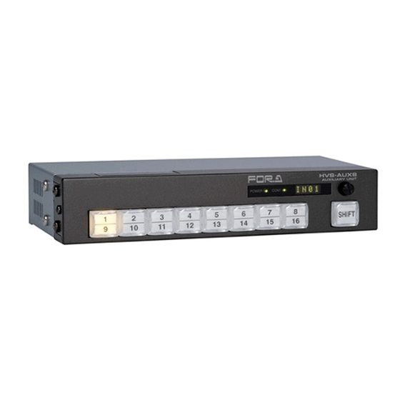
2. Panel Descriptions 2-1. Front Panels 2-1-1. HVS-AUX8 ③ ④ HVS-AUX8 AUXILIARY UNIT POWER CONT SHIFT ① ② ① Signal Select Buttons Used to select signal for switcher AUX outputs as well as HVS-4000 series M/E buses. Note that each button is marked with two signal indications and is used to select one of the two. -
Page 11: Hvs-Aux16
2-1-2. HVS-AUX16 ①a ③ ④ HVS-AUX16 AUX ILIARY UNIT POWER CONT PGM 1 PREV 1 CLEAN 1 SHIFT PGM 2 PREV 2 CLEAN 2 ① ① ① ② ① Signal Select Buttons Used to select signal for switcher AUX outputs as well as HVS-4000 series M/E buses. Note that each button is marked with two signal indications and is used to select one of the two. -
Page 12: Hvs-Aux32
2-1-3. HVS-AUX32 ③ ④ HVS-AUX32 AUX ILIARY UNIT POWER CONT PGM 1 PREV 1 CLEAN 1 SHIFT CLEAN 2 PGM 2 PREV 2 ① ① ① ② ①a ① Signal Select Buttons Used to select signal for switcher AUX outputs as well as HVS-4000 series M/E buses. The output signal can be selected as any one of the signals described below (factory settings). -
Page 13: Rear Panels
2-2. Rear Panels 2-2-1. HVS-AUX8 S/No.00000 DC 12 V ② ⑥ ⑦ CONTROL A CONTROL B SERVICE I/O ALARM ① ③ ④ ⑤ ① CONTROL A Used for cascade control connection between Hanabi series switchers and Auxiliary Units. -
Page 14: Hvs-Aux16/32
2-2-2. HVS-AUX16/32 ② ⑦ POWER AC100-240V~50/60Hz IN CONTROL A CONTR OL B SERVIC E I/O A LARM RATING LABEL ① ③ ④ ⑤ ⑨ ⑥ ⑧ ① CONTROL A Used for cascade control connection between Hanabi series switchers and Auxiliary Units. Note that if cascade control connection is made here, 75Ω... -
Page 15: Internal Settings
HVS-AUX top view BNC2 BNC1 CPU CARD E02435-2 CPU CARD(E02435-2)Default Settings SW1 Setting (service use) HVS-AUX8 HVS-AUX16/32 1, 4: ON(Do not change.) ON (Do not change.) 2, 3: OFF (Do not change.) 2-4: OFF (Do not change.) -
Page 16: Connection
3. Connection 3-1. Arcnet Connection Requirements Connection cable BNC (5C2V or equivalent) Total cable length within one segment Less than 100m Cable length between Arcnet devices (terminals) More than 1 m Available number of Arcnet hub in a system Maximum number of units within one segment 7 units 75Ω... -
Page 17: Connecting To Hanabi Series Switchers
3-2. Connecting to Hanabi Series Switchers The examples of ARCNET connection between the Auxiliary Units and Hanabi series switchers are given in the following. The devices at the both ends of the connection must be terminated by 75 ohms. On the Auxiliary Units 75 ohm termination switch must be set to ON. 3-2-1. -
Page 18: Connection Example (Hvs-300/350/390/Xt100/Xt110/500/600/650/1000Hs)
3-2-2. Connection Example (HVS-300/350/390/XT100/XT110/500/600/650/1000HS) IMPORTANT If the Auxiliary Units are configured in the HVS-300/XT100/XT110/500/600/1000 system, an HVS-ARCNET option is required for connection. Connection Example 1 HVS-1000HS only 15-pin D-sub cable HVS-1000HS (ID 250) Operation Unit HVS-AUX User 75Ωtermination connector (ID 240) 75Ωtermination ON ... -
Page 19: Connection Example (Hvs-5000 Series)
3-2-3. Connection Example (HVS-5000 Series) Connection Example 1 Ethernet cable HVS-5400 (ID 250) Operation Unit HVS-AUX 75Ω terminator (ID 240) 75Ω termination ON Connection Example 2 Ethernet cable HVS-5400 (ID 250) Operation Unit 75Ω termination 75Ω termination 75Ω terminator HVS-AUX HVS-AUX HVS-AUX... -
Page 20: Connecting To Vps-700 Series Switchers
3-3. Connecting to VPS-700 Series Switchers IMPORTANT To control auxiliary outputs for the VPS-700 series switchers (VPS-700, VPS-700RPS, and VPS-715) the Auxiliary Units with firmware version 3.00 or higher are required. First, designate one of the Auxiliary Units as a master and others as slaves. Connect the master unit to the VPS-700 via the supplied control cable as shown in the connection example below. -
Page 21: Arcnet Id And Menu Settings
Connection Example2 VPS-700 VPS-700 OU TO OU TO MU RS-422 1 75Ωtermination 75Ωtermination 75Ωtermination CONTROL A CONTROL A CONTROL A HVS-AUX HVS-AUX HVS-AUX (ID 241) (ID 242) (ID 240) Master Slave Slave <Menu Setting> <Menu Setting> <Menu Setting> GRP? >> 700S GRP? >>... -
Page 22: Remote Mount With Hvs-Aux8Rk
3-4. Remote Mount with HVS-AUX8RK If the front panel and frame of the HVS-AUX8 units are separated using the optional HVS- AUX8RK, connect between the D-sub connector (15-pin D-sub, male) on the rear side of the front panel and the TO PANEL connector (15-pin D-sub, female) with the supplied control cable. -
Page 23: Alarm Connection
3-6. Alarm Connection The pin assignments of the ALARM connector are as shown in the table below. Refer to the table to make alarm connections. Alarm Connector Appearance 9-pin D-sub (female) Pin Assignment Table Pin No Signal Description Communication ALARM OUT * Communication failure alarm, normally open Power ALARM OUT *... -
Page 24: Power On
4. Power ON Power on all devices connected to the system after all system connections are complete. When powering on the Auxiliary Units , the message "INIT", which indicates that the unit is starting up, and then the message "STRT", which indicates that the startup is fully complete, will be displayed. POWER CONT POWER... - Page 25 Warning Messages when connecting to the VPS-700 switcher as a Slave Message Error Action Refer to ERR1 System error Power off and then on HVS-AUX. Check the Arcnet connection with Master unit Arcnet connection A NG (cable connection and 75ohm terminal 3-3-1 failure switch).
-
Page 26: Menu Operation
5. Menu Operation There are several operational settings which need to be made using the front panel LED menu display and the menu control. Explanations on making settings and what settings can be made at the front panel are contained in the following sub sections. 5-1. - Page 27 Setting logic: Setupmenu Setting Range QIK ⇔ AUX16 :Turn to switch between OUT? (HVS-5000: AUX32) (*1) Selects a bus. : Press to select Press and (HVS-4000: M1PG - M3PS) hold * Refer to section 5-2 "Setup LOCK Menu" (the next page) for more OFF⇔CONT⇔SW⇔ALL Enables/disables details about menu.
-
Page 28: Setup Menu
5-2. Setup Menu Item Default Setting Range Description Enables the user to select a bus to be controlled without opening the menu (Bus Quick Select mode). See section 6-4 for details. OUT? AUX1 AUX1-32 (*1) Selects an auxiliary bus to control. M1PG, M1PS Selects a program or preset bus to control. -
Page 29: Free Assign
Note that each button is marked with two signal indications and is used to select one of the two in the HVS-AUX8/16. SHIFT button determines which one of the two signals appearing at any of the above buttons is selected when button is pressed. Upper indications are active when SHIFT is unlit and lower indications are active when SHIFT is lit. - Page 30 Model Button Assigned Bus Available Settings 1-24 IN01-IN24 25-28 STL1-STL4 BLK (BLACK), STK1 IN01 - IN24, STL1 - STL4, 30-31 CLBR STK1 – STK4, MV1-MV2 CLBR, MATT1 - 2, HVS-390HS PGM1 M1PG M1PG, M2PG PGM2 M2PG M1PV, M2PV M1CL, M2CL PREV1 M1PV MV1 - MV2,...
- Page 31 Model Button Assigned Bus Available Settings 1-16 IN01-IN16 17-18 STL1-STL2 19-22 MAT1-MAT4 BLAK, IN01-IN16, 23, 24 COMA, COMB STL1-STL2, 25, 26 COAK, COBK MAT1-MAT4, COMA, COMB 27, 28, 29 PGM1, PRV1, CLN2 COAK, VPS-700 PGM1 PGM1 COBK PGM1, PGM2 PGM1 PRV1, PREV1 PRV1...
-
Page 32: Reinitialize
This returns the unit to factory default settings. After displaying "YES" for about one second, it returns to menu item list. HVS-AUX8: With holding down menu control, press "1/9" HVS-AUX16: With holding down menu control, press "1/17" HVS-AUX32: With holding down menu control, press "17"... -
Page 33: Operations
This section explains how to select output signal in the Auxiliary Unit. Depending on the SHIFT mode, select operations differ as shown in the tables below. Refer to section 5. "Menu Operation" for changing SHIFT mode. If the HVS-AUX8: SHFT mode Selectable Button... -
Page 34: Take Mode
6-3. TAKE Mode TAKE mode will help you to avoid accidental signal selection. About bus assignments, see " section 5-3 "Free Assign". Output signal is switched when SHIFT is pressed after a signal selection. SHIFT should be flashing after a signal selection button is pressed. During flashing press SHIFT. -
Page 35: Setting Quick Select
If the number of the AUX buses exceeds that of the buttons on the AUX unit: For example in the case when HVS-AUX8 has eight buttons and 32 auxiliary buses have to be set on it: Eight buttons on the HVS-AUX8 represent AUX1-8. Pressing SHIFT (lit indication) changes the buttons to AUX9-16. - Page 36 IMPORTANT To display the AUX bus number, do not press and hold down the menu control but press the menu control briefly (less than half a second). The Setup menu will open if pressing and holding down the menu control for a while.
-
Page 37: Specifications & Dimensions
On the frame rear panel: 15-pin D-sub (female) x 1 (inch screws) On the frame rear panel: 15-pin D-sub (male) x 1 (inch screws) Power HVS-AUX8 12 V DC (supplied via accessory AC adapter) 100 V AC to 240 V AC ±10%, 50/ 60 Hz HVS-AUX16/32 Consumption HVS-AUX8 3.6 W at 12 V DC... - Page 38 7-2. Dimensions 7-2-1. HVS-AUX8 (All dimensions in mm.) HVS-AUX8 AUXILIARY UNIT 7-2-2. HVS-AUX8 (Optional HVS-AUX8RK Configured) (All dimensions in mm.) HVS-AUX8 AUXLIARY UNIT HVS-AUX8 AUXLIARY UNIT...
-
Page 39: Hvs-Aux16
7-2-3. HVS-AUX16 (All dimensions in mm.) S/N 9000191 to S/N 9000834 HVS-A UX16 AU X ILIAR Y U N IT PO W ER C ON T PGM 1 PRE V 1 CLEA N 1 SH IFT PGM 2 PRE V 2 CLEA N 2 ... -
Page 40: Hvs-Aux32
7-2-4. HVS-AUX32 (All dimensions in mm.) S/N 9090073 to S/N 9090257 HVS-A UX3 2 AU X ILIAR Y U N IT P GM 1 PRE V 1 CLEA N 1 SH IFT PO W E R P GM 2 C ON T PRE V 2 CLEA N 2... -
Page 41: Hvs-Aux16/32 (Optional Hvs-Auxrk Configured)
7-2-5. HVS-AUX16/32 (Optional HVS-AUXRK Configured) (All dimensions in mm.) O N E A P T L BLANK PANEL FOR.A WHITE GRAY OPTIONAL PARTS HVS-AUX AU XILIA RY UNIT OPTIONAL PARTS FOR.A DARK METALIC HVS-AUX 32 AU XILIARY UN IT A A A A... -
Page 42: Appendix: Hvs-Aux8 Button Labels
Appendix: HVS-AUX8 Button Labels TAKE PREV PREV CLEAN CLEAN PREV BLACK Dimensions 13.4... - Page 43 SHIFT LINE MATT...
-
Page 44: Appendix: Hvs-Aux16/32 Button Labels
Appendix: HVS-AUX16/32 Button Labels HVS-AUX16: S/N 9000191 to S/N 9000834、HVS-AUX32: S/N 9090073 to S/N 9090257 PREV PREV TAKE... - Page 45 CLEAN CLEAN Dimensions PREV BLACK SHIFT LINE MATT...
- Page 47 HVS-AUX16: S/N 9000835 or higher、HVS-AUX32: S/N 9090258 or higher TAKE PREV PREV CLEAN CLEAN SHIFT LINE MATT PREV...
- Page 48 Dimensions 13.4...
- Page 50 Warning This equipment has been tested and found to comply with the limits for a Class A digital device, pursuant to Part 15 of FCC Rules. These limits are designed to provide reasonable protection against harmful interference when the equipment is operated in a commercial environment. This equipment generates, uses, and can radiate radio frequency energy and, if not installed and used in accordance with the instruction manual, may cause harmful interference to radio communications.
- Page 51 2013/08/29 Printed in Japan FOR-A COMPANY LIMITED Head Office 3-8-1 Ebisu, Shibuya-ku, Tokyo 150-0013, Japan Overseas Division Phone: +81(0)3-3446-3936, Fax: +81(0)3-3446-1470 Japan Branch Offices Osaka/Okinawa/Fukuoka/Hiroshima/Nagoya/Sendai/Sapporo R&D/Production Sakura Center/Sapporo Center FOR-A America Corporate Office 11155 Knott Ave., Suite G&H, Cypress, CA 90630, USA Phone: +1-714-894-3311 Fax: +1-714-894-5399 FOR-A America East Coast Office 2 Executive Drive, Suite 670, Fort Lee Executive Park, Fort Lee, NJ 07024, USA...
Need help?
Do you have a question about the HVS-AUX8 and is the answer not in the manual?
Questions and answers